
stayathomedad
-
Posts
59 -
Joined
-
Last visited
Recent Profile Visitors
1,540 profile views


-
Hello all. I have a project to build a venue drawing with beam capacities. What they need is a simple 2D drawing to do overlays on. The issue is that I will be building it in VW and they will then be working with the exported dwg. Does anyone have recommendations for which 2D graphic and content features (symbols, groups, fills, gradients, etc.) translate well from VW to dwg and those that don't? In reality I could build them a drawing with 2D and 3D components, but that pushes even more on my lack of understanding what is lost in the translation.
-

Modeling Additional Slings for Rigging Attachments
stayathomedad replied to stayathomedad's topic in General Discussion
Thanks @VIRTUALENVIRONS! I'm excited to dig into the tutorial! NURBS has always been outside my current skill set. This may be the perfect project for me to start learning. -
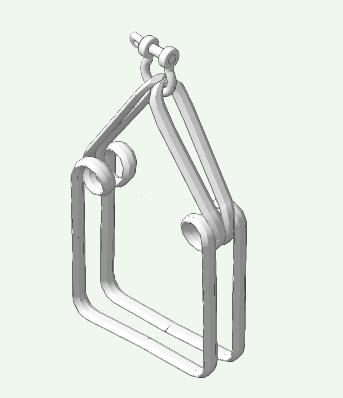
Looking for some initial input into this project. I want to make additional attachment slings for trusses. To not only dial in trim heights more accurately, but also have correct visuals to add to the drawing. For example the 12in imperial sling that is in the VW library is very nicely drawn and is made of a single sling that looks to be 6ft long. I like the look of the span set and I know about "Extrude Along Path" and I suspect that would be a good starting place, but I don't know how to go about getting the areas where the sling is bunched up to look right like it does in theirs. The attachments I want to build will not only include wraps like above but also some chokes, double wraps, etc. I would be happy to take any input into the process. Or...Maybe someone already has built more slings and I can get access to those?

-
Screen tips for Tools and Tool Modes changed for VW2024
stayathomedad replied to stayathomedad's question in Troubleshooting
That solved it! I needed to upgrade to 14.2. Thank you sir! -
Screen tips for Tools and Tool Modes changed for VW2024
stayathomedad posted a question in Troubleshooting
I've noticed that for tools, the screen tips that show up to give you info about the tools appears a little differently in 2024. Previous versions showed the tip if you hovered over any tool. In 2024, the tip only shows up if you hover over the active tool. For the tool modes, I have yet to figure out how to get those screen tips to show up in 2024. Does anyone have any insight? -
Spanner truss not acting how i think it should...
stayathomedad replied to Jayme McColgan's topic in Braceworks
Hey @Jayme McColgan ! You would want to use the Insert Connection Tool with the tool set to Insert Drop. Then select either the hoist you want to use or the Dead Hang hoist symbols in the VW library. Note that some of those Dead Hang symbols have weirdly classed objects and settings and they need a little attention to have correct visibilities. -
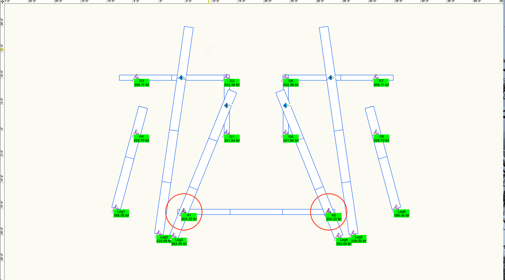
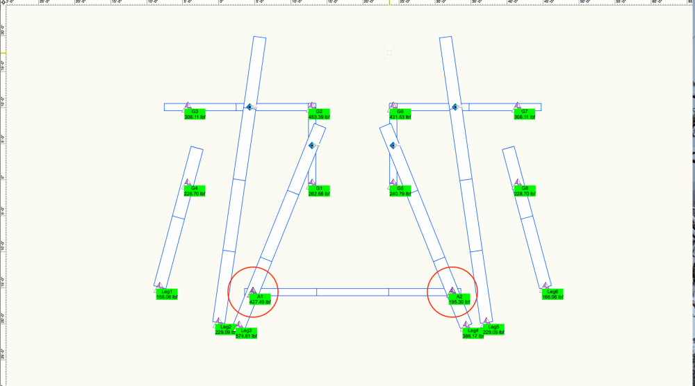
Even after I replace the hoist. I get the [BrxFemHandle not set] error if I run the calculations and have "Compensate drops" turned ON. If I run the calculations with "Compensate drops" turned OFF I get the symmetrical loads of 204.33 lbf that you show in your screenshot. I've always been a bit confused about what compensate drops does to a system and when is it appropriate to use. I am a bit surprised though that it can generate such drastically different load calculations on two points that in reality are going to be close to identical. In reference to the cleaner version of the sample file "CompensateDropsAsymmetry.vwv" posted above - With compensate drops turned on, point A1 comes in at 427 lbf. and A2 at 195 lbf.
-
@Scott C. Parker I had a little time this weekend to investigate the behavior I was seeing. As near as I can tell it is not the customization of the hoist or truss symbols, but rather an issue of having Compensate Drops turned on or off. Honestly, I have always had a weak understanding of exactly what compensating drops is actually doing. With the attached drawing of the simplified truss system I originally referenced, when I have Compensate Drops turned on, the load calcs get very asymmetric, especially at the hoists I have labeled A1 & A2. When the option is off, the loading is symmetrical as expected. Compensate Drops OFF Compensate Drops ON File attached. If you have any insight to help explain this behavior, that would be awesome. CompensateDropsAsymmetry.vwx

-
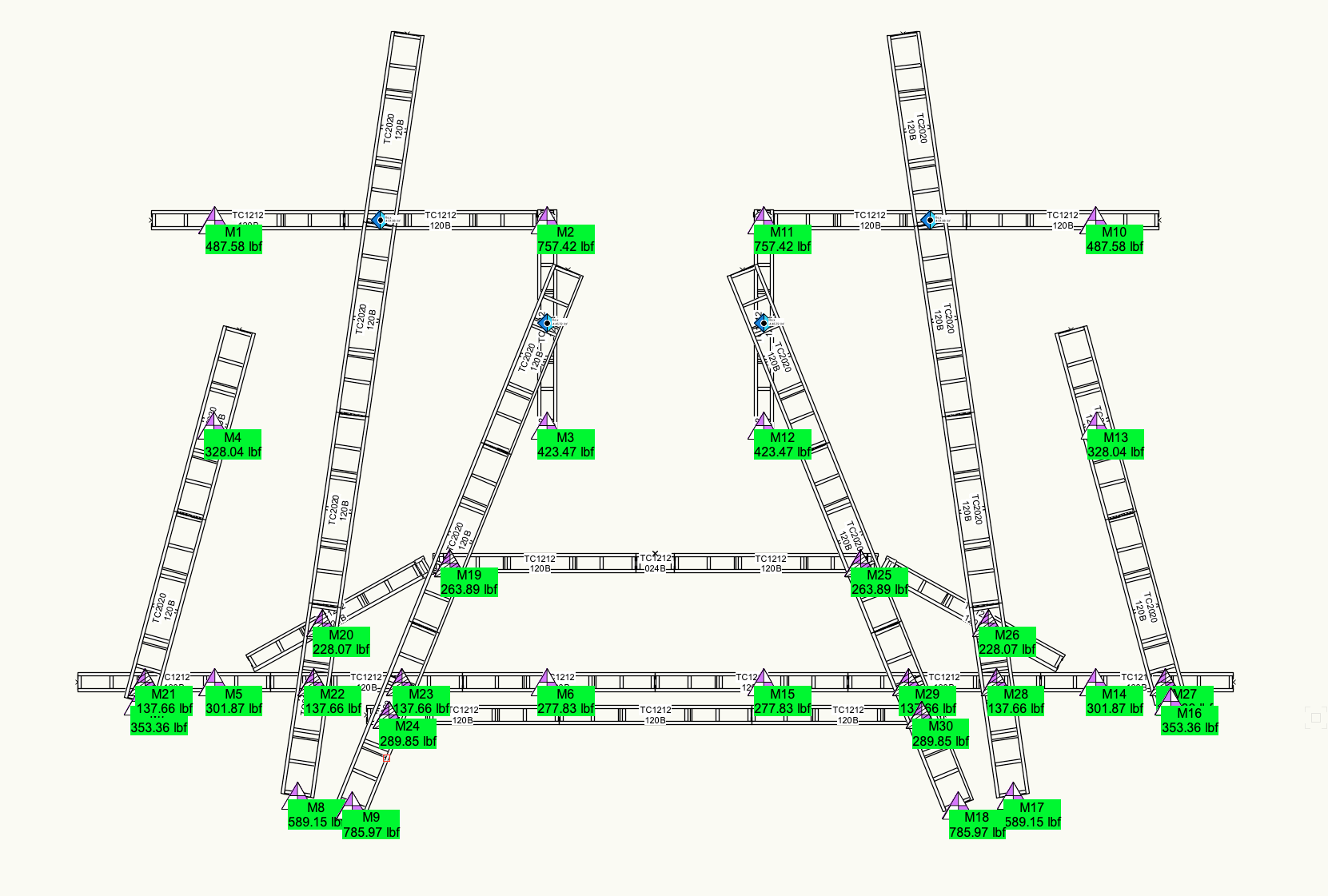
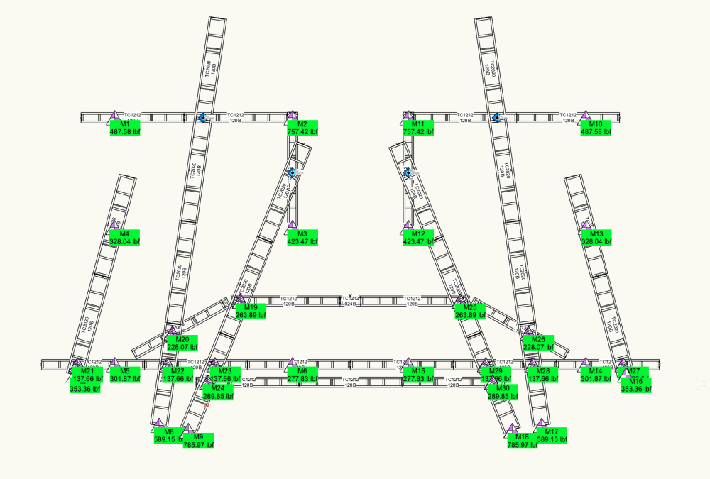
@Scott C. Parker Thanks for the reply and maybe you are still willing to give it a guess. It seems the question is more about my custom truss and hoist symbols than it is about Braceworks and and FEA process. I have customized many of the properties and look of the stock truss and hoist symbols. A total rebuild of my truss and hoist symbols is on my schedule, so understanding better exactly where I screwed up would be very helpful. I rebuilt the truss system using stock symbols and I get the behavior I expect to see. The calculations are symmetrical. But when I use symbols I've customized, I get this. There are many reasons for the various customizations I have made. I have always tried to be as thorough as possible when I make any changes, knowing that I don't want to be screwing with the Braceworks process, but obviously, I missed that mark! I have attached the (2) files. Again, thanks for your time. BW.CustomSymbol.LayeredTrussExample.vwx BW.StockSymbol.LayeredTrussExample.vwx
-
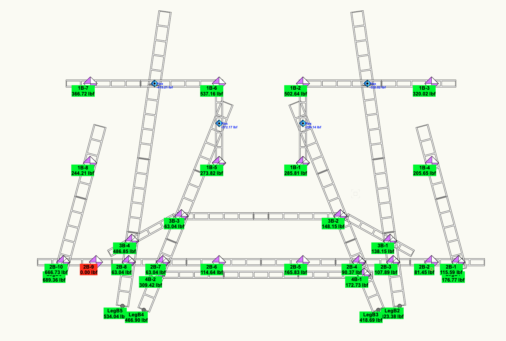
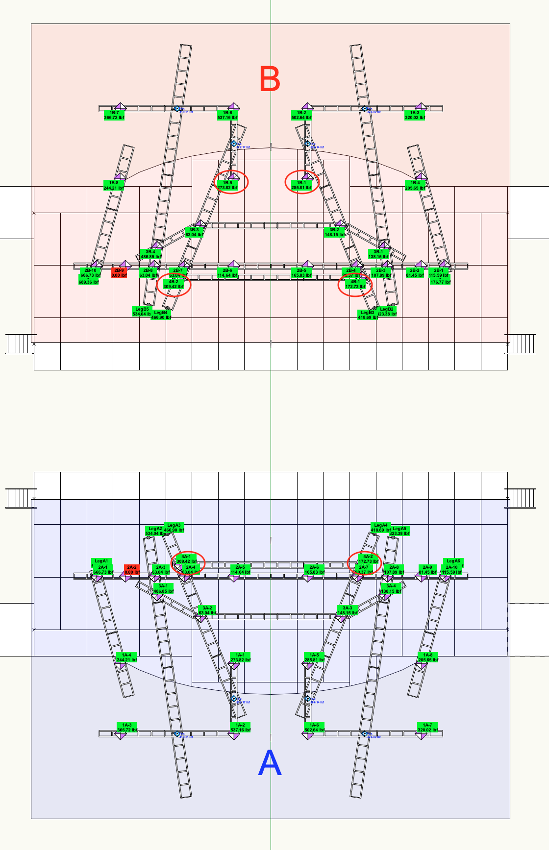
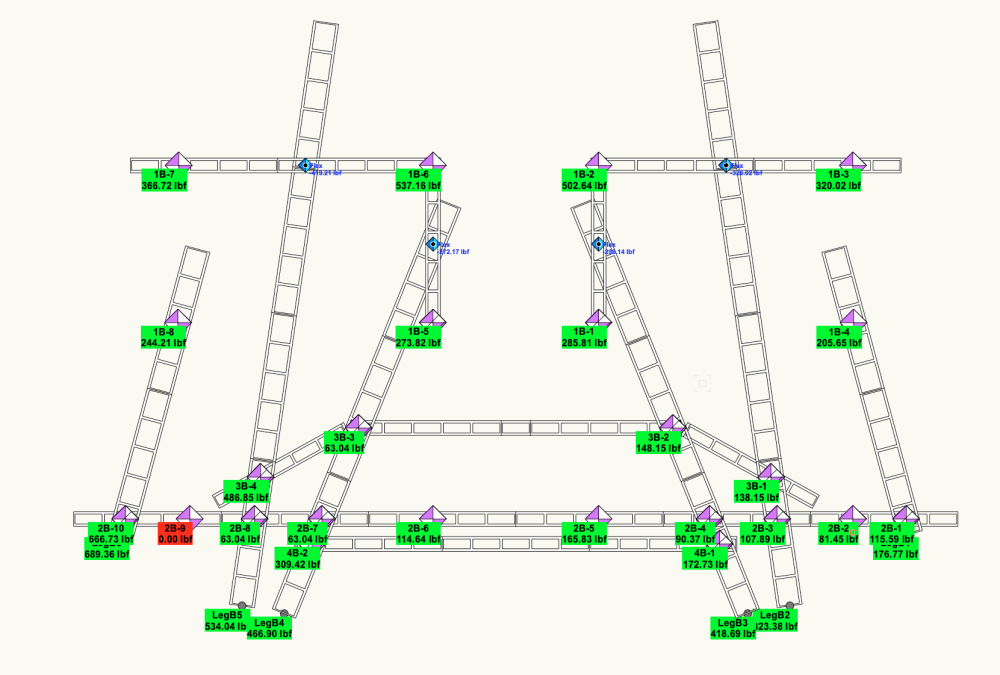
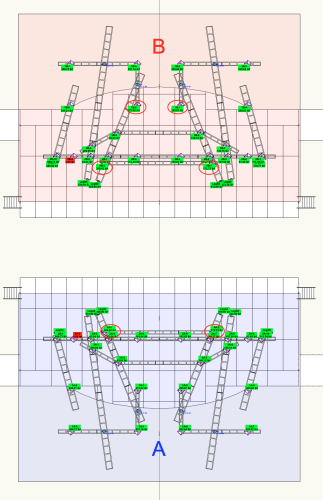
I am working on a multi layered truss structure and I noticed an interesting Braceworks behavior that I would love to understand a bit better. The load calculations shown are on completely empty truss and all truss and symbols are inserted based on a symmetrical centerline. I notice a couple of interesting things. Looking at just the B section - Based on symmetry it seems to me that the loads on either side of the centerline should be equal. 1B-5 should be equal to 1B-1. They are close, but not exactly equal. Looking at 4B-1 and 4B-2, the stage left #2 hoist is almost twice the calculated load of the stage right #1 hoist. I then took the structure and rotated it 180° and created the A section. The load calculations end up being exactly the same, kind of. The loads have switched to the other side of the stage. Comparing 4A-1 & 4A-2, the stage right #1 hoist is now the one that is almost twice the stage left #2 hoist. I got the same results whether or not compensate drops is active or turned off. I am assuming this has something to do with how the FEA engine approaches a drawing and it seems to be affected by the coordinates of the objects. Is there a way to control this? Are there settings to improve the accuracy of the calculations with more complex layered truss systems? When the differences are rather large - how do we know which one is most accurate?
-
Re-create the truss but add the truss weight into the settings BEFORE the truss is created.
-
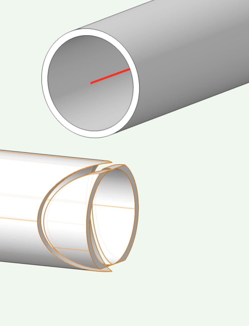
I have hit this wall before and thought I'd check and see what I can find out here. I have two pieces of pipe modeled and want to joist them at right angles. When I do this and use the Subtract solids command I get the little left over pieces on the section pipe inside the other pipe. I end up creating an additional extrude and use a solid extrude as the sectioning object to get the piece inside of the pipe to be deleted. But I'm wondering if there is a cleaner way to solve this that doesn't require me to make an extra extrude for sectioning? Thanks. Harry
-
Woohoo! I hadn't noticed the new setting. Thanks @SketchyJed33
-
This is not the first time I have run into the issue of the Split tool not behaving as I expect. I don't do a whole lot of 3D modeling, so I usually stumble through it and never completely understand the why. Today I am messing around with a truss symbol and I want to adjust the overall size. My project involves taking the Generic Solid and cutting out certain sections to resize it. Using the Split Tool to do this, it works some times but doesn't work other times. Looking at the attached file, in a top view, I can use the Split Tool and cut the Solid into two solids if I draw a horizontal line through the oject. But if I draw a vertical line, the object highlights red, but doesn't actually split into two objects. Messing around a bit more I can see the tool seems to work if it splits the tube portion of the solid but not when just splitting some of the other parts. Can someone help clarify this behavior for me so that I can better understand. It just isn't intuitive to me for some reason. Thanks. Split Generic Solid.vwx
-
Is there a VS to delete sheet layers? I am very new to VS and I have a project where I would like to delete sheet layers. I can see when I create a Braceworks report that there are sheet layers being created and deleted. I would like to create a VS that does a similar process. Thanks for your time.