jcogdell
-
Posts
960 -
Joined
-
Last visited
Content Type
Profiles
Forums
Events
Articles
Marionette
Store
Everything posted by jcogdell
-
yes, select the fixture and open the software console in the window menu.
- 1 reply
-
- 1
-

-
If you have not already done so please contact tech support, below is the link to the online help request form from our website https://www.vectorworks.net/support/help
-
Hi Jazz Do have any of the manufacturer details? I can put a content request in for it if you do. Gruße Jesse
-
How big is your design? Does it have a lot of symbols? or is it more geometry based? Could you post the file or PM it to me? so that the Dev team can have a look at it Gruße Jesse
-
Hi Dave This is the result of the interaction of the ganging tool's preferences with the label legend assigned to the lights. As you selected the option, in the ganging tool preferences, to gang 'by circuit'' you will get a 2 part label for the ganging object (this will also happen if you select the option gang 'by channel and dimmer'). This is because in both of these cases the ganging tool label label is referencing the data in 2 data fields and combining it, 'by circuit' references both the 'circuit name' (top) and 'circuit number' fields from the fixtures. The horizontal offset that you can see in your example appears if you have set the one of these fields to 'right reading' in the label legend assigned to the fixtures. The easiest way round this is to prepare a label legend for the fixtures that you plan to use the ganging tool with , that does not have any right reading data fields in it.
-
Cheers Mark That's an approach I hadn't considered.
-
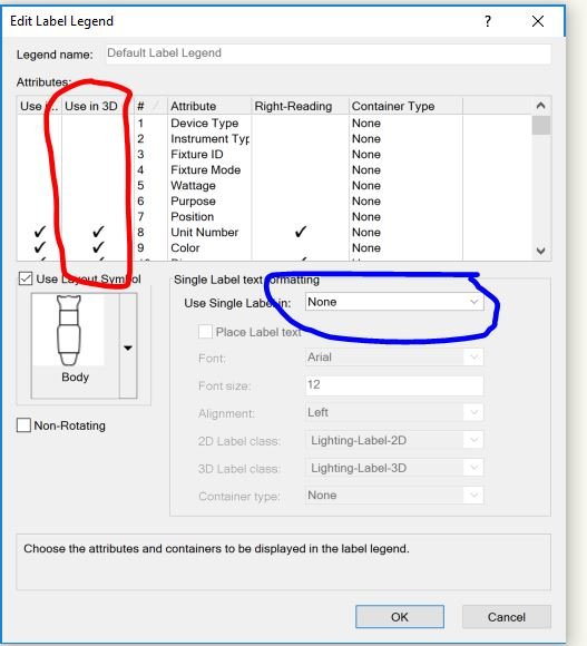
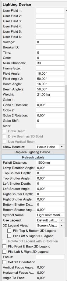
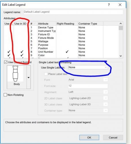
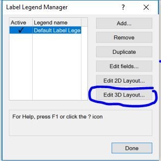
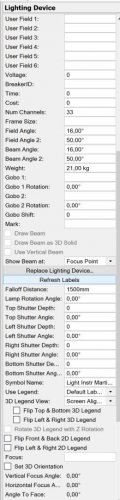
First, in the edit label legend menu make sure that you tick the fields that you want active in your 3D label in the use 3D column (red) if you want to set the 3D layout for the fields in relation to the fixture use the drop down menu highlighted in blue, choose none and then use the edit 3D layout option in the label legend manager to set up the layout. Otherwise the legend will use a default layout, depending on which option you choose. After assigning your legend to the fixture make sure that in the object info pane you have selected a 3D Legend view, otherwise it will not be visible (I normally use screen aligned). Lastly you may need to use the 'refresh labels' command in the OIP if you change views.
-
@mharvey Although it is not directly in our library yet you can download it directly from the Elation website, I've linked below for you https://www.elationlighting.com/tvl-cyc-rgbw
-
Just a quick clarification As Nina ha said we are working on the DWG/DXF issue and will continue to do so. However we are hoping that other CAD developers will adopt the MVR and GDTF standards. We have had several DWG based CAD Developers express an interest and have started conversations with them. We hope that our competitors involved with developing event planning applications will get involved, as it will benefit our industry as a whole and specifically you our users.
-
Vectorworks as a founding memeber of the GDTF Group, is currently working on establishing a new set of file and data transfer standards and protocols for the entertainment industry. Similar to how IFC and BIM have been established for the Architectural and Engineering industries. GDTF is a universal file type and protocol for the control of lighting fixtures and any other dmx controllable device that will function for any participating Lighting console, Previs application or CAD package. Effectively it is hoped that this will replace the need for each individual console type, CAD package or PreVis application to use a separate unique personality file or symbol. MVR is designed as a universal standard and file type for 2 way communications between CAD software, Lighting consoles and PreVis packages. It will establish a base standard/protocol for how each participating application stores and references data. This in turn will mean that any participating application will be able to correctly import from and export to any other participating application. An example of the potential of this is exporting an MVR from Spotlight that will automatically patch your lighting console and include all relevant fixture personality files needed by the console (in the form of GDTF's). You can then make a change to the patch in the console and export an MVR back to Spotlight with the changes to keep everything up to date. This can be repeated as many times as needed to finish your design! For more info about both GDTF and MVR, check out the GDTF share website https://gdtf-share.com/ On the website you can find a list of companies that are involved. If you use software from a company not yet involved, I recommend getting in contact with the developers and making the case that you would like to see them take part. The more users such as yourselves that get involved and use the new standards the quicker we can establish GDTF and MVR as the standards for our industry.
-
Just to clarify there are 3 versions of Vision currently available Professional Vision which is limited to only 1 DMX universe, Professional Vision Plus which has 4 DMX universes and Professional Vision Unlimited with unlimited DMX universes If your license is for the plus or unlimited version please contact US tech support and have them check that you have been assigned the correct license type, as the behavior that you are reporting indicates that your copy of Vision is limited to a single license
-
What Version of Vision do you have, depending on which version you bought you may only have 1 controllable DMX universe (student or basic). This would explain the patch behavior you are experiencing. As for color ( i asume you are talking about gels) you will need to manually set these inside of Vision. Spotlight and Vision currently use different formats for the symbols. The color field in the Spotlight lighting instrument is only for documentation and does not transfer to Vision. To assign a color to a generic/conventional fixture First select it in the scene graph (you can multi select fixtures) then in the properties window open the color wheels tab, select color wheel 1 and click on assign this will open a dialogue box allowing you to either pick a specific gel to assign to the fixture or manually select a color to assign.
-
@pgorski1984 As jugfire has pointed out this is partly due to your safety factor settings in the Braceworks Preferences, there are 2 other things that are affecting the calculation, the first is the cable flat-fare in the Braceworks preferences (default 2kg per meter) and the second is the positioning of your 2 hoists, unless they are exactly symmetrically placed on the truss each will have a slightly different load as one hoist will be carrying slightly more of the truss weight than the other. If both hoists are perfectly placed then the basic calculation including the safety factor and cable flat-fare would be as follows truss 62.4kg cable 18kg safety factor 1.35 (62.4+18)/2=40.2kg 40.2 x 1.35= 54.27kg per hoist If you need further help with Braceworks contact Design Express in Poland and ask for Robert Janiak their Spotlight and Braceworks specialist. He will be more than happy to help you.
-
Inlination oef a truss system for calculation
jcogdell replied to FinchProduction's topic in Braceworks
The way to do this is to select your truss (all connected sections that you wish to do this with) and toggle the draw 3D only option on in the Object Info Pane next group select the trusses and lights, change to the appropriate 3D view (front for example) select the rotate tool from the basic tool palette and use it to rotate the selected trusses and lights to the angle you want. Changing the angle of the trusses and attached lights will break the connections for rigging hoists/deadhangs/bridles so you will then need to re-attach them before you can run any Braceworks calculations. -
The lighting pipe tool has not been removed. If it is missing from your rigging tool-set you can add it back in by going to Tools-Workspaces-edit current workspace once inside the workspace editor open the tools tab expand the spotlight tools on the right, scroll down till the lighting pipe tool is visible and then drag and drop it into the tool palette of your choice on the left (typically lighting or rigging) This will add it to the tool-set of your choice
-
Also you can save your numbering settings as a template to reuse in other documents and it can be used on any object in Spotlight that has a data record, such as trusses, hoists etc.
-
Hi Robert The Tomcat truss is grey because Tomcat has not provided us with the background data necessary for Braceworks. When ever we have a truss type that is missing the data for Braceworks calculations (including trusses created with the old straight truss tool), a default set of data is applied and the heat map function will not work with that element to highlight this.
-
Spotlight Truss and Motors Legend Tool
jcogdell replied to allannathan's question in Wishlist - Feature and Content Requests
Hi Allan These features are in Spotlight 2019. You can find the hoist legend function in Spotlight-reports-crate hoist symbol key will put a hoist legend on your plan Hoist reports are created in the same place and can placed on your plan the same as any other report or worksheet. Go to Spotlight-Rigging-Replace truss and use the export function and it will create a truss report with what is needed for each truss system. In the same interface you can access the truss inventory where you can export your truss inventory totals (use vs in stock) as a .csv file You can also use the worksheets to prepare truss lists, there was a recent forum thread related to this, I've linked it below for you to look at. -
Hi Alan If you need actual lessons I would suggest getting into contact with Peter Neufield at OzCAD. He is very experienced and can provide both support and training. gruße Jesse
-
When you run your on pc console and Vision on the same computer they should connect automatically, as long as both are configured for the same control protocol (Artnet, SACN, MA NET), also MA Net 2 will work without a security dongle in this scenario as well ( dongle is only required for physical consoles, as far as I remember). Regarding the 2nd monitor if you are using one computer for both Vision and your on PC, it makes life a lot easier.
-
Hi Suni Another tip is to use a second monitor if you can, so Vision is on one and your on pc console software is on the other, makes it much easier. Regarding Artnet or any of the other protocols the make sure that both vision and the console software are set to use the same protocol, it should then connect automatically. hope this helps Jesse
-
Just to clarify you set the basic position of the 3d label legend elements when that legend is first created. This is done in the label legend manager in a similar way to the old 2D label legend workflow ie pick what you want to display (for 2D and/or 3D) and then position the labels round your fixture in 2D and in 3D. The drag and drop is for when you have the legend obscured by another fixture or object. Unless your plan is very crowded (fixture counts in the 1000s +) you should only have to edit a few in any given model as long as the label legend was properly prepared.
-
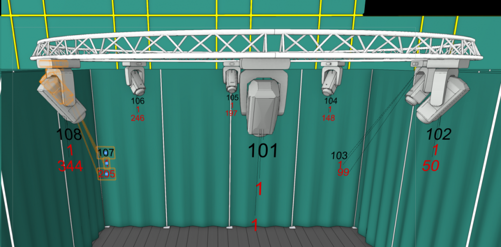
@Gabriel Chan Spotlight label legends received an overhaul in 2019. The 3D label legends can now be orientated in any direction and re positioned by selecting and dragging to where ever you would like them in relation to the fixture. A leader line has been included to show which fixture the legend is associated with. see below
-
Is it just that you are receiving the warning about the symbol containing 3D info only? if so just go ahead with the conversion, the only thing that will not be displayed is the simplified view of the truss objects, the hanging position will function as normal. If that is not the issue please upload a copy of your save file and I will take a look, as currently it seems to be working fine for me (2019 sp2). gruße Jesse
-
Hi Hayden You are doing nothing wrong! Scott is correct that the blue symbol is part of Braceworks. It is called a Truss Cross connection and represents where 2 structural objects, such as trusses or pipes, are connected to allow the transmission of forces for Braceworks calculations, you can define the connection as solid or flexible. 2 real world examples of this would be using scaff clamps/cheeseboroughs to attach an out-rig pipe to a truss (rigid connection) or hanging a perpendicular 3 chord truss directly under a 4 chord truss using a steelflex (flexible connection). There is a problem that your example picture highlights.The problem is that spigoted corner blocks should not be able to connect together flush without space for the female side of the connection or an adapter. The truss cross connection is the correct behavior for the vertical connection but it should not be possible create the horizontal connection between the 2 corner blocks shown in the picture. I will open a bug report, thanks for bringing this to my attention gruße Jesse