acdeslx
-
Posts
116 -
Joined
-
Last visited
-
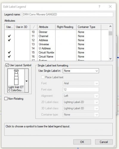
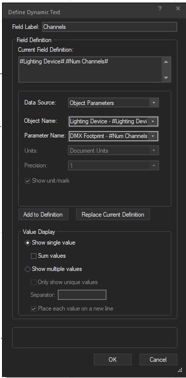
Tried that but now it shows no values in that field. Is it possible that it can't pull the data because it's being auto-entered into the footprint field from me choosing a fixture mode in the OIP? The pic belows shows the text box definition in the graphic legend.
-
I'm now using graphic legend as my "legend" for my lighting plots. I'm trying to add a field for the number of DMX channels that the fixture uses. I would think it should be fairly simple using the data already present in the "Lighting Device" object as "DMX footprint". The method I'm using is to add a text field to the cell layout and use the field definition "#Light Info Record#.#Num Channels#" with the data source being the record format. This method works for naming the fixture so I thought it should work for any other data that I can see in the OIP. I am getting a value but it's not the DMX footprint that's shown for that light -- it seems to be the profile using the max. number of channels as shown in the "fixture mode" dropdown in the OIP. Not sure what I'm doing wrong. Any help would be appreciated. Cheers.
-
Can I replace a 2d/3d symbol with a lighting device?
acdeslx replied to acdeslx's topic in Entertainment
Thanks for the ideas. @Scott C. Parker I'll have to see how that translates into Vision but it looks like I'd have to do that individually or can I convert the base device in the Resource Manager and update across the drawing? @Kevin Allen What I'm replacing it with is an actual lighting device (Generic 2m Emissive RGB Sphere). I basically need to create a glowing ball that I can program in Vision which I know how to do on it's own but I'm trying to avoid manually replacing all the ones in the current drawing. -
I have a set design that has hundreds of spheres in it as "2D/3D symbols". I want to replace these with an emissive sphere lighting device. I can choose the sphere, select replace, choose the emissive object and it changes the shape in the drawing but in the OIP it remains as a 2D/3D Symbol but with the name changed to the emissive lighting device. I'm not able to add any lighting-specific data to it. Is there a way to do this or do I need to replace them one at a time? Thanks.
-
Thanks... 420 emissives to go... <sigh>
-
Thanks Jesse. This is exactly what I'm looking for. Is there a way to do automate all of this instead of assigning each emissive "block" the DMX info in one action instead of one at a time? Cheers. Dave
-
I'm really hoping this hasn't been addressed elsewhere in the forum but I couldn't find it if it was. I'm trying to do some pre-viz on a set with 100+ translucent cubes -- essentially an ultra-low res video wall. In my actual rig, I have an RGB fixture mounted directly behind the block and when I turn it on, the whole cube glows. I'm trying to set that up in VWX so that I can drop it into Vision but none of my methods seem to work. I'm using a Chroma-Q Colorforce-12 (RGBW, 4-ch mode) behind an extraction that I created with a frosted glass texture. I try to port this into Vision and it really gives me nothing useful. The light shows up on the surface that it's pointing towards but really doesn't go through and make the cube glow. I'm not sure if this is an issue with the texture I'm using or should I be using a material or is this completely the wrong direction to be looking? Any help would be appreciated. Thanks.
-
Dimension tape hashmarks don't appear in Sheet Layer
acdeslx replied to acdeslx's topic in Entertainment
Figured it out... For those that run into this, the pen colour wasn't set correctly. Text showed fine but the the lines wouldn't. -
Found this one today... I'm putting in some Dimension tapes to help out my crew with a drawing. When I create it, all is good but the hash marks disappear as soon as I stop editing the object. If I roll over it or edit it, they're seen. Currently I'm using them in the annotation layer in a viewport on a sheet layer. I have the viewport detail set to hi, and the sheet DPI is 200. I tried creating the tape in a drawing layer and then just adding that layer to the viewport but the same problem happens. Any ideas? Thanks. Dave
-
I tried parasolid in various forms and VW wouldn't even open them. It just hung after I chose to import and selected to either import or symbol or as not. The only real luck I've had is exporting the file as a DWG. It will import into VW as a 3D object which I can do a flyover with no problem. Strangely, I can't do a walkthrough which seems odd because the 3d is there.
-
I'm in need of some opinions. I am -- and will continue to be -- receiving some massive (300+ MB) files created in Rhino that I need to make use of in VW 2022. If I import them as .3dm files then it can take up to 30 mins to import and then any editing is painfully slow. If I import them as .dwg files then the file sizes are more manageable but when I try to visualize the file in 3d, I can use the Flyover Tool but none of the others will display anything (Walkthrough, Translate, etc.). Slow editing is also a problem but not as bad as the .3dm. If I need to buy a new PC then I will but I'm not really sure if the lag is from the processor speed or GPU speed or both. I'm current running: Intel Core i7-7700HQ (4-core) 32 GB RAM Nvidia GTX 1070ti w/8GB dedicated memory multiple SSDs for storage Any thoughts would be appreciated.
-
I'm using a drawing that I drew in VW2019 and am now working on in 2020. Everything seems to be find but whenever I modify the Summary List with all my fixtures, VW hangs and won't recover unless I force it to quit. Here's what I've done: - replaced all the fixtures in the drawings with ones in the VW2020 library - deleted the Summary and built a new one from scratch - Purged all the extraneous data in the drawing - saved, closed and opened the drawing at various points of change and deletion to see if it made a difference I seem to be able to make it happen whenever I try to re-order the component list in the tool. I'm trying to avoid re-drawing the whole file if at all possible. Any ideas?
-
Hi Justin. I'm still running 2019. Perhaps I'll move this particular drawing to 2020 and give the new version a test. Thanks for the help.
-
I'm using a number of Christie Lites' 7.5 degree T-link bars in a truss system. I can't seem to make the truss all one system while accurately angling the truss to the angle forced by the T-link bar. For example: Step 1: Place a 6' piece of truss, connect another 6' piece of truss to it, connect a 7.5d bar to those -- all good Step 2: Connect a 6' piece of truss to the bar - still good However, the connection is still a straight connection and doesn't take the 7.5 degree push into account If I rotate the piece of truss to match the angle then it is no longer part of the "system." Is there a way to place the truss at the angle forced by the T-link bar or select the truss objects and force them to become a "system." I'm trying to use Braceworks to calculate my loads and well... without it being a "system", I don't know how to make it work. Thanks. Dave
-
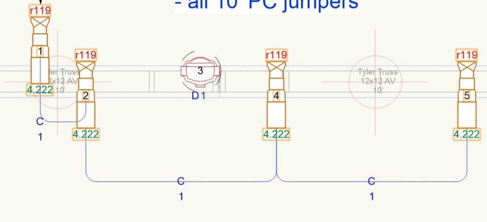
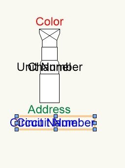
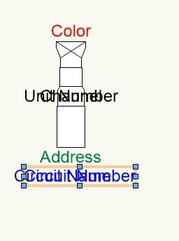
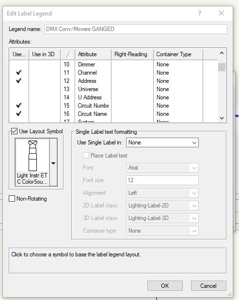
I tried what you mentioned and it still didn't work. Attached are my settings and what they do... any ideas would help 😉 Pic #1 illustrates what I'm seeing when I've applied to legend to the fixtures and then ganged them. Pic #2 shows the 2d layout of the legend. Circuit name and number are on top of each at the bottom in blue but offset horizontally. The text is all aligned as CENTRE. Pic #3 shows the fields -- none are "right reading"