


jcogdell
-
Posts
960 -
Joined
-
Last visited
Content Type
Profiles
Forums
Events
Articles
Marionette
Store
Everything posted by jcogdell
-
I just had a quick look on the ETC Augment 3D forum and found the following info from ETC "Howdy! As mentioned above, with VW2023, we are not developing a plug-in, but instead are using MVR export. For this, you will need VW2023 SP2, and Eos v3.2. Eos v3.2 is going into open beta next week, so keep an eye on these forums to sign up and download the software." You will need to reach out to ETC directly to get more info
-
You can use a Data tag to display the position that the summary is set up to display, choose the active filter parameter of the Instrument summary object when you set up the tag. This can also be used as another route to change the filter setting as well! As far as I can tell the position height and fixture weight options are broken, I'll get a bug report opened
-
This is a bug, I'll open a bug report for it.
-
I just tried to reproduce this and as far as I can tell it is working correctly, I used 2023 sp2 on a win 10 laptop can you post a sample file?
-
Create blank Bridle Configuration screen
jcogdell replied to Martijn Wingelaar's topic in Entertainment
Hi Martijn at this point I can't find a way to do this, so I've put an enhancement request in -
Hoist Tool - Dimension Arrows Don't Rotate?
jcogdell replied to Dan Hoffman's topic in Entertainment
Hi Dan I'm not sure if its an oversight (bug) or works as designed with the new hoist but I agree it makes it much easier to understand by having the visual cue of the rotated dimension arrows Either way I'll open a JIRA for it and try to get it addressed- 1 reply
-
- 1
-

-
Thanks I'll get it fixed
-
I'll put in a request to have the help updated,
-
There is now a modifier key to control whether the cable can leave the path before the end of the path. on windows the modifier key is alt
-
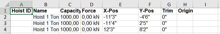
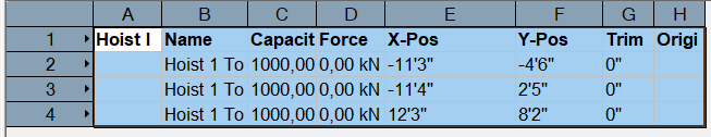
I just tested this using 2023, using the Hoist report command and the worksheet export excel function, and as long as you change your document units to feet and inches with no fractions or decimal places before creating the report it will display correctly in Excel top image is the Spotlight hoist report and bottom is the Excel sheet that was exported using the worksheets export to excel command
-
@Ben59 The replace truss type will only work when both truss type libraries have the same lengths available, from looking at the ST500 library it doesn't include any trusses of the same standard lengths as the sc390 library. Normally in this scenario you would select the truss line and use the change configuration button in the truss object properties to change the truss lengths in the line before running the change truss type command, this way the lengths in the line will match what is available in the new truss types library.
-
The most likely cause is the custom furniture symbols, if they have a lot of heavy geometry (meshes, NURBS etc..) it can have a big performance impact on seating section, due to the number of symbol instances that the section can contain. The size of the seating sections can also have a big impact on performance. In the case of the custom furniture make sure that the 3D geometry component is made up of generic solids and look at the level of detail of the symbol
-
I've opened a bug report for this as it shouldn't be happening
-
Hi @åge-marius This Data tag is not correctly set up, Roof force should be the total force acting on the rigging point including the hoists own weight and should be in kN In 2023 it should be using the parameter 'High Hook force - #ReactionForce#', Workload should be the total weight acting on the hoist not including its own weight in Kg in this case it is the total weight acting on the rigging point It should be using the parameter 'Hook weight Equivalent - #ReactionForceWeight_formated#' I'll get a bug report in to have it fixed,
-
A loom can include any type of cable. The feeder, jumper multi and data cable type classifications are from the original Spotlight cable tools, and were carried over into the new tools to avoid changing terminology that was already standard in Spotlight. There isn't a fixed use for the tape color code field in the cable object, though its more commonly used for loom or truss color codes, rather than a company specific cable length or id marking. I'll add this as a enhancement request
-
Duplicate truss crosses in the same plane / space
jcogdell replied to Mark Aceto's topic in Braceworks
@Mark AcetoI've had a look at your file and as far as I can tell the issue is being caused by the lower layers of unistrut being too close together, I found moving them each about an inch apart stops the duplicate truss crosses being created. I've Dm'd you a fixed version of the file -
Here's the direct contact for the UK Tech support team 01635 580318 uktech@vectorworks.net
-
What import settings did you use in the Import DWG dialogue? There are a number of settings in the advanced section that may help, including the new option to only import the DWG layers you want. You can also control how the DWG blocks import and control how the DWG layers are imported (converted to classes, which Spotlight layer the DWG classes will be imported into and give them a prefix so you can easily identify them and control their visibility. Another thing to check is how many resources your active file has after importing the DWG, depending on how well the DWG was prepared for use in other software the import process can create thousands of resources, in some case a symbol for each line in the DWG. This can have a huge performance impact. Are you drawing directly on top (same layer) of the DWG in Spotlight? Best practice is to make sure all the DWG content is on its own layer, so you maintain better control of the your file. Another possibility that may help is asking the Wysiwyg users to use a different file format, wyg now supports (parially) the new MVR format which can be used to get the design into Spotlight. your will likely still have to convert things like trusses and lights into their Spotlight versions, but it may give you better results. Though in my experience this normally works better when the design starts in Spotlight rather than in Wyg. Have you contacted your local distributor, Dekantus for help? Scott Campbell will be able to help you with the DWG import process as well
-
Hi Wesley I've had a look at your file and it looks like there are 2 issues that combined are causing the problem. The first is a known bug where if the bumper has a hanging angle hoists will not correctly attach to it. The second is also bumper related, I'm not sure if this is a works as designed or a new bug but using any option other than 'Symbol' 'Default Bumper' icauses Braceworks to give the error message that the speakers are not properly supported. To fix your arrays, change the bumper to to use the symbol option and choose the default bumper symbol, then change the bumper angle to 0° hit the update button in the array properties and reattach the hoists. You should then be able to calculate the arrays
-
It may be a error stored in the file VGM graphics cache, a possible solution is to turn the graphics caching off save and restart Vectorworks. The Save VGM graphics cache is in the File menu> Document settings>Document preferences If this fixes the issue you can turn the caching back on afterwords, as it create a new cache which shouldn't have the old error in it aymore
-
Hi Wesley I just tried to reproduce this and couldn't (2023 sp1 using a win 10 PC). If you are still having this problem could you DM me the file?
-
The export gLTF/glb command was added with 2022 sp3 as part of the updated MVR and GDTF support.
-
Not yet, its on the list of issues that need to be addressed. I find the easiest way to select cables when there are a large number of them following the same truss or path is to select the cable object labels, which then selects the cable as well. Try giving the path a very heavy line weight (1.0 or more), this makes it much easier to see the connection highlight and its also easier to select the path. Another option that may help is to change the paths fill colour (make it very pale or with a partial opacity) so that the connection highlight is more obvious. This is a bug, I thought this had already been squashed as it has cropped up a couple of times in the past. I'll reopen the bug report Are you in a 2D or 3D view when trying to enter the path, one thing I've noticed myself is that with a complex path it is much easier to control where the cable enters and exits a path in a 3D view than in a 2D view. Another option is to add an extra vertex into the cable route near where you want the cable to enter the path, by clicking on a nearby piece of geometry, for example on a truss beside where you wish the cable to enter the path.
-
In 2023 we added a modifier key (hold alt on PC or command on mac (I think, I'm not a mac user)) to the cable tool to control whether the cables will enter or exit a cable path at any point. We found that cables were often jumping out of the paths at odd locations (such as cutting corners at the end of a path) and decided that having more user control over the behavior was needed.
-
@DeadInside Have you customized the lighting device parameter names (in File menu-Document settings-Spotlight preferences-lighting device parameters) or are you using the default parameter names from the German localized version of Spotlight? If you changed the parameter names check that you are using the correct worksheet name for the parameter, as this can't be changed. If you are using the default German parameter names and haven't changed anything please contact tech support at Computerworks, the German distributor, they will be able to help figure out what is wrong