AceRoehrborn
-
Posts
47 -
Joined
-
Last visited
-
I have socco breakout in my drawing. I would like to add a data tag to the cable style to indicate which circuit of the socco breakout goes to each light. I understand how the data tag works, I just need to know what data tag field I am looking for? Also When moving around a socca breakout on the drawing (distributer) is there a way to prevent the auto re-calculation of cable length?
-
Hanging Position Hoist connection to Beam
AceRoehrborn replied to AceRoehrborn's topic in Entertainment
Thanks Jesse! -
It would be really great if there was a way to associate dimensions to 3d Objects and symbols. I frequently draw stages, or lighting trusses or other items using Vectorworks tools and or our own symbol library. I need to show the location of the stage or lighting trusses in the room. For example how far the stage locates from the back wall of a venue for instance. On a sheet layer I pull a dimension from a wall or other identifying location to a corner of the stage. The stage is drawn with a symbol. The dimension will snap but not attach with the green square. Later on, when the location of the stage moves by a foot or two I have to come back to each sheet layer and update all the dimensions. It would be very useful if there was a way to attach the dimension to a symbol or a lighting truss object or fixture or any 3d/hybrid symbol for tha matter so that when changes inevitably happen it is not necessary to go re-dimension everything. I know there are some solutions with data tags but often good old fashion dimension lines are a more clear way to communicate. Thank you.
-
I am having some trouble connecting a truss (Converted to a hanging position) to a beam with a hoist. If I draw a truss 40' long (4 sections of 10' 12x12 truss Or any other truss) and convert it to a hanging position I can't seem to get a hoist to connect to both the truss and the beam. I can attach to the truss OR the beam but not both. The truss is placed below a rig beam, no bridles or anything fancy here, just beam to hoist to truss. I think I am using the hoist/beam tools correctly. If I place a single section of truss under the beam. If I grab the hoist tool and hover inside the truss near the beam it will attach the hoist to both the beam and truss as I expect. If I snap additional sections of truss on, it still works. It seems to break only when I convert the truss to a hanging position. Is this a bug?
-
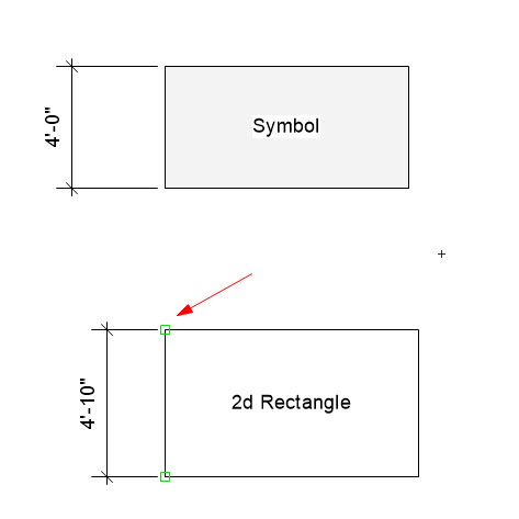
Short question: How do I associate dimensions to symbols so when the symbol moves the dimension automatically updates as well? Detail: Most of the drawing I do is for entertainment and the workflow relies heavily on symbols. It is common to draw a stage out of symbols, then lighting trusses using symbols and plugins etc... From there I create viewports to sheet layers and dimension in the annotations of the viewport. Pretty common workflow I think. On a complex drawing there could be quite a few dimensions and that is all fine, until the venue needs 5' more feet of backstage space and everything has to move. I don't really want to have to update all the dimensions on the various sheet layers manually. When drawing in 2D like the second image below associations are create and indicated by the green squares. This dimension will auto update if that object is moved or changes size. However the top image is a symbol and there seems to be no way to get the dimension to associate to the symbol. This can't be an actual limitation, I have to be missing something right? This symbol is a hybrid symbol so it would think it should be reasonable to associate to the 2d portion. If this is not possible does anyone have any cleaver workarounds or do we all just spend hours updating dimensions regularly?
-
Where do I select the standard sheet size? Where is the format for any printer option?
-
What controls the page size settings of a newly created sheet layer? I mostly print to 11x17. It would be nice if when a sheet layer was created it was automatically that size. From File - Page setup I have selected a printer and defined the page size as 1 page horizontal and vertical with a paper size of 11x17. I have all existing sheet layers in a drawing set to the printer I want and 11x17 page size. When I create a new sheet the printer setup is correct with paper size, but the pages are Horizontal .64 and vertical 7.65 paper size is essentially set as if it were 8.5x11. Also related, is there a way to default to 11x17 even when that printer is offline or not available on the network and even keep that default across files? Worth noting I am on VW 2021 on windows 10.
-
Is there an easy way to have one sheet layer display hoist location dimensions based on one hoist origin point, then have a second sheet layer show dimensions based on a second origin point? VW 2021 using the New Hoist tool. I am working on a drawing for a venue where the rig beams are all marked with measurements from the venue US wall. This is super convenient for the riggers if I give them a drawing with the hoists showing measurements from that venue USC origin. They can do all the rigging without marking the floor prior to our stage actually being installed. Unfortunately, those dimensions are useless for communicating with the shows coming in. They obviously much prefer to see dimensions based on a DS Center origin.
-
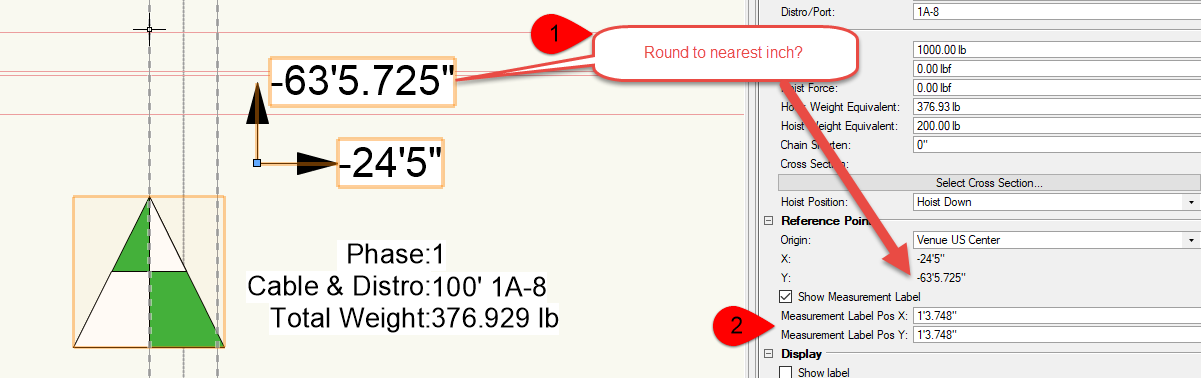
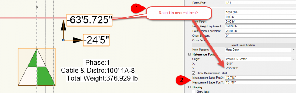
I am using the new Hoist tool in VW2021 and have two questions. 1)My measurement Labels display the location down to inches with 3 decimal points. Is there a way to round that display to the nearest inch? 2)Something seems wrong with the Measurement Label text boxes. If I type a value in the OIP box for the label Position the label moves in a way I don't expect and the number in the OIP changes from what I typed in. Lets say I want to move the label 6" from the motor or approx half what it currently is. When I type -6" in the X position it moves the label to a new location of -14'2.136". The label moves way to the left on the drawing. I would like to be able to select a number of motors and adjust all of the measurement labels at the same time. If I click and drag the label it works correctly, the OIP display is correct based on where I dropped the label, its only when I enter values into the OIP that I get un-expected results. This feels like a bug. Thanks for any advice you all can provide. Neil

-
Wow both really great suggestions. Thank you!
-
I am looking for some best practice advice for showing power layouts on our drawings. What I would like to do is quickly and easily drop a symbol on a plan view of the drawing indicating where 15 or 20 amp power drop circuits are needed. I am not really looking to sort out cable length or path, just where the power drops are needed, and have a way to print it that is easy to view and understand. This seems simple at first, what I am really struggling with is how to deal with different scales of drawings and the symbol. Sometimes we are in a 40x40 ballroom and other times we are outside in a park (much larger). If I draw a symbol for an outlet that is say 1' x 1' and drop it into the ballroom then print a ballroom overview on a reasonable size piece of paper it is a good size and easy to interpret. If I take that same symbol and start laying out outlet locations in the park example the symbols are so small you can hardly see them when the scale is zoomed that far out to fit on a piece of paper. I don't really want to have to re-draw the symbol to get it to visible scale/size for each different drawing. So, am I better off drawing on a design layer? Maybe the design layer with outlet locations is a different scale than design layer with the site layout? Is there a tool or plugin that does something like this already? Is the best practice to do this in annotations on sheet layer? Any creative solution to this that I am missing? Thanks for any wisdom the group can provide. I am using VW spotlight. It seems like the there might be an outlet tool in the MEP version according to some other posts. Is this available in VW spotlight? I can't seem to find it.
-
Get Connectors - All connector locations reset
AceRoehrborn replied to AceRoehrborn's topic in ConnectCAD
Awesome! Lots of great ConnectCad improvments in SP3 -
Awesome! I thought I had something screwed up in my drawing. Thank you!
-
This seems to be fixed in VW2021 SP3. The titles not longer wrap when text align is set to above. This works great!
-
I just updated to VW2021 SP3. Was working on cleaning up a drawing and I am noticing that all my circuit numbers are disappearing off the schematic when they are connected to a CTP socket. Circuit connected to device sockets seem fine. I also have two wires connected to the same socket on a device. Previously the circuit numbers would both show on top of each other. Now they both disappear. It seems like there may have been some logic added to cause the labels to disappear if the drawing gets cluttered or the labels are overlapping somehow. I can't seem to figure out what is happening and I am getting mixed results. See attached image. Why does the circuit number N10 not appear on the "out" but it does appear on the "In" ? Is my theory about something going on behind the scenes hiding these numbers true? Is there anything I can do to get my circuit numbers back?