mike m oz
-
Posts
4,876 -
Joined
-
Last visited
Content Type
Profiles
Forums
Events
Articles
Marionette
Store
Everything posted by mike m oz
-
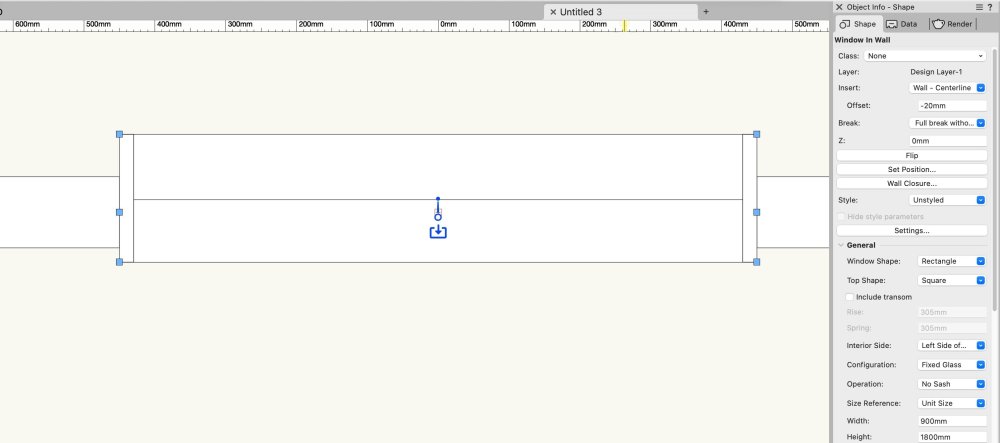
The offset needs to be -20
-
Parking Spaces - Dimensions at 45 degrees
mike m oz replied to Michal Zarzecki's question in Troubleshooting
Please Bug Report it. It is an anomaly that has been previously reported.- 1 reply
-
- 1
-

-
Spotlight doesn't have the Hardscape tool. Theatre4jc's request is a very valid need for Spotlight users.
-
Customizing Cabinets in Vectorworks 2024
mike m oz commented on Rob Nykolaishen's article in Knowledgebase
Essential quality information. -
Claes, how does that compare quality wise to Nomad?
-
Ando style concrete formwork hatch (metric and imperial)
mike m oz replied to mike m oz's topic in Resource Share - Hatches
Took a while, but I found them. Ando concrete formwork hatch & tile imperial v2011.vwx Ando concrete formwork hatch & tile metric v2011.vwx -
Ando style concrete formwork hatch (metric and imperial)
mike m oz replied to mike m oz's topic in Resource Share - Hatches
I'll need to hunt through my old hard drives for them. -
Have you tried drawing it with the Hardscape tool using the Path Mode for the roadway parts. The Roadway tool can also be used. I'm not sure how you could model the flared and portions with different radii corners on each side.
-
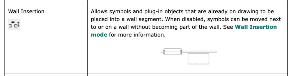
Doors can't extend past the end of a wall so you will have to create Openings with the Door Tool in the separate walls and then manually place the door into the opening created. Make sure the Wall Insertion Mode is off when you do that to prevent it inserting it into one of the walls. It might also be prudent to give it a unique Class and temporarily switch the Class Options to Show/Snap Others.
-
I've seen this problem before. Try clicking on the inside for the problematic segment and see if that offsets it outwards. Can you please bug report your problem.
-
You will need to create your own gate pair symbol. Duplicate the existing symbol and then mirror the gate parts.
-
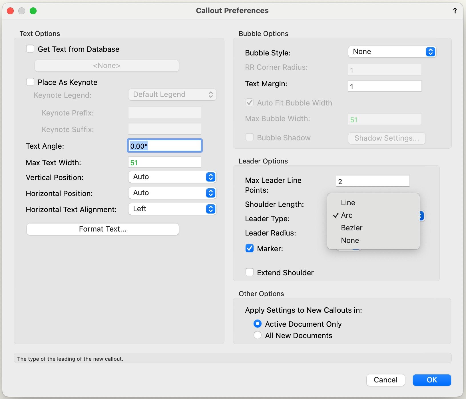
Give us curved leaders on callouts.
mike m oz replied to Bruce Kieffer's question in Wishlist - Feature and Content Requests
Bruce, there is already an arc option.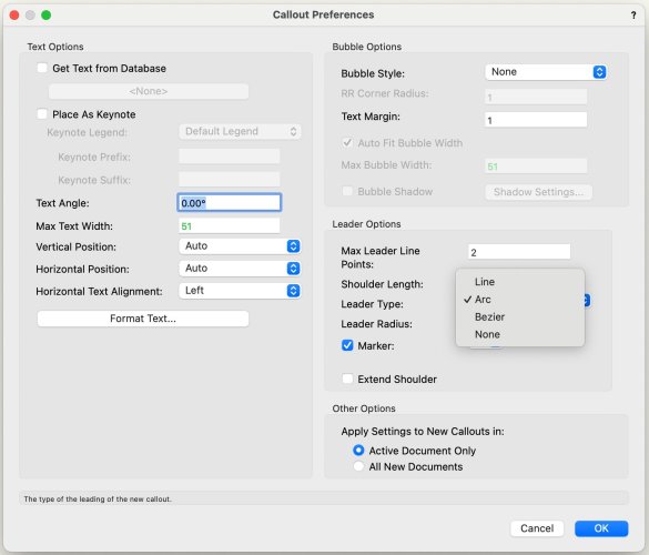
-
Go away – Component Edit palette!
mike m oz replied to Kaare Baekgaard's question in Wishlist - Feature and Content Requests
Kaare, can you please post a contextual image of which palette you are referring to. -
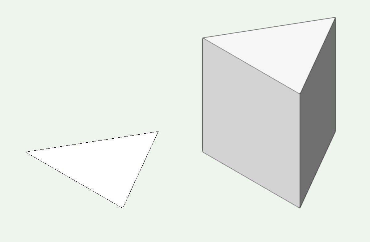
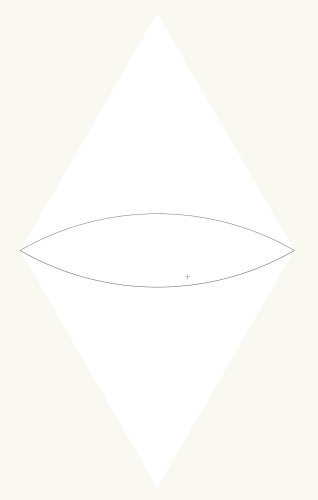
If you draw a triangle using the Triangle tool then both the Extrude command and the Push/Pull tool can be used to give it a third dimension.

-
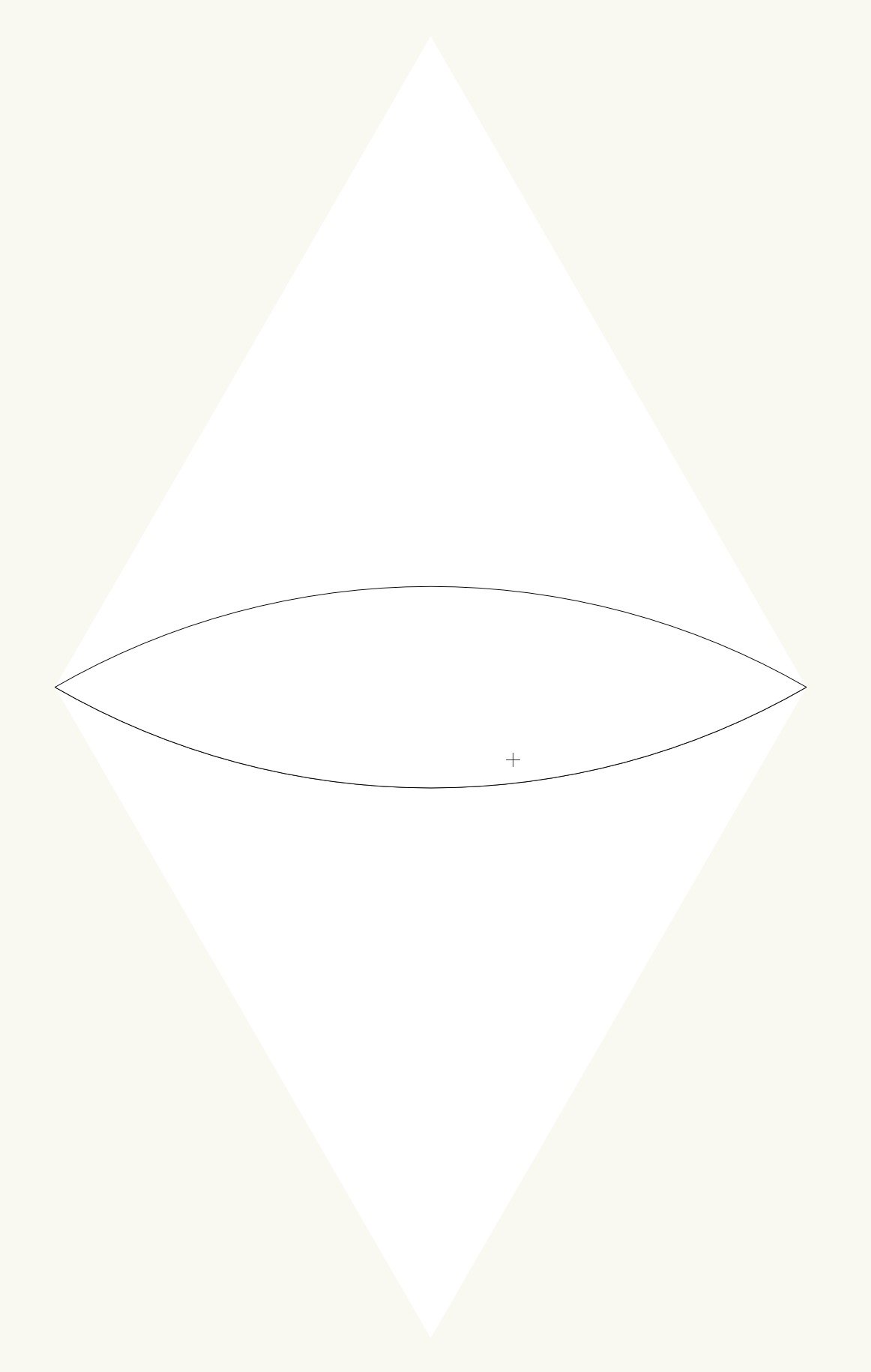
Pat Stanford's suggestion is the easiest way to do it. If the arc ends intersect the paint bucket mode of the polygon tool works.
-
The Non-Plot Class is created by both Door and Window Objects.
-
My observation from years of experience helping people sort out Vw problems. I've seen more than a few users tie themselves up in knots by setting their None Class to invisible or having its line weight set to zero or using a pen colour that matches the colour of their background.
-
The None Class is the equivalent of the 0 Layer in Autocad. You need to have it visible all the time including in every Sheet Layer and Design Layer Viewport. It also needs to have a pen thickness and a visible pen colour.
-
Three things to check: 1) Is your None Class set to visible on your design layers and your Sheet Layer Viewports? The None Class needs to be always visible. 2) Is your None Class pen thickness set to 0.00? If it is then that is why you can't see the leaf and swing linework. 3) Is your pen colour set to the same colour as your screen background? That would make the leaf and swing 'invisible'.
-
VW2024 NEW CABINET FEATURE - CUSTOM DRAWER DOOR HEIGHTS
mike m oz replied to Todd W's topic in Architecture
In the list immediately above you need to hilight the item you want to define the height of. -
Ceilings need to be a separate object type that can be horizontal, raked and vertical (for bulkheads). Their components also need to seamlessly join. We also need the ability to have walls automatically clip ceiling components so the structural cores join.
-
Make sure your Door object container Class and its component Classes all have fills. There is a Hardware tab in settings. Make sure Include Hardware has a checkmark against it and you have selected a Hardware Set.
-
Check Document Preferences to see if you have Enable legacy 2D features turned on and Turn on unified view turned on. Both should be set to off.
-
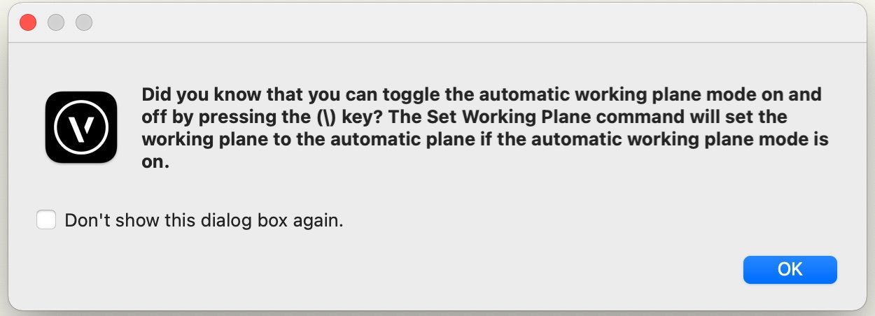
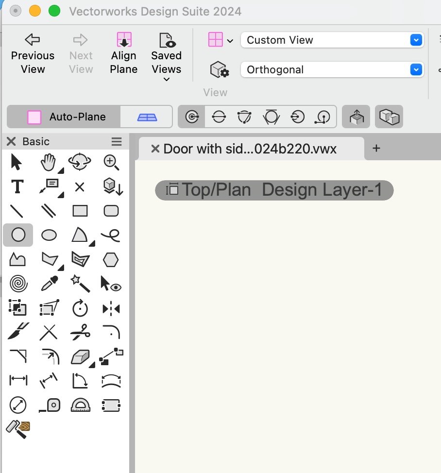
The Auto Plane / Working Plane toggles only activates when you have a 2D drawing tool selected. The Align Plane tool will give you screen plane. You can also switch the Working Plane mode between Layer Plane and Auto-Plane with the back slash key.

- 1 reply
-
- 1
-

-
Try deleting your User folder and then let Vectorworks create a new one when you restart it. In Vectorworks Preferences under the User Folders tab there is a Reveal in Finder button.