-
Posts
291 -
Joined
-
Last visited
Reputation
79 ExcellentPersonal Information
-
Occupation
Director/ Principal Landscape Architect
-
Homepage
https://larchconsultancydesign.co.uk
-
Hobbies
Nature, sustainability, biology, nature-based solutions, DIY, design
-
Location
United Kingdom
Recent Profile Visitors
The recent visitors block is disabled and is not being shown to other users.
-
For example, in my case, I launch AI Visualizer and when I hit Generate nothing progresses and the Wheel of Death goes on and on. I still can close the Visualizer window but when I reopen it it still revolves. I need to relaunch VW to get back to normal.
-
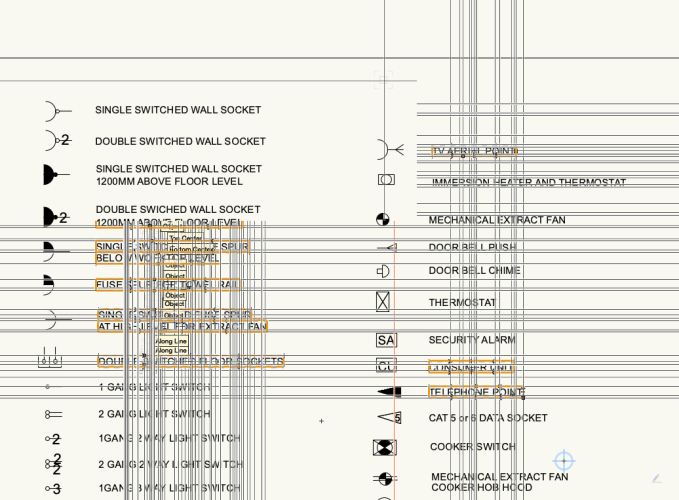
Hi All, I have just started experiencing odd and very distracting behaviour from my coursor. The crosshair duplicates along the mouse movement path populating the portion of the model space to the extent that it becomes illegible. Relaunching VW helps only for a short while before the problem returns. It also affects all open files - it's not an issue with a given file. Any ideas?
- 1 reply
-
- 1
-

-

Exporting Shapefiles from Georeferenced Files
Michal Zarzecki replied to lisagravy's question in Troubleshooting
@Shane W, whilst working on a project today. I managed to export my site boundary and what I needed and then I was able to import it all to QGIS and Google Earth Pro. I used <Object without a record>, 'Selected objects' and 'Write projection files'. It flashed something about an error in the process but otherwise produced a usable shapefile bundle. I hope you will succeed as well but I also hope that this matter will get some attention and help/ guidance information produced. -

Test Proximity and Text to 3D Loci
Michal Zarzecki commented on SBarrettWalker's file in Marionette - Networks
I face the same issue but in the metric system. It is ok if the topographical survey plan is in metres and the drawing is set up for these units accordingly. When the drawing is in millimetres, Once imported, I switch the units to metres; run the Marionette script and turn back to mm. Nevertheless, it would be good to know what node to insert to convert one unit to another, e.g. metres to millimetres, by multiplying by 1000. I was looking into Simple Maths nodes, but Mul requires values from two other nodes - as far as I understand. I am sure it's easy when one knows what different nodes do. Any help with this? -
Hi All, How can I export only simple geometry to dwg, ie without all the shx files needed for complex linetypes? I am sure I didn't have that problem in previous versions but now, everytime I export I have loads of those shx files I need to delete from my folder. I don't want to save the linetypes as blocks either - just simple geometry for other team members.
-
Hi All, I received a SketchUp massing model from an architect. When I try to put it on my site model, it seems that the meshes of different buildings have different reference points for their Z-values, ie. some are at the base and some at the top of the mesh. How to change that? I tried editing the mesh and moving it up or down to - what I thought would be - 0, but this just changes the Z-value. Any experience with that?
-

Curb Lines along Parking - best tools/methods
Michal Zarzecki replied to Phillip Tripp's topic in Workflows
I use the Wall tool for kerbs and edges. By manipulating the top vertices you can taper the wall to represent drop kerbs. I have mine saved as styles representing edges (thinner) and kerbs of different heights (1, 2 and 3 type; UK). An improvement would be to be able to add custom profiles to reflect specialist kerbs and different applications (like half-battered, splayed etc) -
@Benson Shaw, This is what I have been trying to do but it doesn't seem to work in 2023. It's the same computing error. And I fully agree that there should be an easy way of measuring and reporting volumes of selected areas. How should we do our job otherwise - invest in a dedicated software? It kills the purpose of VW and its USP.
-

Why site model cut and fill appears only in wireframe?
Michal Zarzecki replied to Zsombor's question in Troubleshooting
Very interesting insights guys. Thanks a lot for your thoughts on this one @Jeff Prince I noticed today in my model that the attributes I set up for my 3D Cut and Fill Volume don't work. I have classes set up for all Site Model components, with attributes set to Use at creation. Then in the Site Model graphic attributes I have all those classes mapped correctly and everything is set to be by class. And yet, it doesn't seem to work for the 3D Cut and Fill Volumes. I need to change these two manually. Everything else seems to work by class. Any further thoughts? -

Content of Viewport in Sheet Layer Not Showing or Disappearing
Michal Zarzecki replied to Michal Zarzecki's question in Troubleshooting
In my case all sorts of things tend to disappear randomly - even the title block! I will have to get in touch with the Technical Support because I cannot work like that. -
Hi guys, I have a question relating to this topic or tool mode. I would like to use this mode to create a ditch with sloping sides. I have a model with Grade Limits and I have created a path acting as the bottom of my ditch. What I don't understand is why this creates a linear depression with vertical sides rather than sloping gently from other levels. Am I doing something wrong?
-

Content of Viewport in Sheet Layer Not Showing or Disappearing
Michal Zarzecki posted a question in Troubleshooting
Hi Guys, I just noticed strange behaviour in viewports in a sheetlayer. I am using another VW file with an imported DWG geometry as an xref. All classess and layers visible. In my model, I created a viewport to reference to my xref file, normal stuff. I then created a viewport showing the site with the xref and I put it on a Sheet Layer. Initially, the problem seemed like one class - showing a footpath - being switched off. Gone. But everything is alright in the Design Layer. Nothing is switched off. Out of patience I deleted that VP and created one from scratch. All visible. When I copy that new VP or create one from scratch, the content disappears completely. It flickers only when hitting B-key or when moving or zooming in and out of the VP. When plotting to PDF, everything is in place. Any suggestions? A bug? Graphic processor issue? I cannot work with that. Quitting and relaunching doesn't help. Screen Recording 2024-05-16 at 13.44.52.mov


