theatre4jc
-
Posts
27 -
Joined
-
Last visited
-
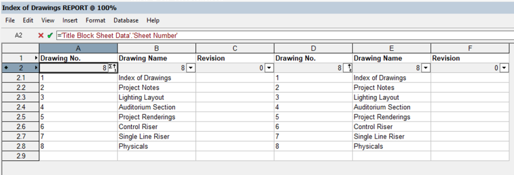
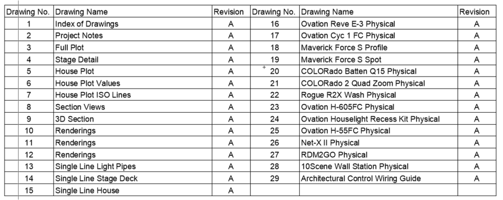
I am trying to create a database worksheet that will automatically show an index of drawings for a project. To do this in a single set of 3 columns (A,B, C) is done and works correctly (but needs cleaning up). However many of my projects use more rows than the page has room for. So I want to have two sets of the same function. However I would like to organize/sort so that Column A is limited to 15 lines max and then spill over into Column D for the next 15. The names and revision would have to follow as well. I cannot figure out how to do this, or if it is even possible. This is pulling from the title block sheet number for automatically filling. Any tips on the possibility of this? Can a these formulas be filtered like that automatically? What I currently have: What I want it to look like: (manually built)
-
Section/Hidden Line Improvements
theatre4jc posted a question in Wishlist - Feature and Content Requests
Every time I try to create a section viewport using the View->Create Section Viewport command, my computer becomes completely unusable for 30 min-5 hours depending on the model. It attempts to render the viewport, however I just see a black screen for a long period of time. Computer was purchased with multiple processors (not the specs I requested), however when rendering Hidden Line, it seems like only a single processor is being used and unfortunately for me, the computer assigned to me is not strong enough on a single processor. When needing to annotate my Hidden Line Sections it takes a full day, just to create the viewports needed. God forbid I need to make an additional change... Something has to give. Other render styles that can take advantage of the multiple processors are fast and effective. Just Hidden Line. No matter the settings used and even on the simplest of show files. -
Creating a sloped floor is very annoying and difficult. When drawing a simple rectangle, it's not to bad, however when there is any kind of curve to the seating it's a huge pain. Many theatre and house of worship venues have curved seating areas with raked seating on a slope. It would be great if there was a dedicated tool that was smart enough for when the floor is drawn and a minimum height is put in and a maximum height is put in, the slope and angle is properly placed. People always suggest the drainage tool. If that is really the best option, maybe a dedicated training video that specifically shows how to do a room that has a curved back and multiple fall angles for the sloped floor.
-
Now it gets really weird, I changed nothing but updated the viewport again and suddenly everything works...
-
I have an odd one that I cannot figure out. I'm making Sheet Layers from Cameras and on one sheet the gobos from the lighting fixtures are visible and in the next layer, the gobos are gone. The render settings, layers on/off, and classes on/off are all identical. I cannot figure out why the textures would disappear. The really weird thing is in one version of the project they were there, and in the next rendering they disappeared. When I go to Edit the Camera, the gobo textures render properly, but they are gone on the Sheet Layer. Can't figure it out at all. Thoughts?
-
Sorry for the multiple posts. Soft Shadows was freaking it all out. I turned off Soft Shadows for all fixtures with shutters and instantly everything rendered correctly.
-
I did not make changes to the instrument texture before this problem started. I did, however make changes while trying to problem solve. I did import in a default directional light because I wanted ambient light off, but still needed some light to model the house lighting. I can see the light but it has black specks throughout it in the render now. I have soft shadows on. I cannot get gobos to render I have tried copying and pasting into a new file and still a no go. When I did this I did not include the directional light. One thing I learned and did in my problem solving was figure out how to see the shutters in OpenGL. I can get this to work, however that will not help in the end because I need to show a full render. What is really confusing to me is it worked one day and then day 2 it didn't. Maybe I should try this in VW2020 and see if the issue follows the version. EDIT: 2020 didn't add the shutters but the light no longer showed the black specks throughout the render.
-
I am working on a design for a historical building where I have been asked to light some statues on the walls. They have asked to see a concept of this so I have taken a picture of the wall that was provided to me and placed it on the wall. Then fixture by fixture I used shutters frame the statues. I did not go through all the steps to make the shutters visible in Open GL. Instead I used Fast Renderworks and framed each statue out. Time intensive, yes, but it worked for my needs. I got every fixture framed as needed. That ended my work for the day. Saved and quit. Day 2, opened the file and selected every fixture, turned on (because I was doing this one at a time for render times the day before and they were off), selected Fast Renderworks to quickly check everything, and no shutter cuts were visible. Quite literally nothing changed except turning on all lights. Going back and doing one at a time and no shutter cuts are visible. The Object Info Pallet is showing the shutter cuts properly. I tried adding in my Renderworks background and style that I always use and doing my custom renderworks and still no shutters. What could cause this to suddenly disappear? Is there a specific way to render shutter cuts in a custom rendering that I may be missing? Unfortunately due to NDAs I am not allowed to share the file or screen shots which will not help in problem solving. Using VW2021.
-
I've got an old file that I've been updating and cleaning up some. It had fixtures from many different years of VW and I wanted to update to the new GFDT fixtures. Did this and when I tried to do a MVR file none of the fixtures show up in Vision. No Patch, nothing. However, if I export ESC everything is there and working properly. I use my own Vision Mapping Data for addressing in VW19 and tried changing that back to the default to see if that was the issue, and still nothing. Class visibilities are correct and on, so is Layer visibilities. When I do the export to MVR I am getting a list of several custom lighting instruments that all correspond to the lights on the plot, however nothing comes through in Vision. What could I be missing?
-
This is extremely frustrating right here. We are trying to make our industry safer and work easier and a major manufacturer is unwilling to work with others. Yeah I'm trying to find out the weight of a Tyler Truss 12x18x96" stick and that's frustrating.
-
Thank you for your reply. Turns out I had updated Vectorworks, but failed to also update Vision and didn't realize that. However I did notice if I changed the units from Millimeters to Feet, or Inches, my lighting fixtures all disappear. I can leave in mm and they work just fine, just something I noticed on my file.
-
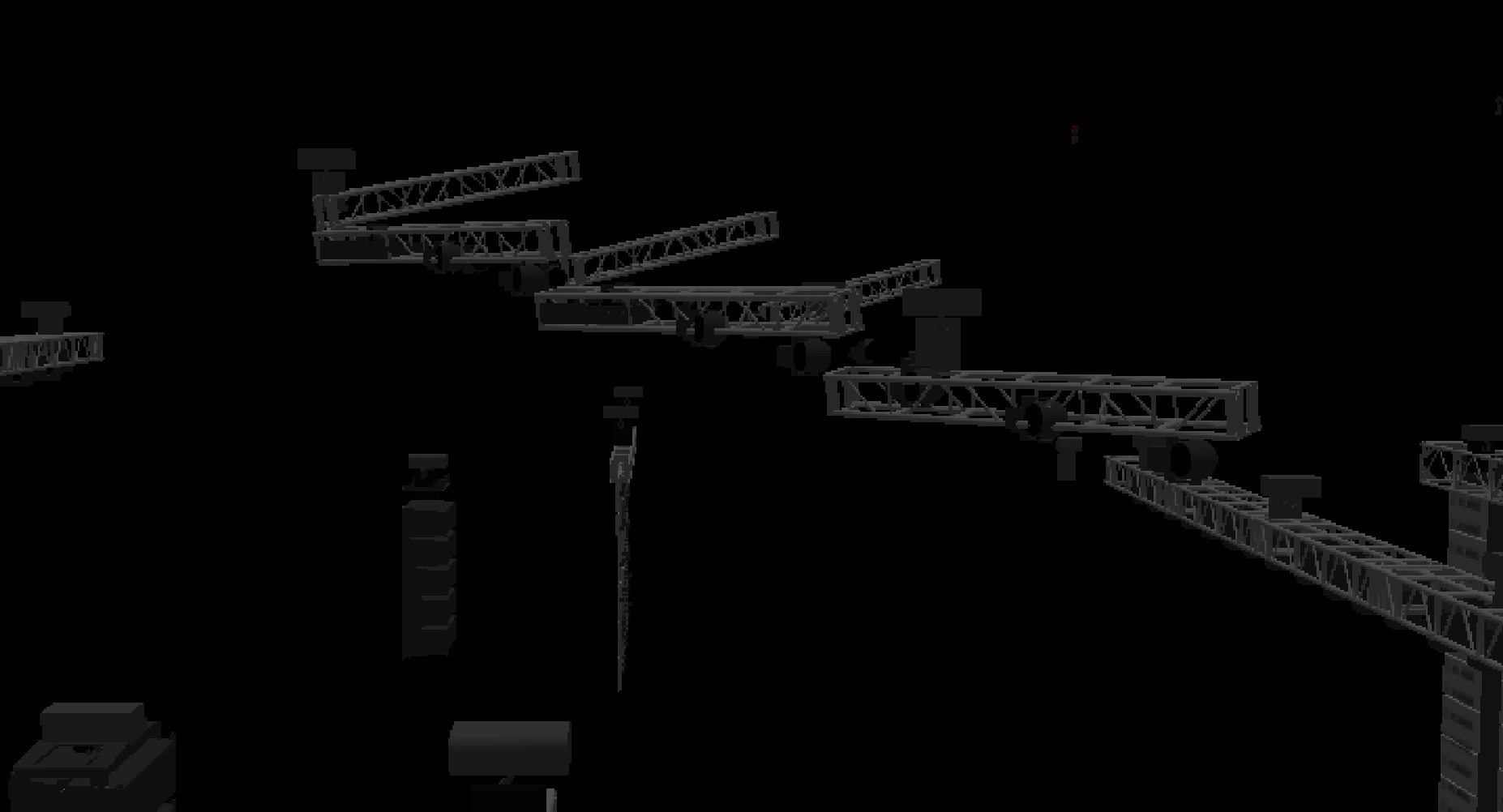
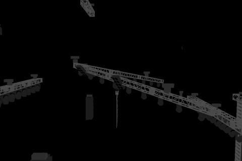
It's my first time exporting to MVR, I have a truss on a rake and when I Export ESC everything works properly and looks correct. However when I import a MVR file the rake looks like this: You can also see that all my fixtures have rotated and nothing connects properly. All fixtures are rotated funky and this truss no longer rakes as it should. When I exported I selected all objects and opening in Vision on the pop up window, after the first failed attempt, I played with the settings and still had no luck. Is there something I am missing?

-
I have a client that has made a request for custom set pieces lit with LEDs of some type. The set pieces will be simple to build using metal framing and plexiglass, but I'm not sure how to best draw this in VW. At first I was going to do a simple extrude and just make it the be a glowing color. But what I would like to do is draw the extrude with a LED fixture at the top and bottom to illuminate the extrude internally so that I can show it properly in my renderings. Issue I'm having is how to do a texture to mimic frosted plexiglass. The frosted glass textures that come with VW are to transparent and I couldn't find a texture that would pass the color, but not be able to see into the object. Any thoughts on how I could get this accomplished?
-
Is it possible to create a ceiling tile grid inside Spotlight, or is the tool only available in Architect? I looked but couldn't find it and didn't know if I was just missing it and being stupid or if it is just not possible? I've been asked to speak into the can light placement for a space I'm doing production lighting for and didn't want to manually draft it out with lines, unless I have to.
-
I didn't realize there was a difference between your tools and the ones that got incorporated into VW. Just to make sure I understand perfectly (because it effects me wanting to buy them) The updates mentioned above to the Soft Goods 2 for specifying the weight of the drape is not possible in VW19? I've not updated to 19 just yet (waiting on IT who keeps the license) but if Soft Goods 2 estimates the weight I'm assuming that will allow the drapes to be incorporated into BraceWorks. Correct?