All Activity
- Past hour
-
 One of the benefits for designer vs Architect is (Landmark) It is a huge add to the Package plus 15 volumes for free of Laubwerk plants that costs alone around 2200 Euros beside the price for Landmark itself, The good news now that D5 render will release live sync plugin for Vectorworks, which will be a huge step to Visualize Vectorworks models as stills and animation in perfect way, and the latest news is that there is an agreement that has been signed between Nemetschek and Autodek for interoperability between All softwares from both companies.
 - Today
-
 SafeTilt joined the community
 -

Why are my fixtures outlines still black?
Jesse Cogswell replied to Iainy1961's topic in Entertainment
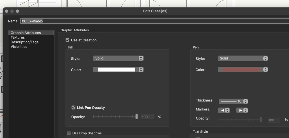
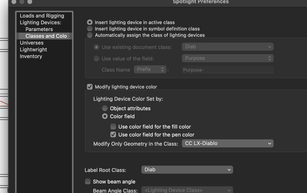
Those settings will pull from the value of the Color parameter in the Object Info Palette, not the color in the Attributes pane. Being that the Diablo is a moving light, you likely don't have information in the Color parameter, but I'm betting that you put a gel color in there (like R3310 to get at least close to the color you specified), the pen will change to match. The option that you will want to pull the pen color from the class settings would be to select Object attributes instead of Color field. -
I followed the procedure for changing the outline colour of my lighting devices but they remain stubbornly black. Any ideas of where I went wrong? Thank you
-
Thanks.
-
The NASA Maps (Blue Marble) have been there for a long time. (2002). They are great and you can use more than one. They are registered to overlay. If you notice the clouds. That map came from the Blue Marble collection and is intended to be used with any of the day or night maps. The blue hue is coloured light with radius decay.
-
If I understand you correctly, then yes. Use the Smart Edge snap functionality and enable Snap to Bisector. Snap to bisector.mov
-
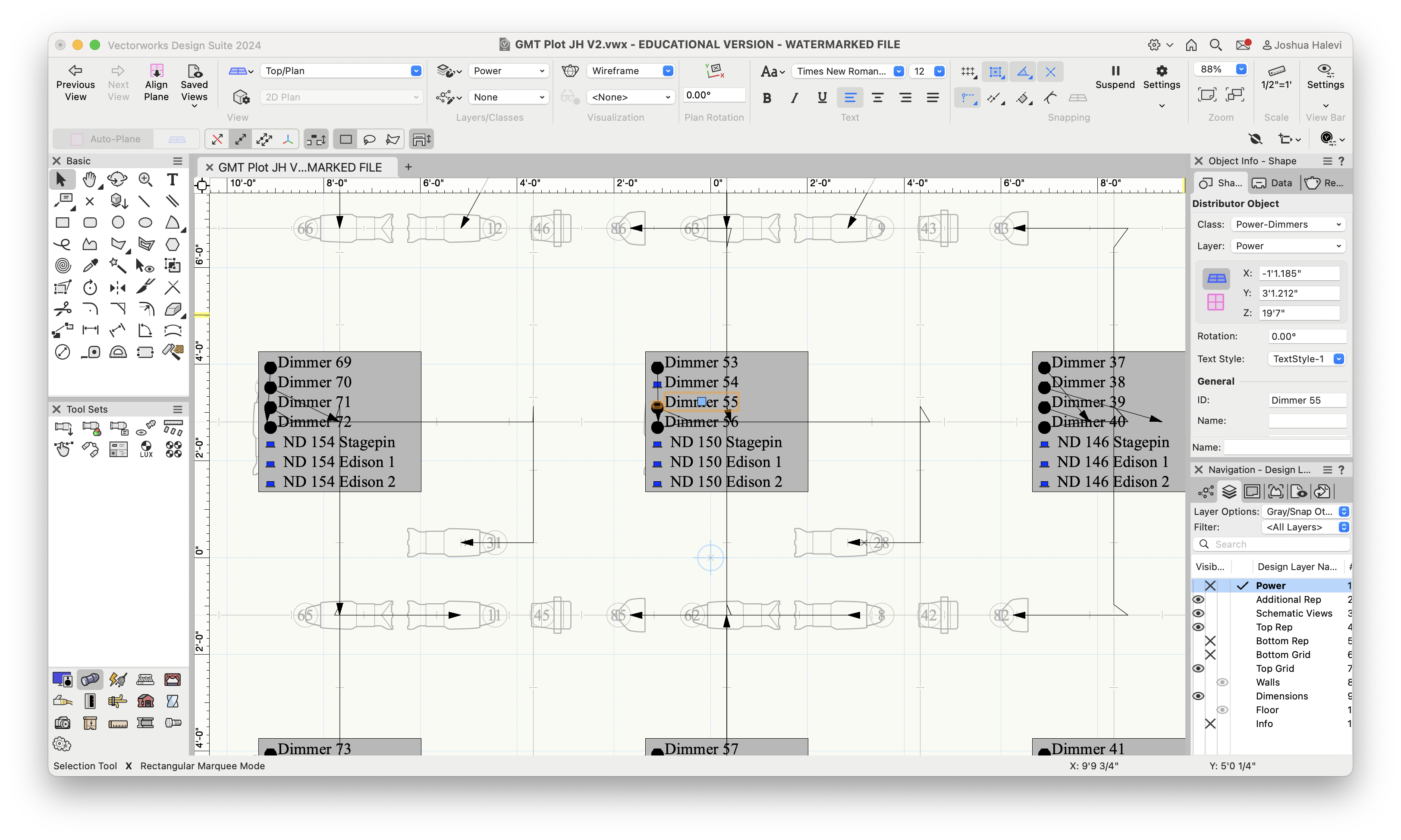
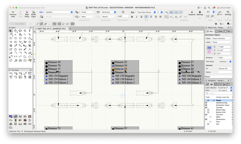
Updates: I created 2 distributor symbols with just a power out component, one of them stagepin and one Edison. Each dimmer output is then a separate distributor object. They are placed in 3 classes: dimmers, hot stagepin, and hot Edison. I've uploaded a photo. If people have any suggestions I would still love to hear them. Pros: - Connecting the distributor to the light fixture is fairly easy. I can click on the distributor object titled Dimmer 55 and then in the power information output dropdown select the channel I want to connect it to. From the fixture side it is also easy since each of the dimmers come up separately with a short name. - The black dot at cable start covers the symbol icon, which easily indicates if the dimmer is taken or not. Cons/Difficulties: - Had to place a lot of distributor objects and number them individually even though each breakout is the same. - Had to manually connect each distributor to the lighting fixture despite the fixture having a dimmer number parameter and the distributor object being named as the dimmer number. - The circuit name parameter in each lighting fixture is automatically updated to be the distributor name. In a worksheet this allows for double checking that it matches the dimmer number parameter. However it is one sided -- if I edit the circuit name in a worksheet it does not reconnect it to the new distributor. - No easy way to automatically connect fixtures to closest available dimmer? At least not as far as I have found
-
Is there a simple way to draw a line that bisects the angle between two intersecting lines on a plane? (im working in 2d for this in T/P view) I did a search in VW Help and in the Forum for "bisect angle" and it turned up zilch. Seems like a useful tool. I can figure out a kludgy way of doing it but it seems unneccesary. Thanks for any help.
-
Something like this ? https://blenderartists.org/uploads/default/optimized/4X/5/0/2/5029a48052f6f91a399a41dcd1004adf854b17ea_2_1380x690.jpeg
-
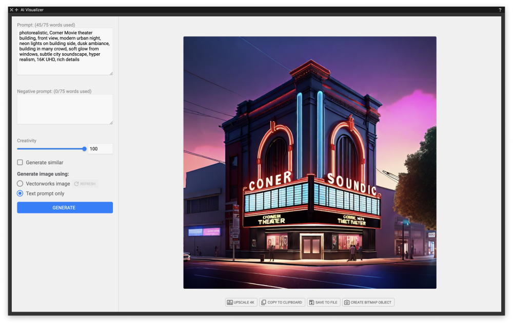
I am always intrigued by the creativity of the facades of Movie Theaters. I think I'll give this AI a go. For better results, create a simple base model to land the camera view. It takes several tries.

-
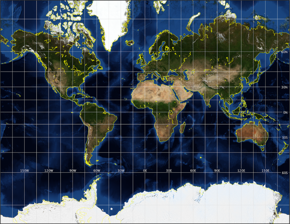
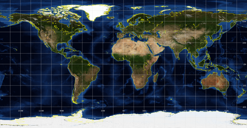
Thank you, that was just a quickie mocked up in Affinity Photo. I exported rendered images from Vectorworks, imported into Affinity Photo, added some outer glow to simulate an atmosphere/get them to pop off the background, and added a background and text. You could do the same in Affinity Designer or the equivalent Adobe products. I converted my workflow to Affinity from Adobe due to the subscription plan offered by Adobe at the time. That's pretty good. The problem is you used a map using Mercator projection that does not include the entire surface of the earth. Here is the image you used in your texture: And here is what you actually need per my original example... an equirectangular projection. Note the difference? 1. It includes the entirety of the earth's surface 2. It uses the projection compatible with spherical mapping. *** This image is not in the correct proportions, it is an illustrative example for the purpose of discussion, go grab an image from a source you trust. I picked this because the graphic style matches the one you posted and would allow people to focus on the difference in projection. This is basically what a globe would look like if you mounted a camera to a tripod focused on the equator and rotated it, ie cylindrical projection or in cartography... Equirectangular or Equidistant Cylindrical. If you use any other type of projection, it's going to fail when using a spherical mapper. I encourage everyone perplexed by this thread to read up on https://en.wikipedia.org/wiki/Equirectangular_projection or you could google "flat earth" 🙂 You can source accurate textures from NASA at the blue marble collection: https://visibleearth.nasa.gov/collection/1484/blue-marble?page=1
-
Hello all. My apologizes if this has been discussed before but..... Trying to export a simple 2D drawing (VW 2024) to be an eps file. But every time I do, Vectorworks crashes after creating an .eps file with zero bytes. Anyone else having this issue? Thanks. Adam Vectorworks 2024 (Update 4.1) Macbook Pro (Apple M1 Pro) Ventura 13.2.1
-
That is why I had searched for an already textured Mesh Globe. Something like a 3DS, which VW can import. Usually the Mesh keeps the initial Mapping. (At least VW always resets it when you try to edit the Mesh) But in a 3D App I would also have tried a simple Cylindrical Mapping. Which should work if you have a distorted rectangular Map. (Like a world "map")
-
Looks great. Good work on the texture. What texture map did you use?
-
@Niccinator I looked into extending functionality to Referenced Viewports this morning, and I don't know if it will be possible. Referenced Viewports are not exactly Viewports per se, but a Plug-in Object called "NAA_DesignLayerViewport", so the standard Viewport functions may not work on them. The larger issue is that I would need to pull classes and layers from an external file. I know how to do that, but not how to get the full path to the referenced file, just the filename. I would also likely need to write a completely separate plug-in for this, as the process for getting and storing classes and layers are completely different between external files and the local file, as I'd have to generate a new list of classes and layers based on which viewport was selected. I am a little busy for this upcoming week, but am planning on taking some time off later this summer and could look further into this at that time.
-
 andyegan-strix joined the community
 -
 He has great taste in music with these videos.
 -
EAP, Multiple Planes, Radiused Corners
LavenderGardens replied to Ed Wachter's topic in General Discussion
how are you snapping to the face of the rectangular geometry? When I try that I just get a 2d line even when I using the 3d polygon tool. -
Okay! Thanks for all the input. I ended up making my own texture and putting it on a sphere. Here's what it looks like. I'm still working a little on the scale, but otherwise.... Globe.vwx
-
Beautiful work. How did you make your board showing the three views of Earth on the star field? Is that Vectorworks too?
-
'Proposed Contours' not working as expected in Site Model
LavenderGardens replied to nicovlogg's question in Troubleshooting
You make it look so easy! How long did it take for you to become a wizard?- 9 replies
-
- 1
-

-
- site model
- proposed
- (and 3 more)
-
A lot of us have been asking for this for years. Other software does this, why not Vectorworks?
-
 johndoe1302 joined the community
 -
I can open vectorworks and thats about it. It just freezes up and stops responding right after that. I have all the minimum system requirements to run it. My drivers are updated. Still nothing My specs are the following: Intel(R) Core(TM) i5-7400 CPU @ 3.00GHz 3.00 GHz 16GB RAM GTX 1060 I need this software for school so any help would be great thanks!
-
Definitely a great addition! Now I don't need to create an invisible threshold to achieve the same thing... But presumably you wanted to offset the leaf in plan rather than elevation in your original post? Perhaps this is functionality VW should also add. I made a couple of wishes in a similar vein for the Window tool recently:
- Yesterday
-
Also - If hardscape 3d display curvature is is changed via the simplification tolerance, a double click of the Hardscape launches the Reshape tool and reveals vertices of the Path (no need to right click>edit path) for edit - not converted to some polygon with many facets. Edits can be made in 3d views as if editing that simple 2d polyline. Changing the Simplification Tolerance in the OIP does not affect the vertex count near bottom of the OIP. eg in my example above, the vertex count is 8 in each iteration of the simplification value. -B
-
Ok. Then I paste the symbol back in and then save that file to my favourites or wherever. Thank you.