All Activity
- Past hour
-
Hello, So the first thing I'd go ahead and look into to make sure everything is okay is the record formats attached to the barn doors and the fresnel. Since the barn doors are an accessory, you should NOT have to do all of that alignment. The accessory needs the light info record with a "static accessory" device type. Then you need to assign it as a "lens" accessory in the parts manager. Lastly, you'll need to make sure the 3D geometry in the fresnel has appropriate assignments in the parts record. You can find out more info here: https://app-help.vectorworks.net/2022/eng/VW2022_Guide/LightingDesign2/Concept_ Lighting_accessories.htm Secondly, If you're trying to make a new symbol, I wonder if duplicating the fresnel and then modifying the 3D geometry might be a good way to start. Anyway, that's all for now! I hope this helps!
-
 Nii Lartey joined the community
 - Today
-

Create section viewport and create viewport from clip cube not working
Chris J Clarke replied to Amber Hine's question in Troubleshooting
I’m having this problem now too. All of my Clip Cube Section Viewports are just blank. It works fine in an old backup of the file, but I can’t lose 2 weeks work by going back to that. I’ve tried everything in this thread to no avail. If anyone can help, then please let me know. I’m pulling my hair out! -
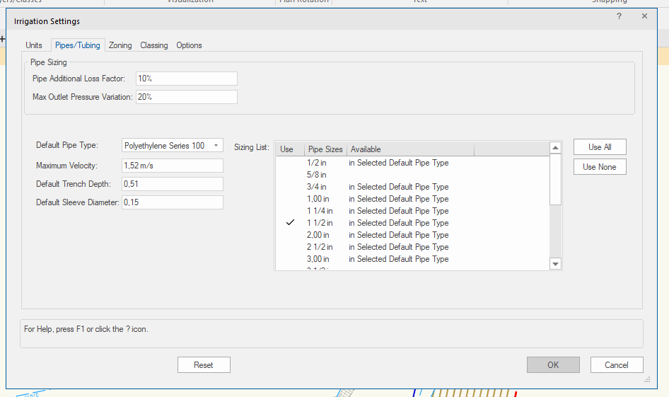
We're developing an irrigation scheme and faced a potential bug in the 2024 version of the software. To work in old projects we still have the 2022 version installed and, as you can see, there is the possibility of adjust the piping preferences following the typology Main Laterial and Drip: In the 2024 version that Tab disappeared: In the project that we are working the default pipe type only applies to the Main Lines, the Lateral Line don't follow the selected preference. That wouldn't be a problem if the project has almost 3000 pipes and 3km of extension... When we try to change manually, the software crashes... So we need to do manual confirmation on the calculations, a waste of time and money... Anybody faced this problem? Any solution besides a bug report?

-
I like it!!
-
Thanks!!
-
Here is one Corb did in an earlier version of windoor...

-
Yes many 2D tools now have 'Push/Pull Mode' + 'Push/Pull Combine Mode' which I don't think were available in VW2021. I don't know what version you're using as you don't have a signature. But I don't think anything described in this thread is particularly complicated, just several different options for achieving the same results. How would it better be done? I'm not familiar with any other software.
-
To me this is unbeleviable that clipping 3d-objects is actually this complicated. Is there not any updates on this in the 2024 version?
-
It is very straight forward for a flat LED panel to do a curve. How do we in Vectorworks to allow LED Panel itself that can be flex like ROE Topaz according to the curve, this will then allow us to draw accurately the handing frame we need to customised.
-

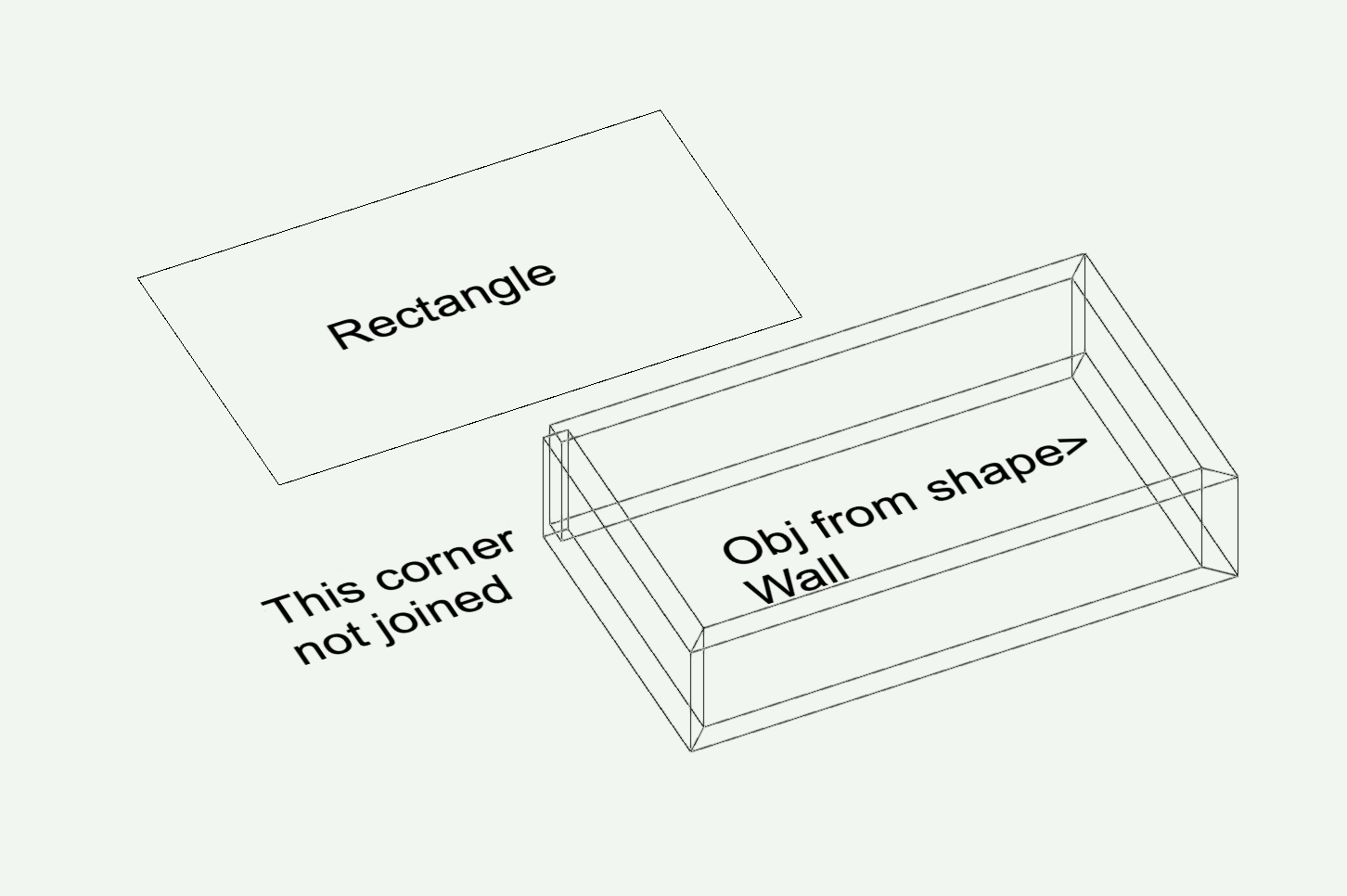
Rectangle to Walls - always one unjoined corner
Tom W. replied to Benson Shaw's question in Troubleshooting
I never create Walls this way but have tried just now + it is working fine: all corners joined when source shape is a Rectangle. I tried different Walls + different offsets + was the same each time. Not sure why it's different for you...! -

Accessory 2D Component Default Insertion Below Parent 2D Symbol?
aheininen replied to Martin Benesh's topic in Entertainment
Hi I shamelessly use this opportunity to plug in my previous thread with same kind of subject about placement of accessories. Any info on this @Scott C. Parker ? When I tested your file, Martin I could not find a way to get stand to be below Light Device. -
When I use Reality Capture > Point cloud on site to scan rooms/buildings I end up with randomly-named .pts files which get added to an increasingly long list in my Nomad Files + the only way of identifying what's what when I get back to the office is to go through them all examining them individually which is stupid. Because I use an iPad without a SIM card I don't have access to the Add > New folder option when on site, otherwise I would create a folder + save the scans there which would obviously make life a lot easier. As it stands I have to remember to create a folder before leaving wifi range which needless to say I never do... I thought I would make some 'blank' folders ahead of time so that I would always have access to them on site but Nomad won't let me rename them after creation. Why is this? Likewise I can't rename any of the .pts files into something more useful or move them into new folders. Is there a better way I should be doing this? I am pretty ignorant when it comes to all things cloud/syncing related. The files stored within Nomad I can also access via the Mac Files app but again there I don't have the 'Rename' option + can't drag files into folders. Then there is the Vectorworks Cloud Services folder on my desktop but this is something different right...?@inikolova? Thank you!
-

.las & .laz import problem with VWX 2023
Benson Shaw replied to Jeff Prince's topic in General Discussion
FYI, for MacOS - opening LAS or LAZ file in CloudCompare and port back out as LAS does import into vwx. Scale and location are wrong, but can be adjusted. -B -
Draw a layer plane rectangle. Objects from Shapes. Creates 4 walls, but one corner is not joined. Work around is to start with or convert to a polygon, but why doesn't the rectangle just make the join at all corners? -B

-
- Thanks for the feedback. We are already working on separating the scaling from the snap grid so that such issues will not happen in the future.
-

Default Circuit Graphics not showing text
Nikolay Zhelyazkov replied to DDIAMOND's topic in ConnectCAD
- About the wrong formulas, the old syntax was to get this data from the circuit but the new syntax is to get it from the device/socket directly. So please, use the UI to create your formula to ensure that it is valid. I think that the UI should be easy to understand and use. -
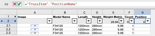
Hi all, I am trying to get a total weight load of a hanging position Autoplot seem to be well liked by many for this but I have some items that display the weight load in gram event though the header is KG thus i was trying to use a position summary to get fixtures counts with load and also opening the Hanging position to select all the truss elements to paste the HP name in the truss position name field. So if this works out properly, i can make a worksheet summarize by position name and length with total count However, it appears empty when i put it on a worksheet Any idea why so?

-
 It’s hard to visualise. Can you upload a file with just those two objects?
 -
Pat - just realized I never replied to this. That was exactly it, thank you!
-
 Thanks Mark, I did this initially in both the 2D and 3D, as well as adding the parts record to the accessory and checking "base". I've also tried alternating deletion of the two loci to see if one was affecting the other, as well as playing around with different parts record piece options, to no avail. The objects offset successfully, so I know it's trying to "do what I asked it to do", but the lighting device offsets on the z-axis to meet the 3D locus of the accessory with the light's insertion point and the accessory offsets on the y-axis to meet the light's insertion point with the accessory's locus location. Does that make sense?
 -
In order for the function to work you need to have also added the Parts record to the locus and checked “point”. You need to do this in the 3D component of the symbol. If you have 2d geometry then you need to do the same there as well.
-
Have some epix strips facing downward fanned out. When I use the mirror tool, the new selection gives me the right fan out but the fixture is upside down..any time I play with any XYZ rotation it doesn’t give me the results I want..any simple way to fix this?
-
 ramiroflores joined the community
 -

Vision_About GDTF Blade(Shapers)
haehyeonhong replied to haehyeonhong's topic in Vision and Previsualization
It hasn't been possible for a very long time. I want to work this out. Please help. -
There is a lot to talk about here. AI is likely the next Smartphone, it is already ubiquitous, we wont be able to live without it in 5 years. And, as consumers, users, and creators, we have to make some demands. We have to have transparency on how the AI models are trained. We will have mechanisms to monetize the use of AI and we must be required share royalties with the sources that helped train the model. Then, in the spirit of @Jeff Prince, make the machines do the mundane. Please don't democratize creativity.
-
Hey there good people, So, long story short, I'm super new to Vectorworks. The thing is, I'm trying to learn as much as possible about terrain modeling, site modifiers, retaining walls, and so on. As such, I'm trying to recreate a project I found online, which is situated on very steep terrain. Accordingly, I used some site modifiers to create planar pads for future construction. However, I'm trying to adjust how the pads and the terrain meet, so I was planning to use retaining walls. When trying to do so, I encountered the issue that in some places the wall must be on a slope, meaning it will need to be curved in some parts, straight in others, and with different heights at the beginning and the end. So far, I haven't been able to achieve what I'm looking for, so I was wondering if somebody could share a viable process? I'm trying to make it as realistic as possible, but I know I'm still lacking a lot of knowledge, both in the architecture field and in Vectorworks. So, as I said, any help will be incredibly appreciated. I will attach a couple of screenshots so my intention might be a little clearer.