aheininen
-
Posts
70 -
Joined
-
Last visited
1 Follower

-
Could not say it better myself. Well written Stefan.
- 1 reply
-
- 1
-

-
Hey @Peter Neufeld. any change to reupload your file for a test spin. Now link just says "Sorry! We could not locate the item you are trying to view."
-
Modeling Additional Slings for Rigging Attachments
aheininen replied to stayathomedad's topic in General Discussion
I would like to have that template file with curves. NURBS is one area I lack skill's to perform drawing fluently, any help there is huge to me. -
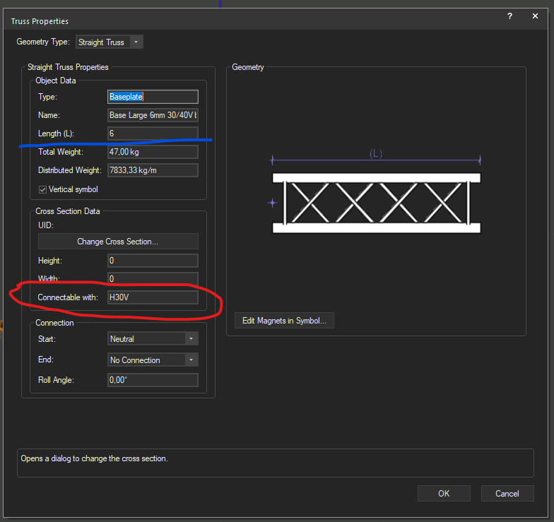
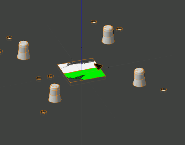
You need to input Length also Also remove second magnet from symbol, just leave one level with baseplate top plane. Look example from VW library Prolyte H30V baseplate.
-
Found the source. Thanks a lot @bsiegel
-
I am interested of that documentation. Even modifying hinges were a bit try and fail until you succeed method. Comparing how other symbols from library were constructed helped too. I'm sure documentation would be a lot of help.
-
This is what I refer to when I need to add lens glow. Author and source unknown( more specific, I can't remember), saved from these forums most probably. Spotlight Rendering Cheat Sheet.pdf
-
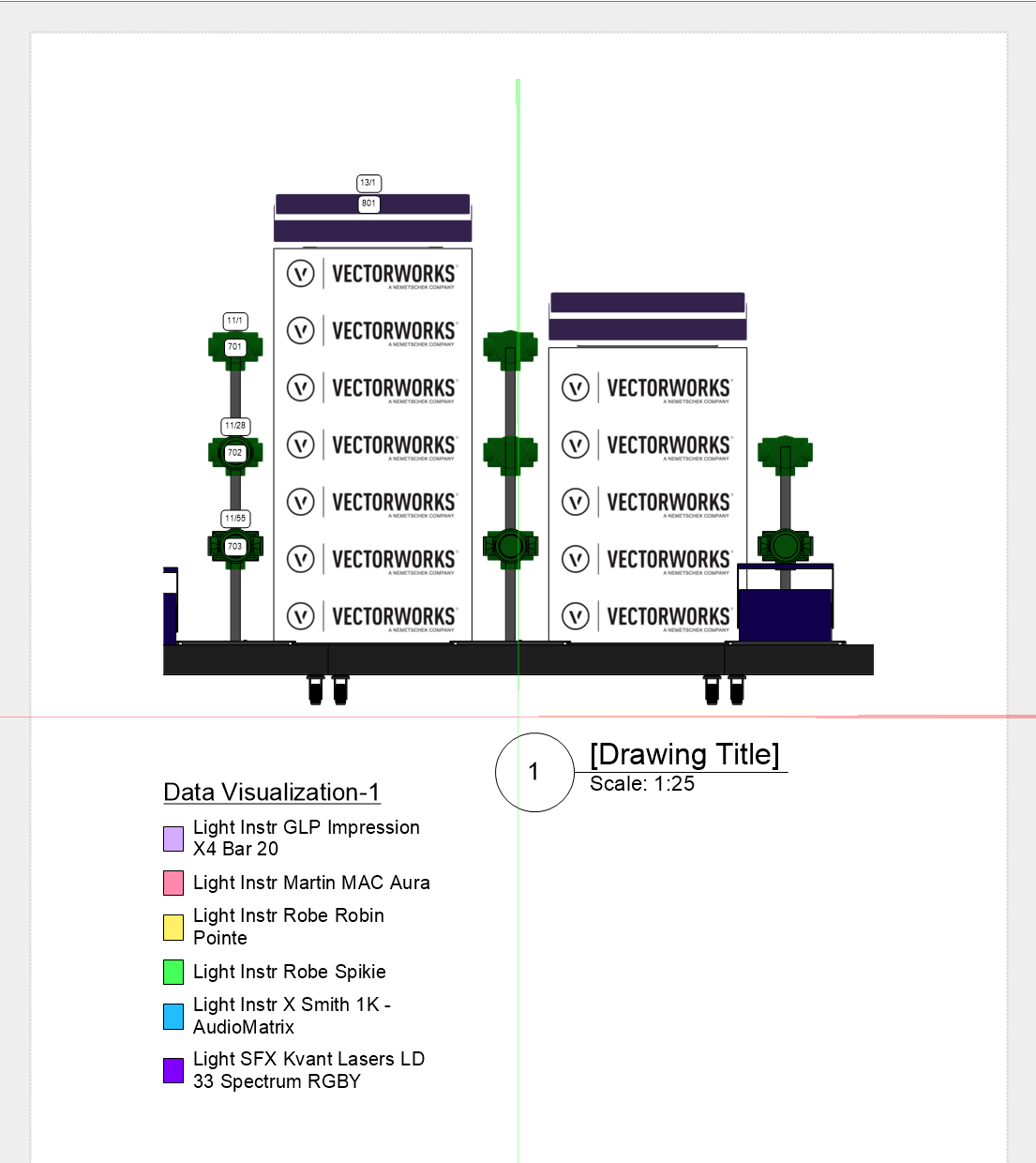
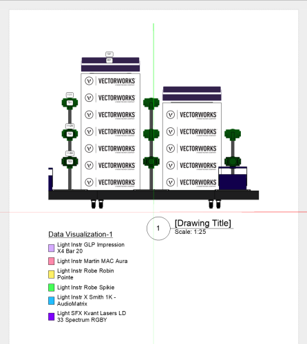
This is also an option. Viewport from front view with Background Render as Shaded to be able to use Data Visualization and Hidden Line as Foreground Render to bring lines to objects. Data Tags to make ID and address visible.
-
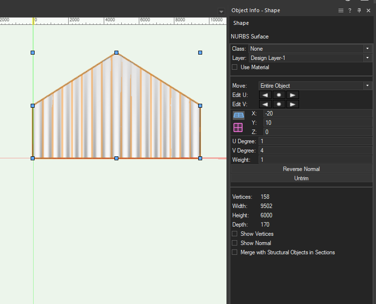
I presume that you want curtain at the end of tent and tent has straight triangular shape at the roof rigde. Way of doing this is to draw curtain with Soft Goods tool as wide as tent end is. Go to front view, use Convert to Group command(CTRL-K). Now you should have Nurbs Surface. Now you can use Split Tool to cut curtain along tent roof. You have to use Split twice to get both sides. Now you should have Nurbs Surface that has wavy form of Soft Good tool and geometry from tent end. If your shape is more complex then Marks video will guide you to achieve that.
-
Speaker Array - Rigging Frames & Pull-Back Bar
aheininen replied to Mark Aceto's topic in Entertainment
Are your new tools going to be part of Vectorworks stock tools in the future? -
Truss and Hanging Position: Missing OIP fields in worksheets?
aheininen replied to livespace josha's topic in Entertainment
My 2 cents, roll should be from the center of truss not from insertion point. Sometimes when inserting trusses, one piece turns somehow to wrong orientation on truss line. To correct this you can not just input correct roll angle because that "throws" that piece out of that truss line. To correct wrong roll you have to fight system to snap to correct roll. -
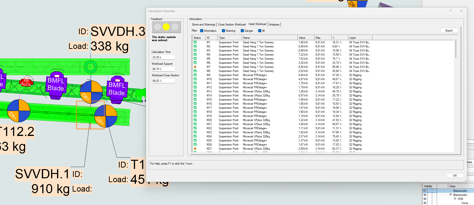
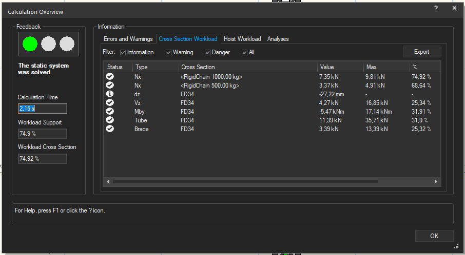
Hi, can I get colors back to status column in Calculation Overview? I thought that colors in status symbols were supposed to be easy to spot different levels of information. Now all OK and information level are equal and similar icons and not that easy to see on quick glance. At least warning is still different colored icon (yellow triangle with exclamation mark, not on this picture).
-
How to use label legend in one viewport not the other?
aheininen replied to hollyyjackson's topic in Entertainment
On possibility is to use Data-Tags in viewport to show information that you want to show in each. With different Data-Tag between viewports you can see data that is defined in different Data-Tags. I have Data-Tag that is similar visually and in data to my normal Label Legend. With that Data-Tag I can easily visualize ID and Addr even in oddly angled front views. On normal Top/Plan viewport I use just Label Legend because it is usually fastest way to show that data. Data-Tag is IMO easier to move if viewport is crowded, one click to move all fields compared to LL where you have to move all fields separately. -
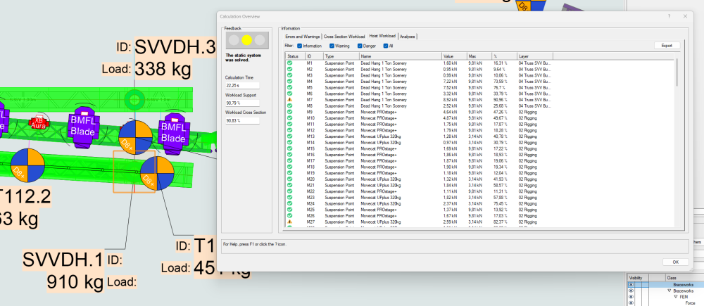
How from Calculation Overview I easily know with out double clicking row what is M7 in my drawing now that I have done Reset Braceworks ID:s? I can't even add columns to show Notes field from Hoist to know what M(Number) is what Hoist. If I could see Notes field I would know at instant what hoist is in question. Not to mention that ID could be ID that I have given to hoist and not the ID program likes to give to hoist. And if I happen to be in some 3D view double clicking the row takes view to some odd place that usually does not even show that hoist on clicked row. Maybe clicking row could change view also to Top/Plan to this function to work better?
-
But could Braceworks ID be separate from Hoist ID field? I think plenty on users use that as ID field to label hoist in plans. As Stefan said, now when you develop your best identification system to design it is all gone when you "Reset Braceworks IDs". You can also use Notes field to ID your hoists but that is not most intuitive way when you have Hoist ID field available. Lighting Devices don't use ex. Unit Number field for Braceworks ID. If you set Unit Number it is Unit Number even if you reset BW IDs. I recall some earlier thread in forums where there was discussion that BW ID could be changed to use some invisible UID in hoist. Has this been considered? In my honest opinion Hoist ID and Braceworks ID should be different data.