Search the Community
Showing results for tags 'export'.
-
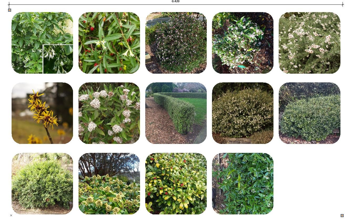
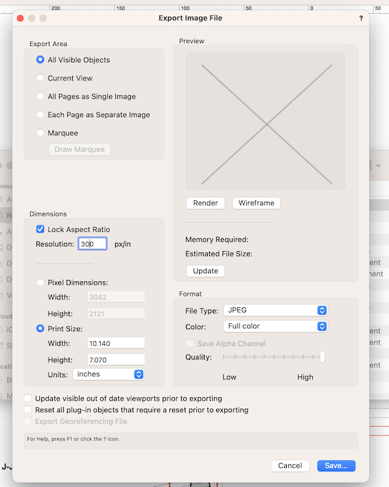
To get my .pdf file size down I’ve always set out my images for a given sheet and then exported as a single image, then adjust size externally & reimport – as in this example using a plant palette. But how can I automate this more? I’d like to hit a button and export everything within the coordinate space of the two highlit locus points (in encl. image) (ie using the export as image function). I almost always export .jpg, 300dpi (but sometimes I adjust that), at maximum quality setting. I’m not a script writer but is this something that already exists, or could someone here write such a thing? I always get width dimension of my sheetspace objects before entering dialog. I don’t use loci for anything else in sheetspace. Mouse: File > Export > Image file; Export Image File dialog {Alt f x i} - Export area, defaults to random setting. { m } - Dimensions, remembers its setting. {TAB is only access} - Quality, remembers its setting. {TAB is only access} - Format, remembers its settings. {TAB is only access} - Print size, height & width always some random number. Units defaults to inches, so always have to reset to cm ). {TAB is only access} Then press Draw Marquee Draw marquee in sheetspace Dialog returns with Save and one navigates to path and saves it A lot of steps – 13 or so, some of it forcing mousing, and I do it at least twice a day. A button would be amazing, and save a lot of time and fiddling. My musing - ignore for now A script would probably start with checking that locus points existed in current sheet. So can a script read/parse locus point positions as part of a process? Or do they need to be in a record? Or will a name suffice?
-
I'm trying to export a selection of sheet layers to DWG. I've tried this via 'publish' and 'export'. To test the export, I've dragged the DWG into a blank file and I get this grid all over the drawing. I've tried messing with the settings but with no success. Can anyone help? Thank you.

-
Hi, I have been having trouble getting sheet layers to export as shown in the Vectorworks Software. When Exporting as a PDF the fonts seem to be patchy and in both a JPEG and PDF export the drawings seem to be grey looking. This is what the sheet layer looks like on the software: This is what it looks like as a PDF: This is what it looks like as a JPEG: I have made sure that my DPI is 300 and every export is at the maximum quality. Any help would be appriciated
-
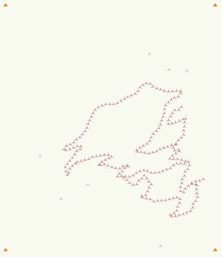
I have a set of 244 2D [encl. with bound box loci selected to highlight area], (3D is an option I have as well) locus points and a single closed 2D polygon - in its own class and the locus points likewise in their own class. I want to export the points as a cloud of x,y points in this format: 1378385.1650620073,4938850.9892900344 [and with a ,0 for the 3D version - I don't need heights for this] What I want to achieve is a txt / csv / tsv type file, with a list of x,y,z I can then hand build into a GPX file to import to my gps. The points are currently simply 2D (or 3D) loci, and do not have record info so I can’t export to .shp (which is a bit silly of Nemet as any GIS will import very simple files). Neither 2D or 3D loci export to .dxf. This is a lot of kerfuffle for what is one of the worlds most basic and essential spatial data formats. I tried exporting as script file and I got the loci but 258 instead of the 228 that I have in my drawing I've converted my field edge and bounding box to 3D loci so I can verify against georef space. If it matters the file is georeferenced to EPSG2193 (a standard New Zealand datum).
-
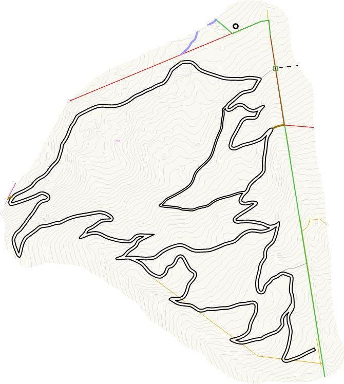
Before I reinvent the wheel I'm asking here to see if anyone else has got a workflows for exporting .gpx file. I want to use one from a drawing in my Garmin Etrex 32x to set out a walking path. I know there's a workflow to get one out of QGIS but want to know if VW offers a more straight-forward route for my very windy path - about 1200m: image encl. for anyone interested. openstreetmaps have kindly written up the gpx format, and I can build from scratch from a points export but hopefully there's a smoother way.
-
Hello everybody! im trying to get my datatags for my spaceobjects exported into ifc. As far as i know, the IfcEntity here should be IfcAnnotation. I tried mapping it with the datamanger but cant get the tags exported into Ifc. simple text- or dimensionobjects didnt work either. does somebody know if and how its possible to get them exported ? thanks in advance! regards gsp_nowhere
-
 @Eric Gilbey, PLA @Vladislav Stanev @Tony Kostreski We need better control of our DWG export process from VW. In order to coordinate with almost everyone, we still rely on this process and unfortunately, it is an extremely time consuming process...both in Vectorworks and in AutoCAD to deliver a product that is acceptable. I have voiced several of these concerns in various topics/threads/forums before to no avail, so I am trying one last time! One thing in particular I am noticing now is that Hardscape objects become AutoCAD blocks, regardless of the export settings! This is BAD...very BAD. We need the ability to have clean, simple, traditional AutoCAD files with minimal time spent exploding and cleaning them up. Block objects are relatively useless to a consultant, who will completely disregard files we send if they have to spend too much time on them. Next. Even if I go through the process of EXPLODING the hardscape blocks in AutoCAD myself, the result is NINE (9) overlapping coincident objects! WHAT?!? This is horrendous! Even if I go through the OVERKILL command in AutoCAD to try and eliminate coincident objects, it will only delete (5) of the (9) overlapping polylines, leaving me with (4) redundant shapes and a pissed of consultant! I am sure these are the result of the SLAB sub-components being exported, but we need a way to ignore that and get simple 2D linework to export. One of the BIG challenges we now face with VW is what is the BEST hybrid geometry to use for exterior hardscape/paving/slabs? For a long time we used floors because they were simple and didn't have any of the issues mentioned above. Hardscapes, although they have made simple strides recently, have always had problems. Additionally they allowed us to manipulate 3D textures on the surface independently, very easily. Obviously, for complex grading scenarios they were ineffective, but for simple "flat world" 3D models, they were perfect...until 2019. VW destroyed FLOORS and their simplicity in 2019 and we have been forced to using Hardscapes. The problem, in addition to the aforementioned export problems, are Hardscape Styles SUCK - They don't act like other styles where, when edited from a central location (the Resource Manager), they should update globally...they don't. CANNOT manipulate 3D texture direction - Think of pavers. If you want to have a varied direction for paver patterns, perhaps following the longest edge or two linear patterns running perpindicular to one another, you cannot do it. It is impossible! 3D Textures sometimes just don't work. Matching properties to ones that do, recreating, editing styles or slab styles all fail to make textures even appear (wireframe) on hardscapes on occassion. I haven't been able to really dive into this specific problem because it happens at inopportune times Slab Styles will automatically switch or break from time to time and have to be manually reset on each object or use the match properties...this should be easily controlled By Style. I know you are making strides in the Hardscape object in VW2020 and I haven't had the chance to really test them yet, but I'm fairly certain that none of these issues have been resolved yet! THIS IS HUGE FOR US! Please find a way to fix these issues ASAP! We need a "Hardscape" tool and workflow that doesn't compromise our workflow...in any way, let alone in 4 or 5 different ways.
- 3 replies
-
- 5
-

-
- hardscapes
- dwg
- (and 1 more)
-

export Naming Schemes for exported files
bcd posted a question in Wishlist - Feature and Content Requests
Currently - in the File Export Options there is an option to set a naming scheme per PDF pages - I'd like a similar option to available for the PDF file itself. Also - it would be good to have the option to pre-define a number of such file-naming schemes so that a drawing can be exported to eg. Vendor, Client, Shop etc with appropriately titled filenames. -
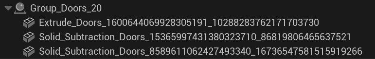
 This is previously discussed in this other thread, however that one is more about the general workflow issues whereas I am looking to highlight the specific 'too many children' issue here when exporting a Vectorworks file to Unreal Datasmith. I am using VW 2023 SP3. When I have a group in Vectorworks, the group is given it's own parent for the group. That makes sense, but then each of the meshes as apart of the group have their own actor & child mesh-actor. This middle actor can be removed. It serves no purpose. For reference, here is this group. It's 2 solid subtractions & 1 extrude. This will currently export as this: <Actor name="Group_Doors_20" label="Group_Doors_20"> <Transform tx="0.0" ty="0.0" tz="0.0" sx="1.0" sy="1.0" sz="1.0" qx="0.0" qy="0.0" qz="0.0" qw="1.0" qhex="0000000000000000000000000000803F"/> <tag value="Empty Actor" /> <children visible="true"> <Actor name="Solid_Subtraction_Doors_73" label="Solid_Subtraction_Doors_73"> <Transform tx="0.0" ty="0.0" tz="0.0" sx="1.0" sy="1.0" sz="1.0" qx="0.0" qy="0.0" qz="0.0" qw="1.0" qhex="0000000000000000000000000000803F"/> <tag value="Empty Actor" /> <children visible="true"> <ActorMesh name="Instance8589611062427493340_16736547581515919266" label="Solid_Subtraction_Doors_8589611062427493340_16736547581515919266"> <mesh name="Mesh16896199164350926892_7180970239964908936Sub0"/> <Transform tx="677.549194" ty="-998.677795" tz="101.535332" sx="1.0" sy="1.0" sz="1.0" qx="-0.000104" qy="0.000321" qz="-0.951752" qw="0.306866" qhex="7B5CD9B89F89A8390DA673BF991D9D3E"/> <tag value="Mesh Actor" /> </ActorMesh> </children> </Actor> <Actor name="Solid_Subtraction_Doors_58" label="Solid_Subtraction_Doors_58"> <Transform tx="0.0" ty="0.0" tz="0.0" sx="1.0" sy="1.0" sz="1.0" qx="0.0" qy="0.0" qz="0.0" qw="1.0" qhex="0000000000000000000000000000803F"/> <tag value="Empty Actor" /> <children visible="true"> <ActorMesh name="Instance15365997431380323710_86819806465637521" label="Solid_Subtraction_Doors_15365997431380323710_86819806465637521"> <mesh name="Mesh279954500711682462_8339932488154455650Sub0"/> <Transform tx="677.549194" ty="-998.677856" tz="101.614708" sx="1.0" sy="1.0" sz="1.0" qx="-0.000104" qy="0.000321" qz="-0.951752" qw="0.306866" qhex="7B5CD9B89F89A8390DA673BF991D9D3E"/> <tag value="Mesh Actor" /> </ActorMesh> </children> </Actor> <Actor name="Extrude_Doors_21" label="Extrude_Doors_21"> <Transform tx="0.0" ty="0.0" tz="0.0" sx="1.0" sy="1.0" sz="1.0" qx="0.0" qy="0.0" qz="0.0" qw="1.0" qhex="0000000000000000000000000000803F"/> <tag value="Empty Actor" /> <children visible="true"> <ActorMesh name="Instance1600644069928305191_10288283762171703730" label="Extrude_Doors_1600644069928305191_10288283762171703730"> <mesh name="Mesh10132752585299418352_16003714575914235506Sub0"/> <Transform tx="677.549194" ty="-998.677795" tz="101.455956" sx="1.0" sy="1.0" sz="1.0" qx="-0.217061" qy="0.673218" qz="-0.672763" qw="0.216914" qhex="24455EBE02582C3F383A2CBFB91E5E3E"/> <tag value="Mesh Actor" /> </ActorMesh> </children> </Actor> </children> </Actor> But should instead export as: <Actor name="Group_Doors_20" label="Group_Doors_20"> <Transform tx="0.0" ty="0.0" tz="0.0" sx="1.0" sy="1.0" sz="1.0" qx="0.0" qy="0.0" qz="0.0" qw="1.0" qhex="0000000000000000000000000000803F"/> <tag value="Empty Actor" /> <children visible="true"> <ActorMesh name="Instance8589611062427493340_16736547581515919266" label="Solid_Subtraction_Doors_8589611062427493340_16736547581515919266"> <mesh name="Mesh16896199164350926892_7180970239964908936Sub0"/> <Transform tx="677.549194" ty="-998.677795" tz="101.535332" sx="1.0" sy="1.0" sz="1.0" qx="-0.000104" qy="0.000321" qz="-0.951752" qw="0.306866" qhex="7B5CD9B89F89A8390DA673BF991D9D3E"/> <tag value="Mesh Actor" /> </ActorMesh> <ActorMesh name="Instance15365997431380323710_86819806465637521" label="Solid_Subtraction_Doors_15365997431380323710_86819806465637521"> <mesh name="Mesh279954500711682462_8339932488154455650Sub0"/> <Transform tx="677.549194" ty="-998.677856" tz="101.614708" sx="1.0" sy="1.0" sz="1.0" qx="-0.000104" qy="0.000321" qz="-0.951752" qw="0.306866" qhex="7B5CD9B89F89A8390DA673BF991D9D3E"/> <tag value="Mesh Actor" /> </ActorMesh> <ActorMesh name="Instance1600644069928305191_10288283762171703730" label="Extrude_Doors_1600644069928305191_10288283762171703730"> <mesh name="Mesh10132752585299418352_16003714575914235506Sub0"/> <Transform tx="677.549194" ty="-998.677795" tz="101.455956" sx="1.0" sy="1.0" sz="1.0" qx="-0.217061" qy="0.673218" qz="-0.672763" qw="0.216914" qhex="24455EBE02582C3F383A2CBFB91E5E3E"/> <tag value="Mesh Actor" /> </ActorMesh> </children> Hopefully it is clear how this is far more useable & clear.
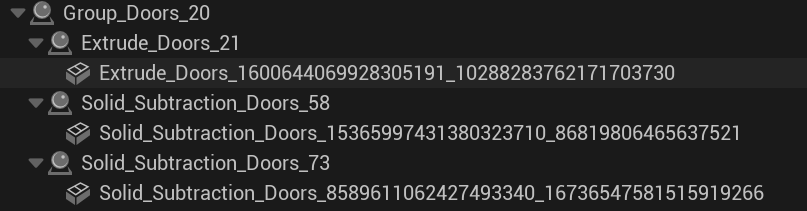
-
I have a need for an .xyz points file for manipulation in another software. While VW allows export of early dxf formats, there's no option for export of 3D points aka vertices. Currently I'm using https://www.guthcad.com/dxf2xyz.htm but it adds quite a few steps (and ime requires a very early-format .dxf), and it'd save time to avoid it. .xyz points file format looks like this: 81525.081217,21129.437724,490.905487 - for X Y & Z coordinates
-
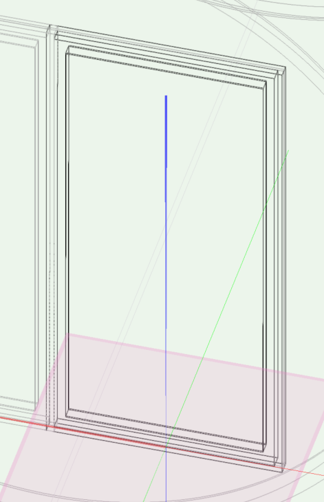
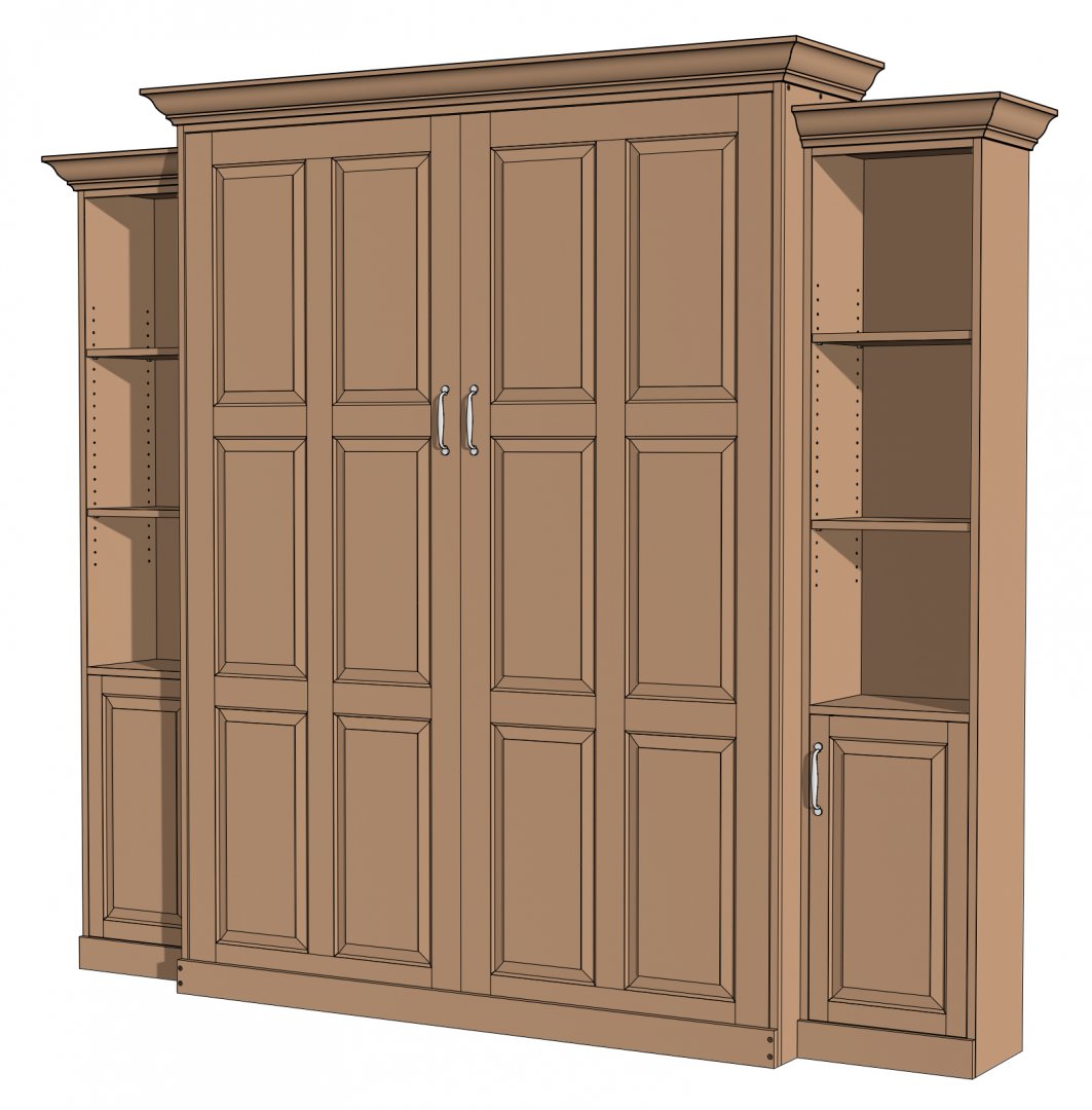
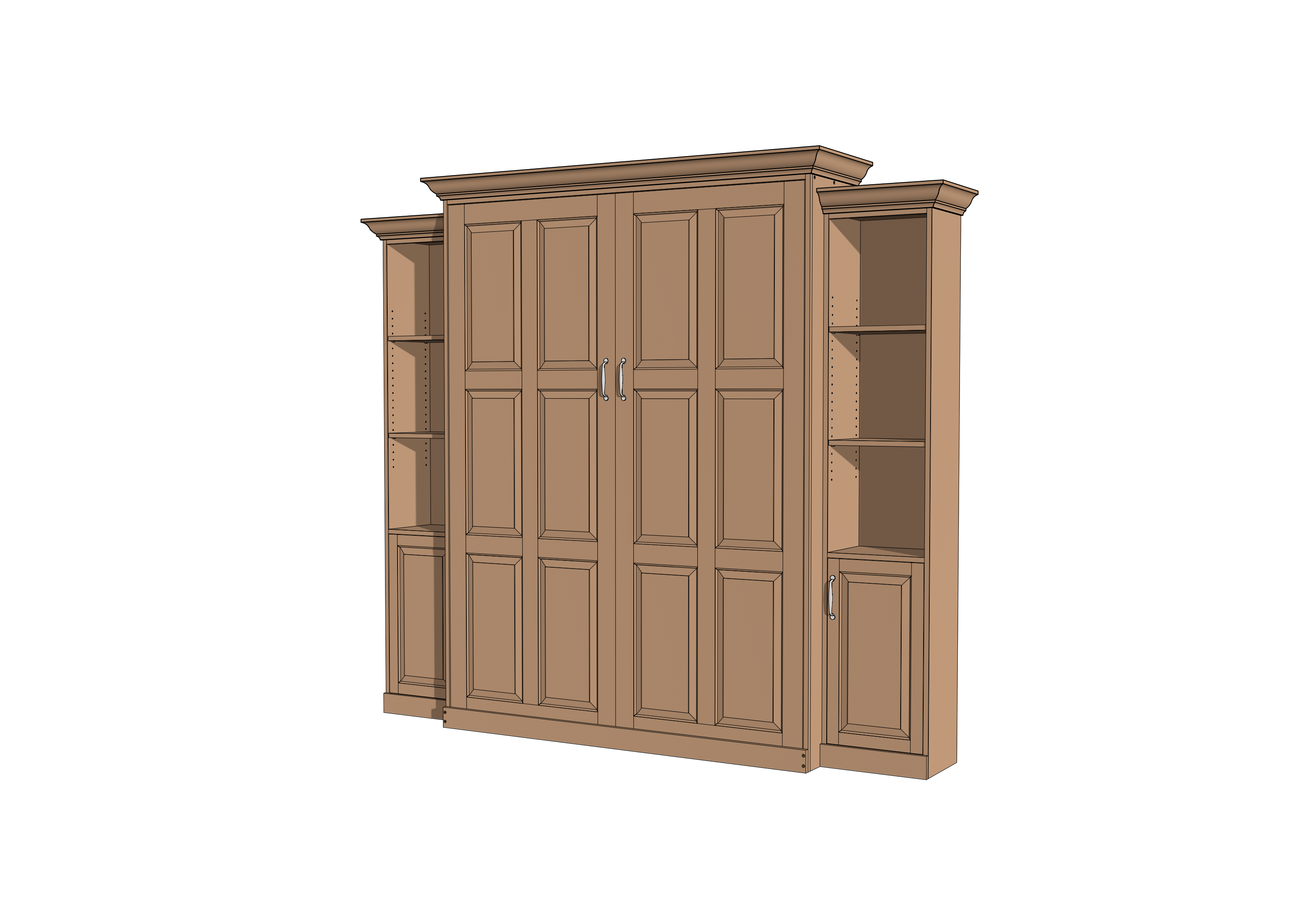
What I see in my Vectorworks file is what I want to see when I export the image, but it is not. Is there a file format or setting that will give me the same results as what I see in Vectorworks? This screen shot is accurate. Oddly it can reproduce the colors extremely close (if not exactly the same), but Vectorworks cannot. This is a JPG export: This is a PNG export: This is a PDF export: Murphy Bed Queen Complex.pdf

-
 So I went to export the design layers & sheet layers (to dwg) from a .vwx, and selected to export layers as separate files. My vwx file is 445Mb, and the file has no references. I'm running vw2018 landmark on win 64. I did the design and sheet export as separate processes as have had problems with this before. Design space export was pretty much what I expected, one .dwg file per layer, some .pat & .ctb files, and a stack of bitmaps, all .png which is kind of annoying, but overall pretty much what I expected and about 250Mb. Exporting the sheets ... I killed process after half an hour as it had got 40% through and filled a folder with 7.6Gb of of mostly.png files {oi seemed to be working thru the sheets as it had created eight .dwg's}. All images are duplicated multiple times. Most bizzarely my .wvx file grew to 660Mb, and stayed that size after save. I haven't been able to find out what the extra nearly 200Mb is and fortunately I had a backup. I suppose I'm writing this as wa rning to others of what looks like a serious bug.
 -
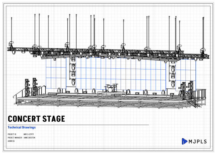
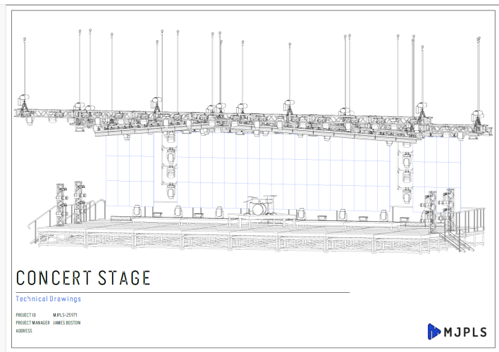
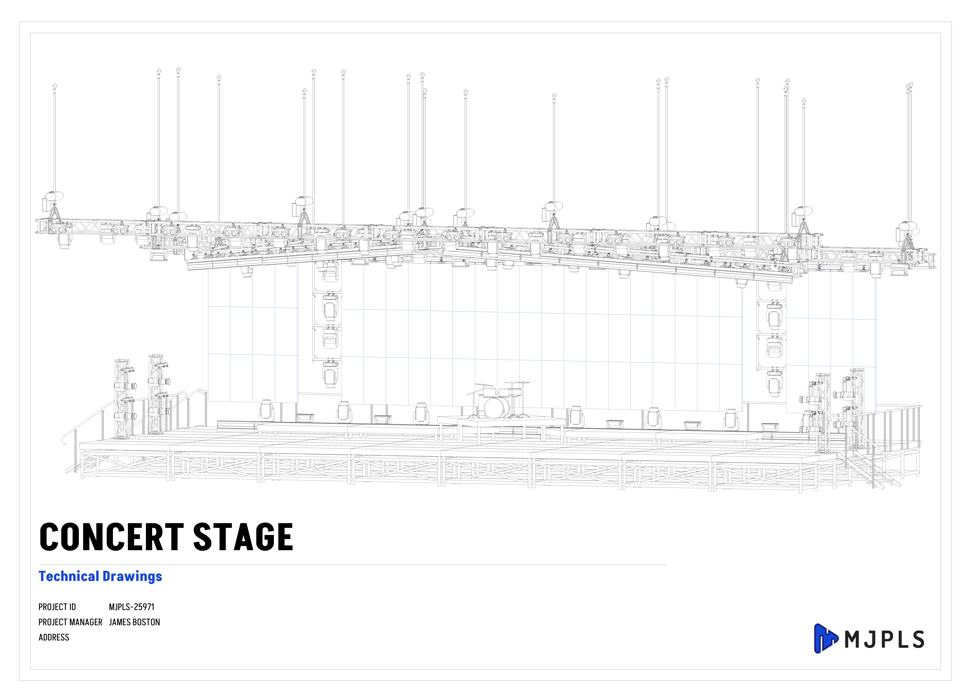
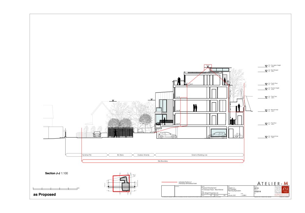
Currently trying to export images of my line drawings for a Design & Access Statement. Using Apple Pages so exporting as JPG/PNG is my best bet for cropping effectively and getting file sizes down. However, I think I have messed about with the settings previously and my image file exports are always blurry or contain thick lines compared to PDF. Is there something wrong with my settings? Thanks. 2210 - Planning Materials 3.pdf
-
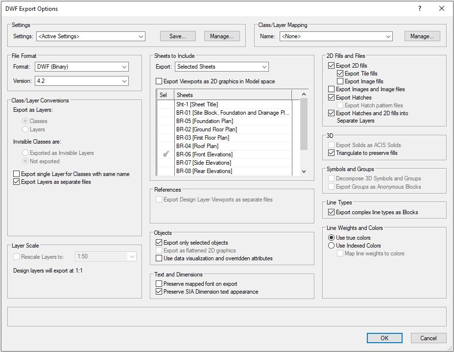
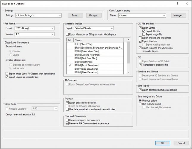
 VW>AutoCAD question: --I want to export a VW drawing such that when I open it in CAD the following is true: all the parts/components/lines/groups/etc of a lighting instrument are on layer '0'. The actual symbol instance in the drawing is on layer 'Lighting-units'. --In VW, I've edited the symbol so all parts of the light are class '0'. When I insert a bunch of examples of that symbol in the drawing on class 'Lighting-units', things behave as expected: if I turn off either class, all the symbols disappear. --When I export to CAD, and try the same thing, freezing the '0' layer doesn't make the symbols disappear, but freezing 'Lighting-units' does make them disappear (as expected.) --In CAD, groups DO behave as expected here, i.e: the layer '0' still turns things invisible when frozen (the inner parts of the group are '0') as does 'Lighting-units' layer (the group as a whole is in this layer). Running VW2021 and AutoCAD 2023 all on PC. Here are my export settings if that's useful:
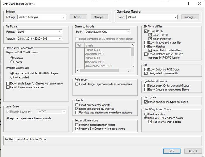
-
Anyone had any success with KML export from Vectorworks? Almost got a lovely 3D model into Google Earth Pro, but it comes in about 100m off in terms of location. I think the geo-referencing in Vectorworks is ok... any tips or tricks to get it to work? Note we've already looked at this on Vectorworks University - seems now I don't even have to put the lat/long in, as it's picked up from the document geo-referencing, so I have no control really over location other than this, and my file settings are correct...
- 1 reply
-
- 1
-
-
- georeference
- kml
- (and 3 more)
-
Hi all ! I am looking for the best solution to export my vectorworks project to blender for texturing and rendering. That is to say the best compatibility, the best format, the best way to have a blender project organized from vectorworks. Thank you all
-
is it possible to export saved views to another file? I don't see any way of doing this but would be very very useful if there is a workflow or script that enables this. I'm using VW 2018 on PC.
-
It would be great to get a little status bar when doing an export or publish process so you can get a sense of what VW is doing (though you do get a nice complete dialog at the end)... while you wait, maybe take a quick nap, grab a cup of coffee, whatever. There's no indication that something is happening other than: the program is locked up. Which leads to the question: is Vectorworks doing something or did it crash? There's a pattern there for heavier processing tasks (I.e., rendering / updating viewports 😮). A global, functional status bar would be ideal.
-
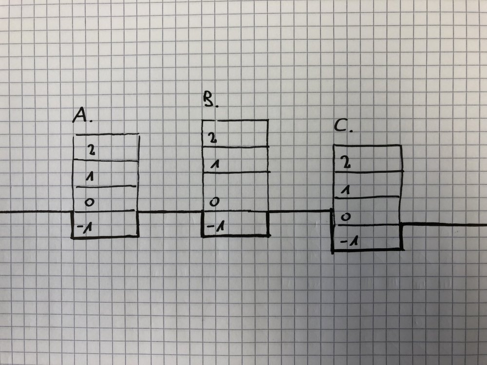
Please, find bellow a drawing showing my 3 buildings to illustrate my post. 1. What I observed - It is not possible to have 2 stories at the same level (for instance A0 and B0 on the same level) - It is really annoying (and I'm trying to stay polite here) to set these stories one bye one when you have 12 buildings, 50 stories, 70 layers. In one window they are listed by name, in another by level; I had to print my layers manager and highlight my stories like in the '80s to see what's happening. After approximately 801'153 clicks I got what I wanted. 2. My questions - How to set properly a file and their stories with multiple buildings in order to export it to IFC ? - Is it really mandatory to assign stories in order to export an IFC ?
-
Hi, I use VW but two of my colleagues will be modelling in Sketchup. Are there any tips on workflow? Ie guidelines on how to best export and import? In the past I have found models I've imported in VW from SU to be very fragmented and need a lot of cleaning up. The person I'm working for will model in Sketchup and then ask me to import the model into VW to produce working drawings He'll also want to make changes to the model (in VW) and then also texture and light for rough renders. Then pass the model back into SU Is this possible? or better to just transfer it once from SU to VW. Any tips on how I can save hours remodelling / fixing up the model so it is editable in VW? much thanks, Helen
-
Hello people, I just edit because I found this way. import vs import os Vendor = 'ACME' Price = 123.45 Tax = 1.07 fileName = 'Classes.txt' def Example(): vs.GetFile(fileName) if not vs.DidCancel(): vs.Rewrite(Vendor, 0) #vs.WriteBin(Vendor) #vs.WriteMac(Vendor) #vs.WriteLnMAC(Vendor) #vs.Write(Vendor) vs.Close(fileName) Example() But, the next attributes get this message: "AttributeError: module 'vs' has no attribute 'WriteBin'. " -vs.Write -vs.WriteLnMac -vs.WriteBin -vs.WriteMac With write I don't get error, but also no result. -vs.Rewrite
-
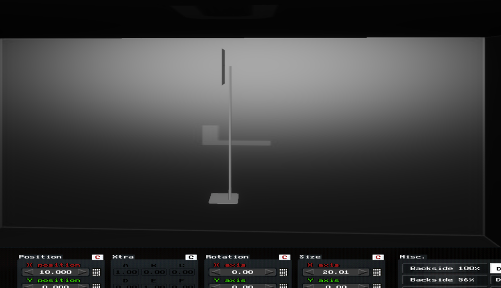
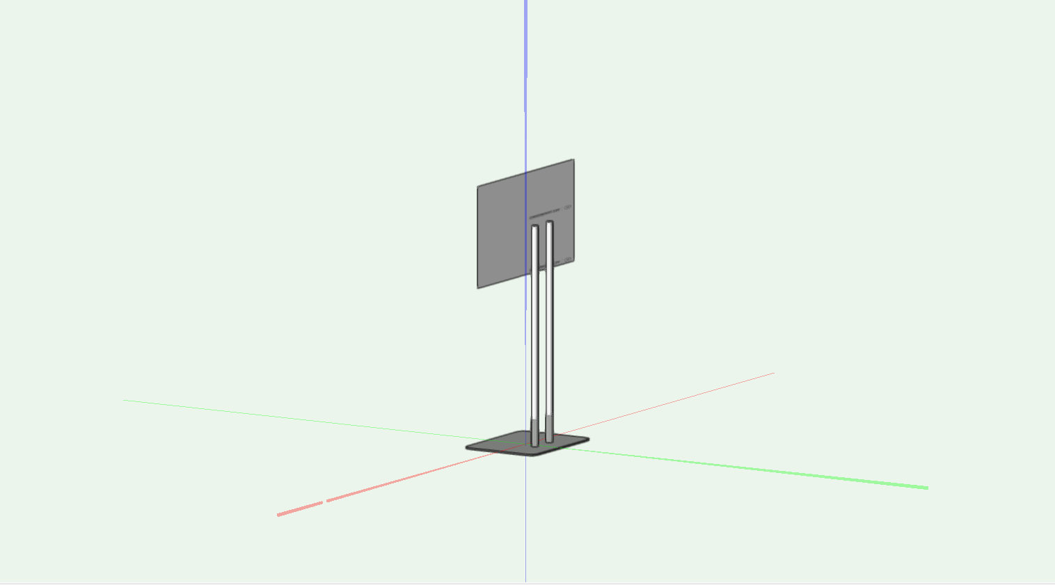
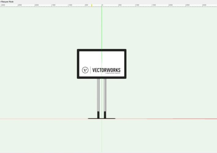
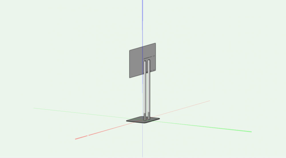
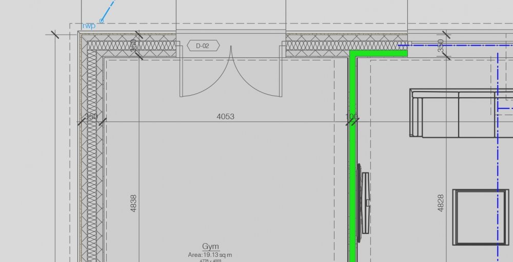
Good day! When trying to transfer a project from vectorworks 2022 to L8 using MVR, the geometry of some elements is transferred with errors. For example, a TV set made using TV Tool is transferred normally, but if you add a stand to it, then only the screen texture and stand are transferred from the TV, the TV itself is not visible in the document. But if we remove the stand, then the TV is exported normally, with the body and textures. If we try to import the MVR file back into VectorWorks, we will get the same result, only the TV screen will be visible. Unfortunately there will be no body. Please advise how to fix this problem.


-
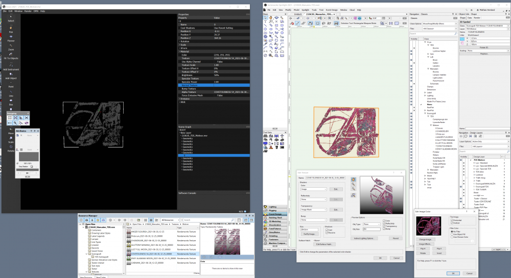
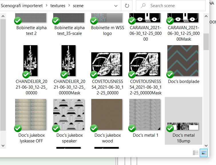
Hi I seem to run into a problem when exporting some set-elements from Spotlight, to Vision. My worksflow is to export to MVR, and then import the MVR to vision. But my textures seem to loose all color when exported to MVR. I use the alpha channel of the texture, as alpha channel in vision. Does any of you experience this behavior? Here are screenshots of my settings. I found that the textures in the vision texture folder is Black and white as well, like both are alpha textures. See the screenshot: Best from Mathias
-
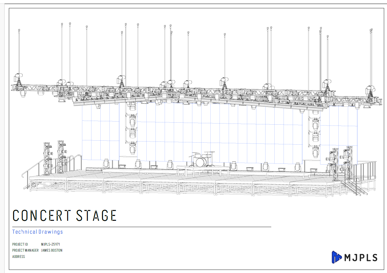
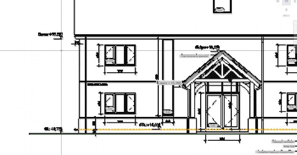
Hi all, I've been touching this somewhat now as some more people are asking for the digital files instead of PDF's and when i was trying the settings to see what fitted better i got the result shown below. For the Floor plan works wonders and looks properly as i wanted it to show. But for some reason the elevations are not showing properly, it looks like its creating a very low res image on the front of the file and obviously this is not the result i'm looking and it takes almost 15 to 20 mins. although the fine lines and high res drawing lines as the above are there but it duplicated all the drawing as a low res image for some reason. The settings i'm using are these for both of the above images. What am i doing wrong here ??
-
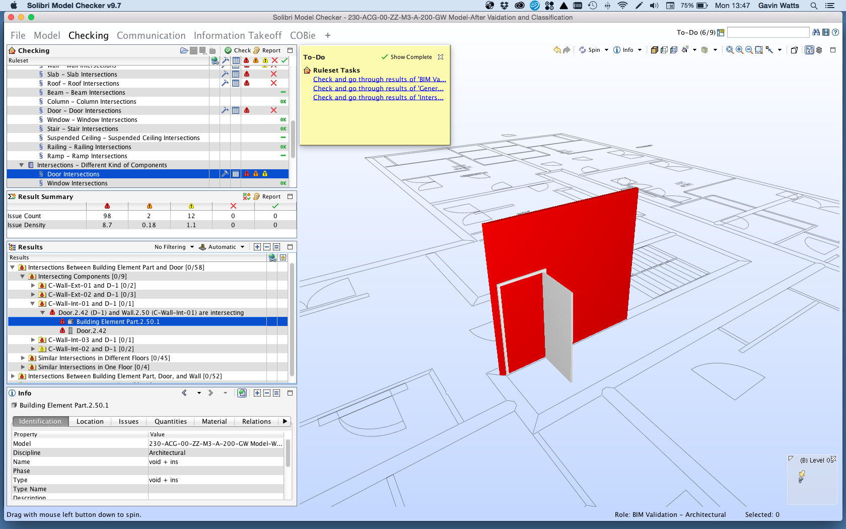
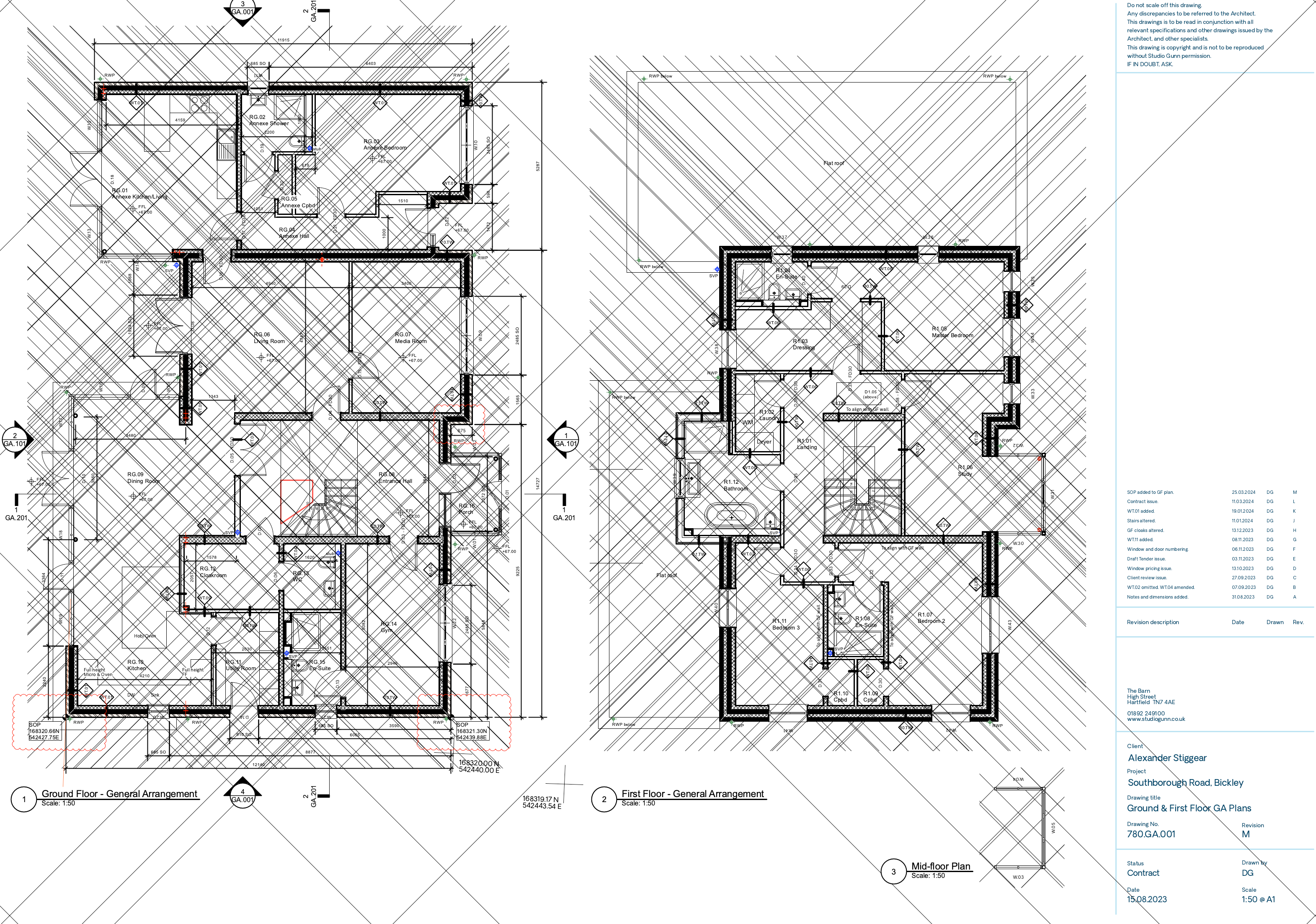
Hi, I am currently working towards PAS1192:2-2013 mandate and I am having some issues with the IFC import and the way we create windows. As we work on large housing schemes we work with window types, a method Vectorworks have previously advised to do it. So we create windows and then turn into symbols, so when placed within a wall they appear as a 'symbol in the wall'. However when exporting to IFC and either re-importing into VW to test or into Solibre Model Checker, the IFC format does not acknowledge the relationship between the wall and the window. I therefore tried exploding the symbol to test if it was this and when it is a 'window in wall' it views fine. I was wondering if anyone has had a similar issue and a work around. One way i was going to try was using symbol geometry in the window settings. therefore if you change the original source component then this will still change. However this will result in manual window changes to each window for height width etc. I have attached a solider model checker screenshot showing the if import result of a door in a wall as a 'symbol in a wall'. This also applies to doors. Thank you. Gavin