Stéphane
-
Posts
145 -
Joined
-
Last visited
1 Follower

-
Hi, I have the same issue, but I couldn't solve it. My file structure : - Class for slab objects - Class for wall objects - Class for each component used in slabs and walls, sometimes I use the same class, for instance "Concrete". They are set so visible. Now, if I set the class "Concrete" to invisible, it removes the unwanted hatch of the slab objects in the exported DWG, but it also removes it from the walls. I want the components hatches removed from the slab objects but not from the wall objects. When I export the layout to PDF I don't have this issue : Slab objects don't generate their components hatches, because they are not cut. I would like my DWG to be exactly like my PDF.
-

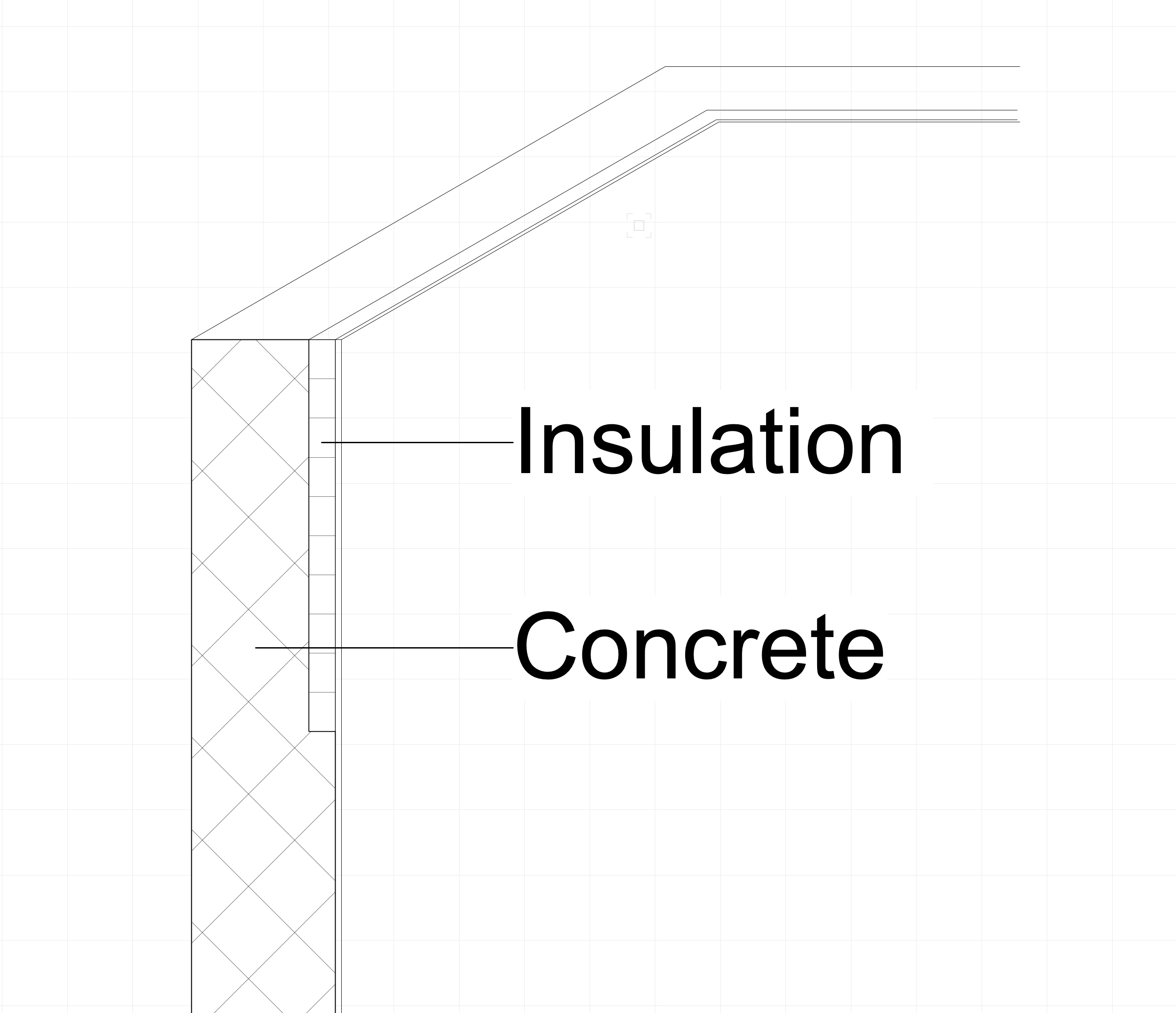
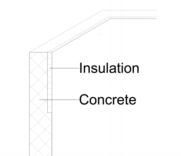
How to draw a wall with "insulation lost in formwork"
Stéphane replied to Stéphane's topic in General Discussion
@Tom W. Pretty nice solution, thank you ! I have tested it and it looks much more efficient than these wall features. @cberg Thank you for your honest answer. "If it sounds painful. It is. And we've all been there. " Somehow, that comforts me, thank you. I think I'm going to do a mix of your solutions : I will only split the insulation part as Tom W. suggested it and class it amongst everything that is under the slab and deactivate it in plan. Instead of duplicating the openings, maybe I could just split the wall above them and offset the bottom accordingly.... Need to test this. -
Hello, I would be glad to get your precious hints on my issue. Since one drawing is better than one thousand words, please find my issue below 🙂. How would you draw such a wall ? I tried walls features but I have 2 problems with them : - difficult in the angles - somehow refuse to show the hatch I want, always shows the extrusion filling attributes in a hidden line section viewport (so it is always a solid color with no contour
-
@Tom Klaber You described exactly what I experience when I do OpenGL renderings in VW2021 SP5. What I observed : - Memory pressure stacks after each renders. When memory pressure reaches 34 GB, VW crashes. - Save, quit and restart VW release the memory. - My routine to prevent a crash when I do OpenGL renders : 1. No more than 5 renders. 2. Save, quit and restart. 3. Back to point 1. - I lost a keyboard last Friday because I did 7 renders before saving and had to redo everything 🙂
-
One or more operations were aborted due to lack of memory
Stéphane replied to Christiaan's topic in Architecture
Still an issue in VW 2021. VW doesn't release memory after an openGL rendering. I have to save&restart after 10 pretty basic renderings. -
Thank you very much for this, @Pat Stanford. I will share here the conclusions for other VW CH_FR users (Potentially 2.2 mio users 🙂) 1) My door is a 'Door CW' not a 'Porte' 2) The fields in the OIP are actually translated from German. So you need to call them in German. 3) The IFC fields are always in English. 4) If you click on the little arrow in a cell and select "Database" and the PIO you want ("Door" or "Window" or whatever) you will find a list of all parameters you can use. So what I was looking for was : ='Door CW'.'BaseQuantities_Height'/10 (/10 because BaseQuantities are in mm but I work in cm) ='Door CW'.'BaseQuantities_Width'/10 ='Door CW'.'Türhöhe' ='Door CW'.'Türbreite' ='Window CW'.'BaseQuantities_Height'/10 ='Window CW'.'BaseQuantities_Width'/10 ='Window CW'.'Fensterhöhe' ='Window CW'.'Fensterbreite'
-
Hello there, Awesome explanations, @Pat Stanford, thank you for that. My VW is set in French and =(Door.Width) doesn't seem to work. I use a PIO which is called Porte. In the OIP there is a field called "Largeur de la porte" =(Porte.'Largeur de la porte') doesn't work neither. Questions : Does your trick work for each PIO ? How do you get the name of a PIO ? Is it the one written at the top of the OIP ? Is there an official English name hidden somewhere ?
-
@Matt Panzer Thank you for your feedback. I haven't updated to VW 2022 yet; Have you tested it in 2022 ?
-
Thank you @Matt Panzer to have a look into it : Test quantités.vwx
-
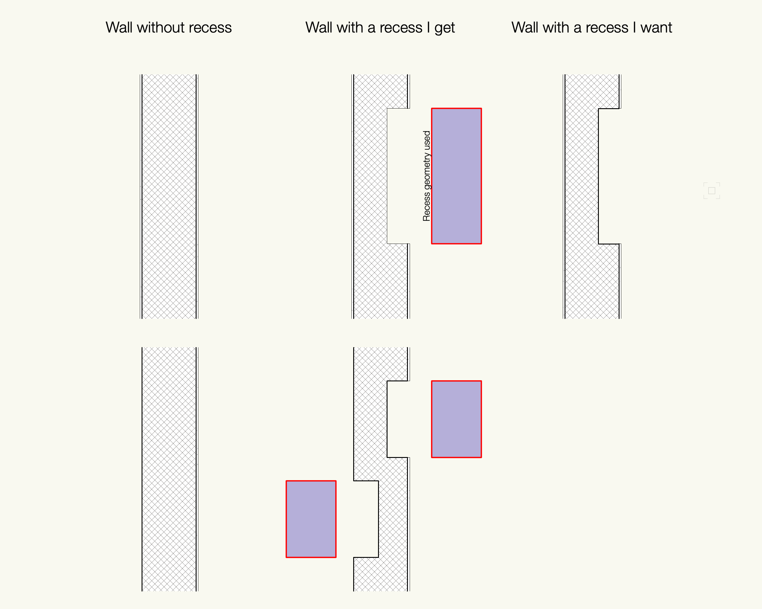
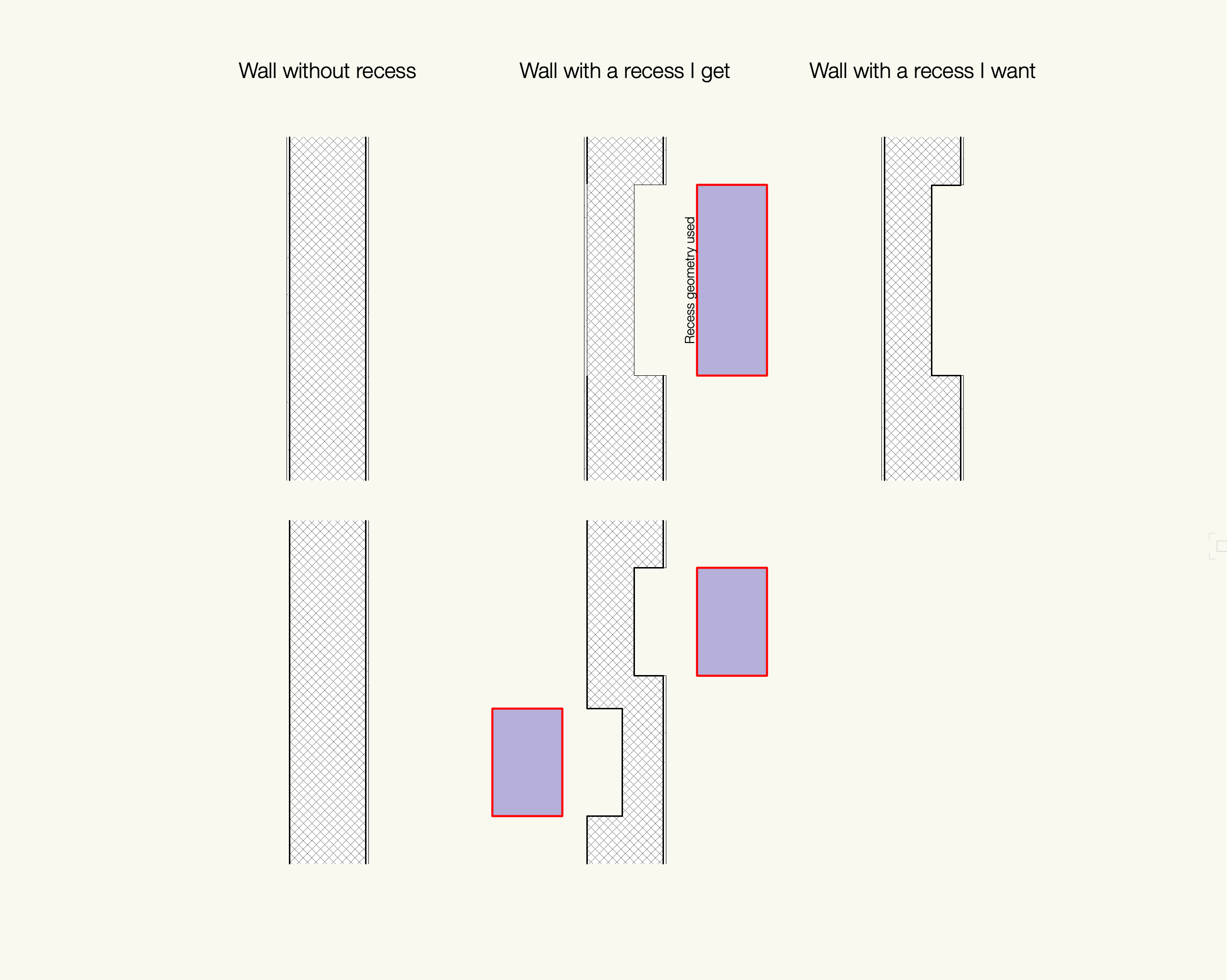
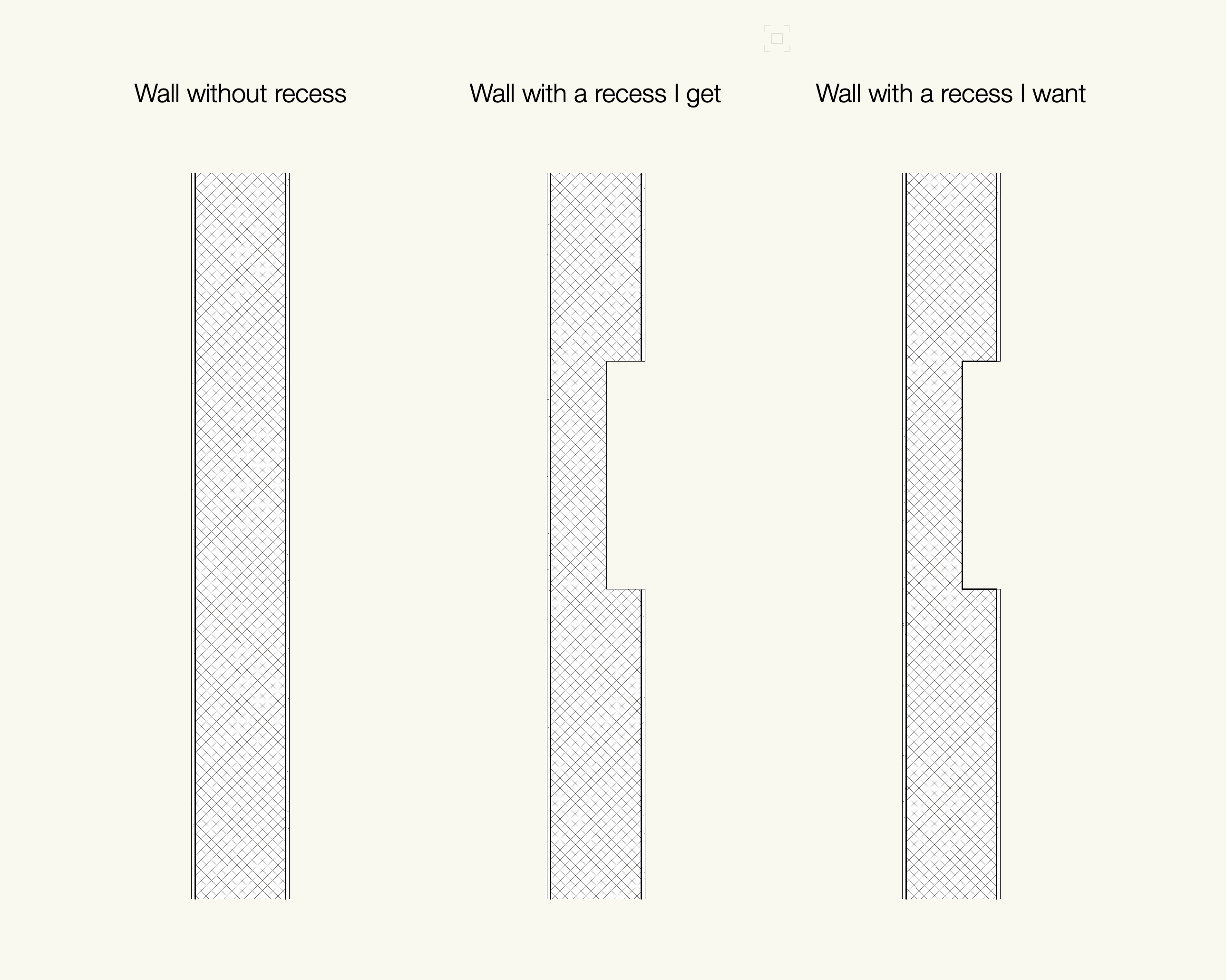
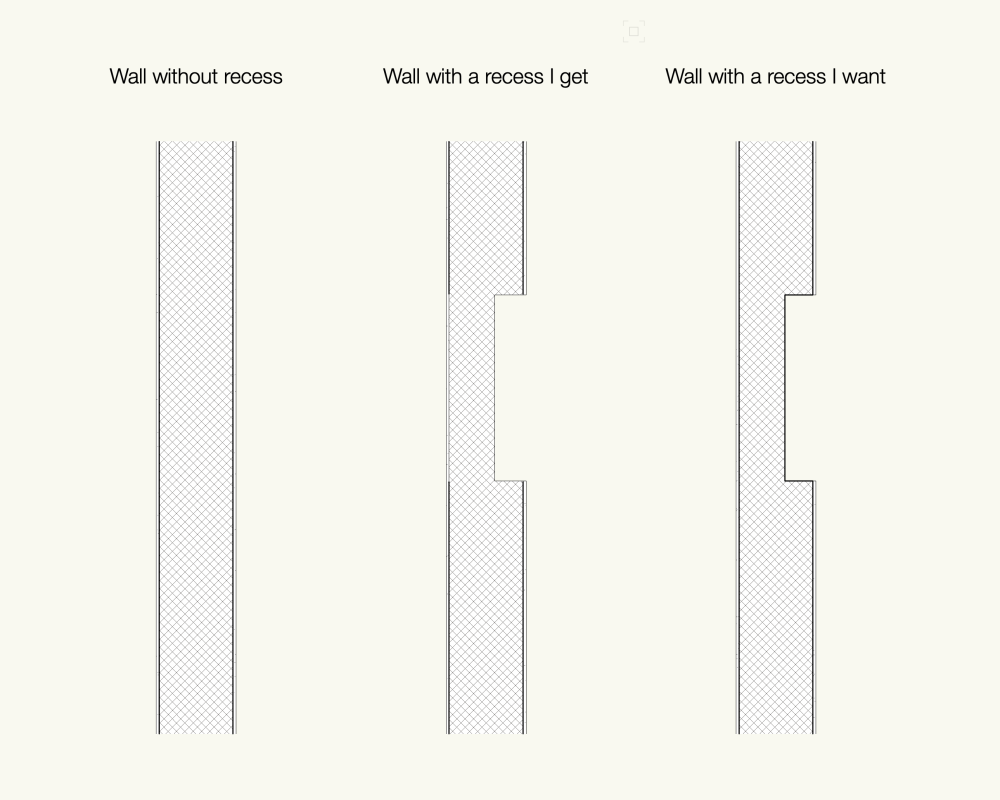
Progress has been made... I added a line to both side of each component in component settings. Still 3 thick lines missing in the recess.

-
That was my first guess, but no. First line is finishing-concrete-finishing. Second line is concrete-finishing. No issue with this one. Weird, isn't it ? See below.

-
Hey, May I bump into this topic with a related issue ? I tried the feature technique with a multi components wall and my lines thickness get messed up. See below. Any hints ?
-
Angular and radial dimensions in Viewports
Stéphane replied to SeanOSkea's question in Troubleshooting
Having the same issue in VW 2021 on a 2D plan VP. Hasn't it been fixed yet or am I missing a new tool maybe ? -
Having the same issue on a 2D plan VP. Hasn't it been fixed yet ?
-
This is probably the most specific issue I have submitted.
Stéphane replied to Stéphane's question in Troubleshooting
I should have added that only the barriers lines vanish. The barriers texture/fill shows up.