Search the Community
Showing results for tags 'wall'.
-

Classes not available in wall component settings dialogue.
thinkingpencil posted a question in Troubleshooting
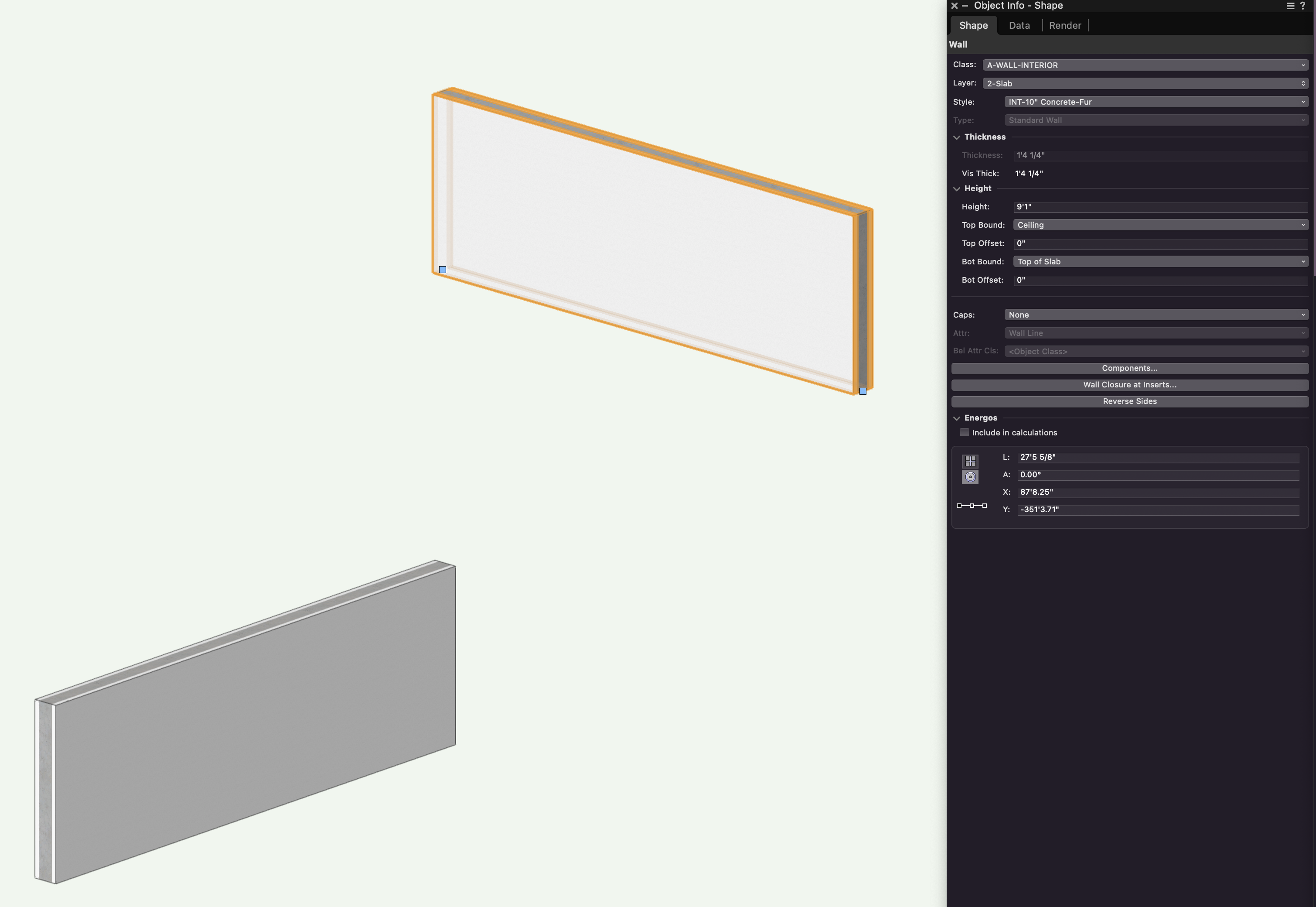
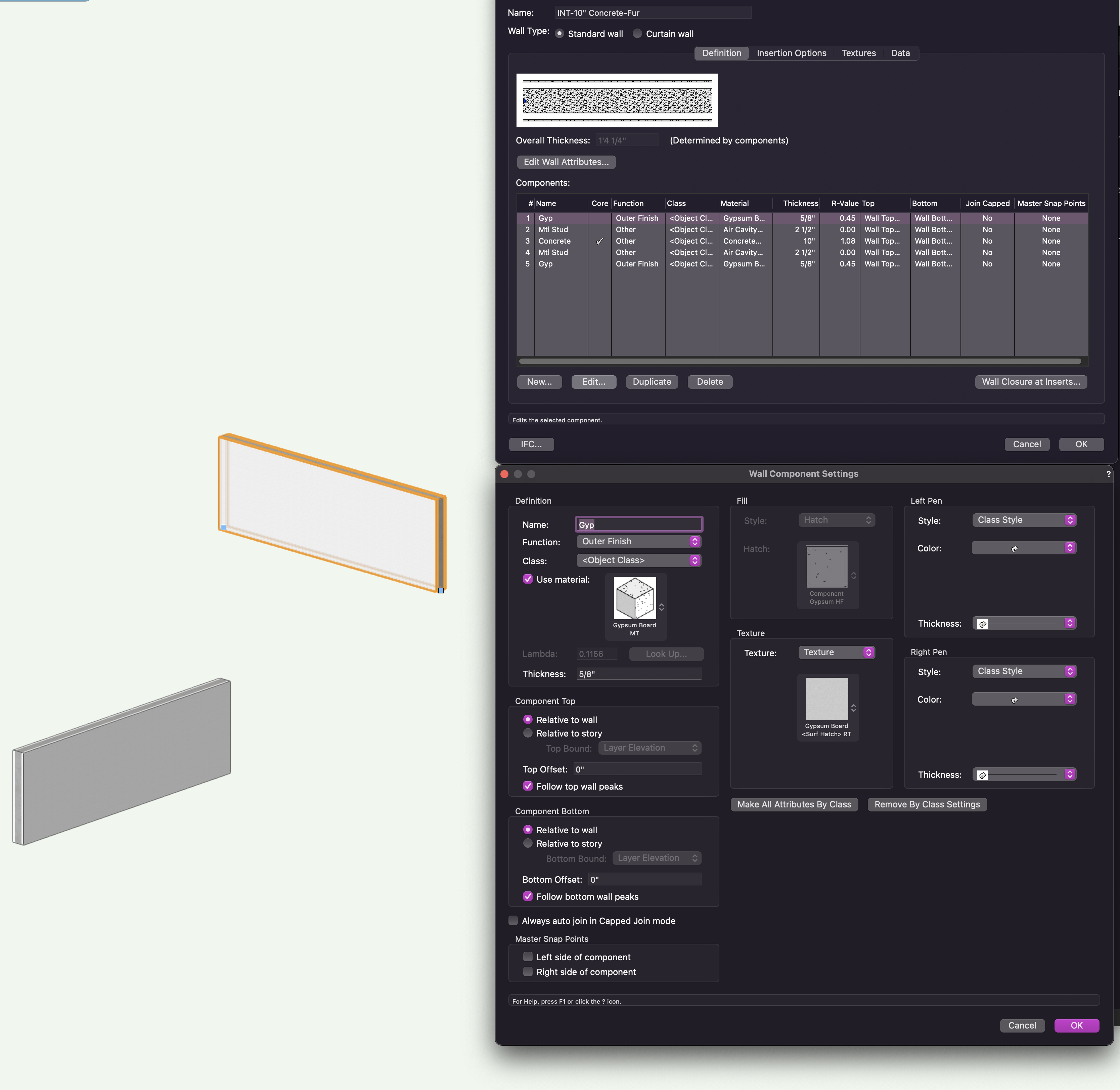
In one file, only, a full list of the file's classes is not available when trying to change the class of a wall component. Just a very few classes show up in the drop down list, as defined by one particular class-filter. I worked around by opening a file with the same total classes and imported the wall to be edited. Changed the class, then imported the edited wall back into the first file. So it's not a Vectorworks issue, but maybe some sort of document issue. But I cannot find any setting in Document Preferences which changes this strange behaviour. But whilst looking at Document Preference settings encountered the same problem when trying to set dimensions to draw automatically in my preferred class... ...just wondering if any one else has encountered this? VWX 2024 Update 2. -
Hello all, I am quite an experienced user ( currently VWX 2023 SP7 ) and rarely baffled these days....but unless I am missing the obvious I cannot find a solution. I would be very grat eful for any comments... ...So after I've reviewed the settings of both component and container classes. All visible. Still, none of the wall types on layer 0-Ground Proposed A show their components or the hatches of those components in wireframe rending. They do render normally in Top view. In Top/Plan the components can be seen using the clip cube... ...I imported a wall with the same hatches from another file which also fails to show in this one. So it's a file problem as far as I can see. Both files are in fact started out from my primary template. So maybe copying is an issue. Thank you in anticipation. 231017 289_02.vwx
-
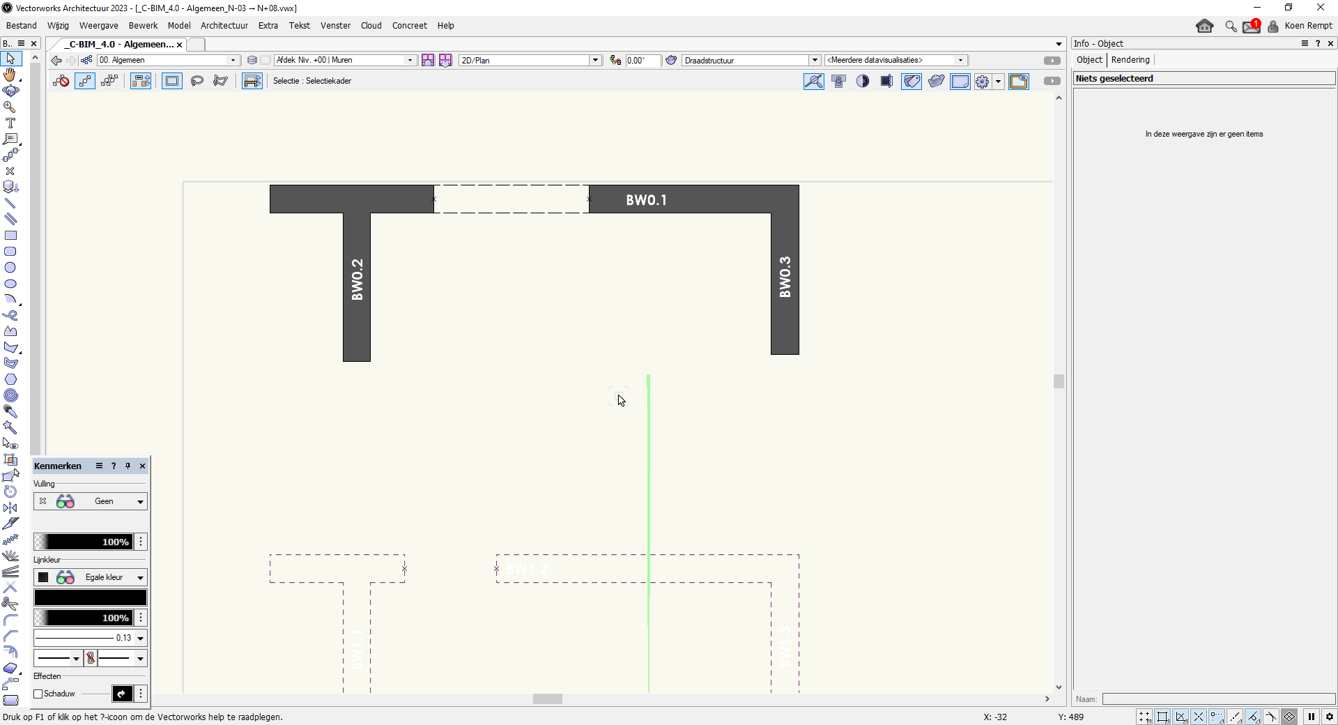
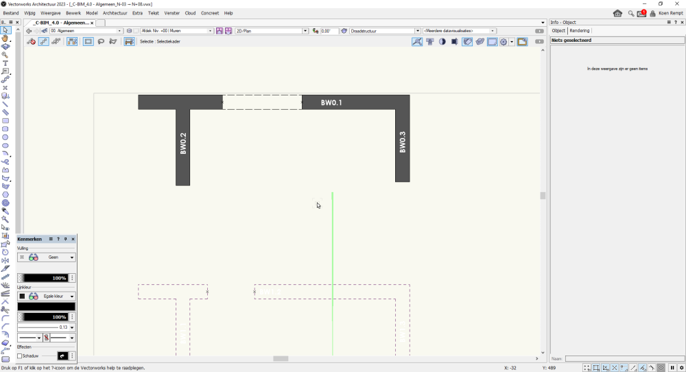
Hello, Is there a way to get de name of the wall where my door is inserted into a worksheet? In the example below my opening should return "BW0.1" so i can easily count the openings in all concrete walls. If not posible with a normal function i am a bit familiar with worksheetfunctions so that could maybe be an solution but this makes the worksheets realy slow so i try to avoid them as much as possible. Thanks a lot! 😄
-
 SPOTLIGHT should have the "convert to wall" option available >>> the polygon and "solid addition" or "solid subtraction" we need to create in the world of Theatre ... but then use it as a wall for scenic and/or venue overlay to a show design. In creating Scenic Items and when drawing out a theatrical/event venue you are making your elements out of available tools. The ability converting them to a "WALL" is something that I would use almost daily... but can't afford the extra $1000 for the Designer workspace for just that ability. (and the Advanced Stair Tool as noted in another thread...) Thank you!
 -
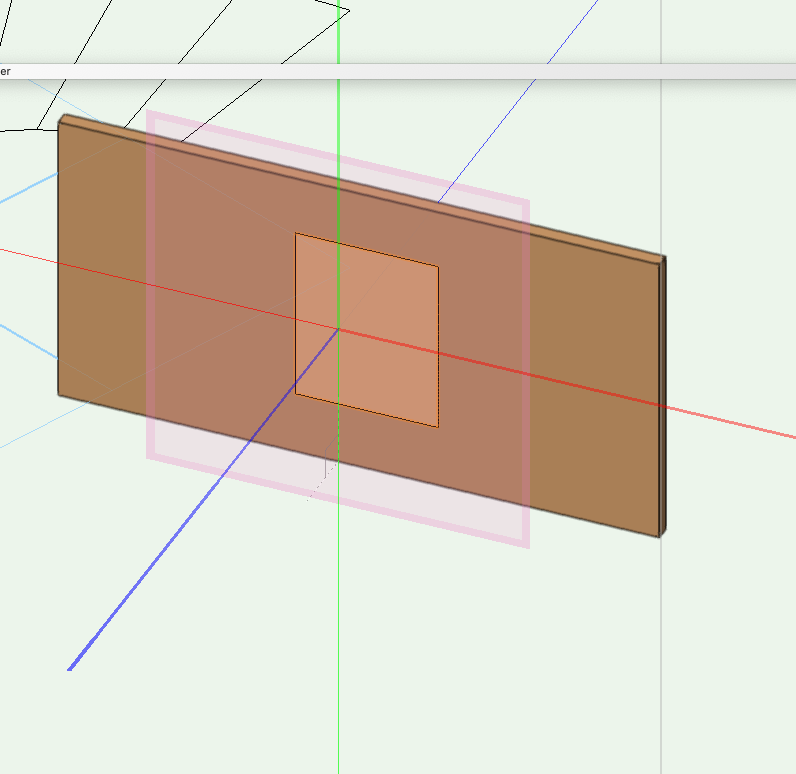
Hi, im having trouble with the text that I want to have on my architecture document. Im trying to write some text and putting it on a wall vertically in 3D, I am able to get the text to 3D but when I try to move the text or modify - rotate - rotate vertical, the text goes at some angle and is not vertical and Im unable to put it on the wall, can someone give me advice? Best regards
-
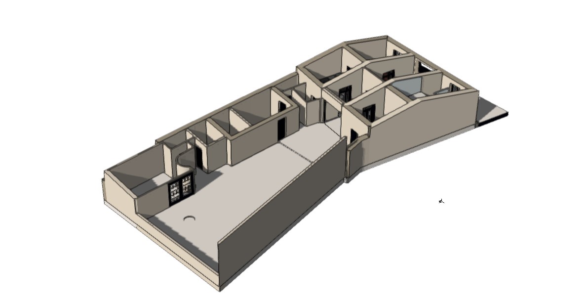
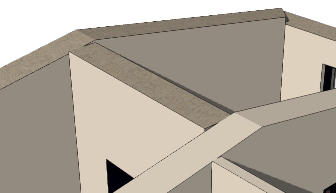
Hello! I wonder if anyone can help. I am doing a scan-to-BIM project and we've surveyed an old house with crooked walls. I am having issues with the accurate modeling of the walls. The 'wall join tool' is not giving smooth results and I wonder if it's something I am doing wrong or VW gets confused in the joining process with walls that are not square. I am attaching some screenshots in case someone can help. (i've used the 'fit walls to objects' tool and fitted them to the roof..) Thanks, Demetris

-
Hello, Is it correct that you can only overwrite the outline of the wall component in section an floor plan but not in isometric views by class? So we have to set the class existing-wall- exterior to 0.10 and then overwrite the class in floorplan to something like 0.35 mm? And not the other way round (class with 0.35) and viewport class overwrite with 0.10 to get a fine line in an isometric view?
-
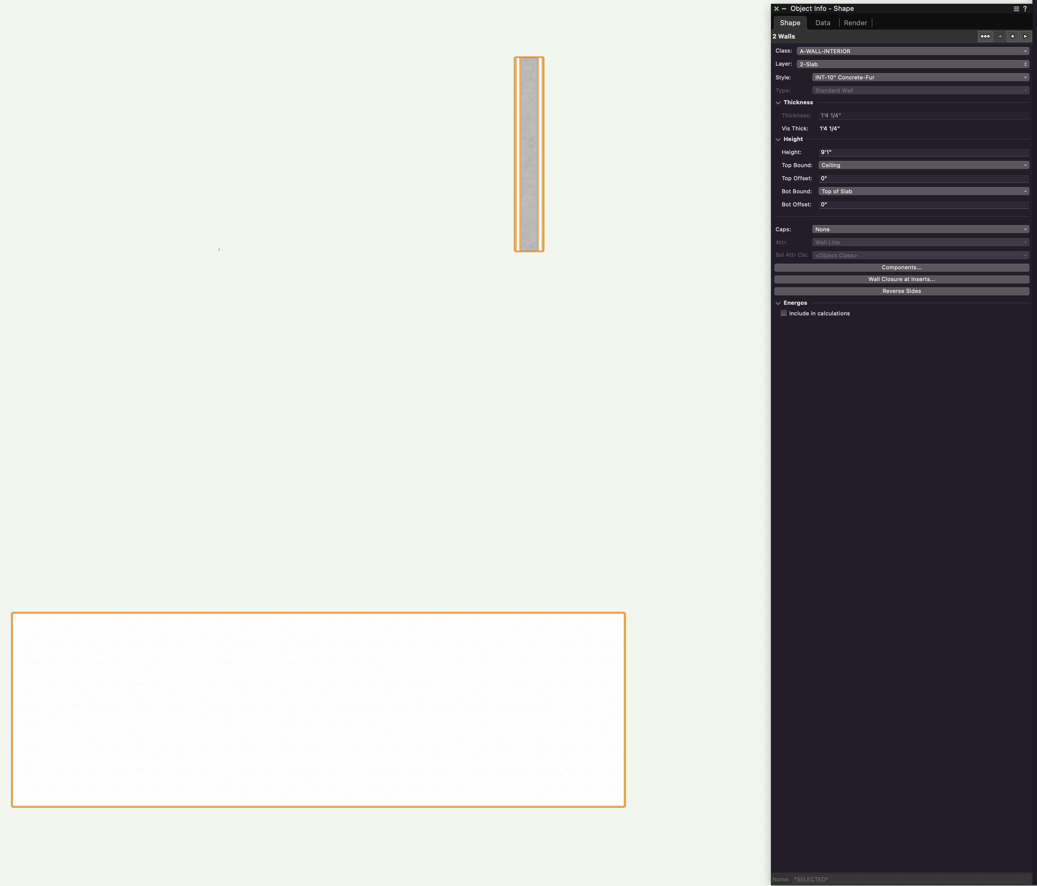
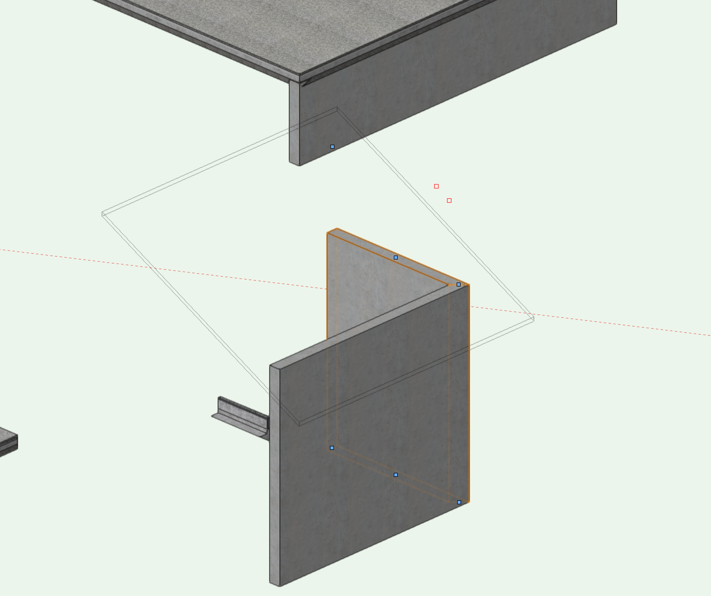
 Hi everyone, I have created a 'hardscape' element below in green with walls on the right. The 'hardscape' element is now aligning to the bottom of the wall with site modifier tool. How do I align the hardscape element to the top of of the wall instead of bottom? TIA for your help. Cheers, Nicole
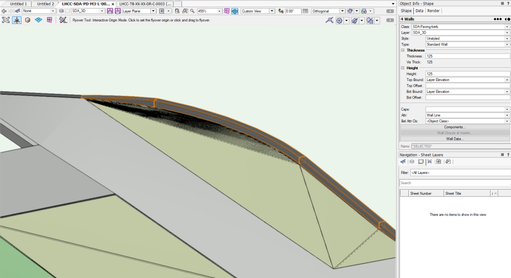
-
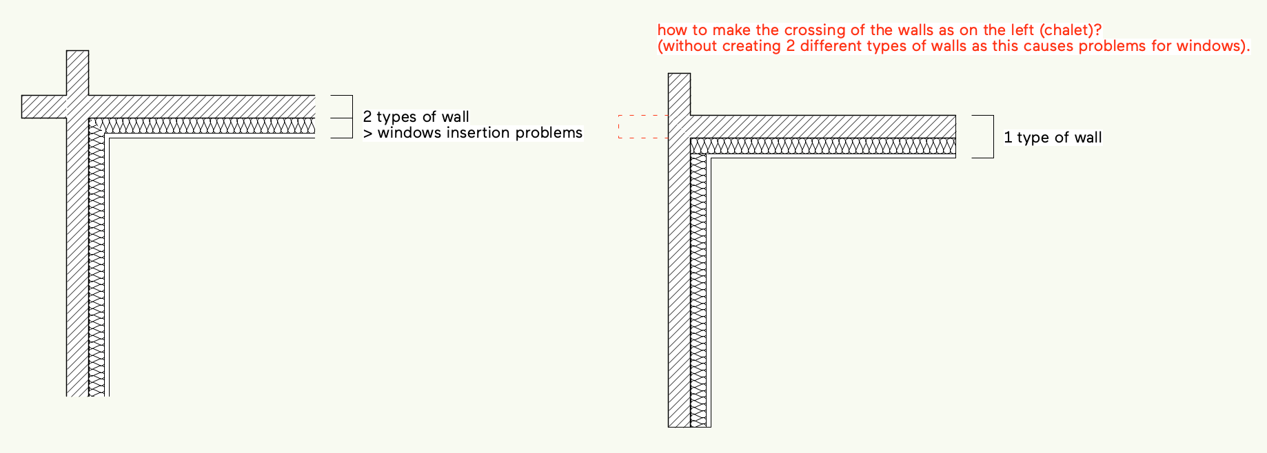
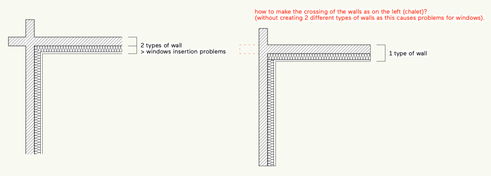
Hi, I’m working on an existing chalet in the french Alps. It has a particular structure with crossing pieces of wood. I don’t manage to make it with Vectorworks. How can I make the crossing of the walls without creating 2 different types of walls ? Did I missed something ? Or maybe that will be a Vectorworks enhancement ? thanks ! LUG-test.vwx
-
Hello, this is the first time I try to work with Vectorworks in 3D. When creating a section viewport I see the wall with a VERY thick line in one floor and a very thin one in the other floor. Does anyone understand who's going on? I'm using the same wall style in both floors. Gal OMZ_Sections.pdf
-
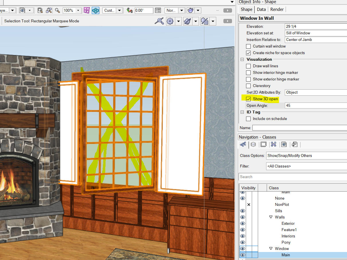
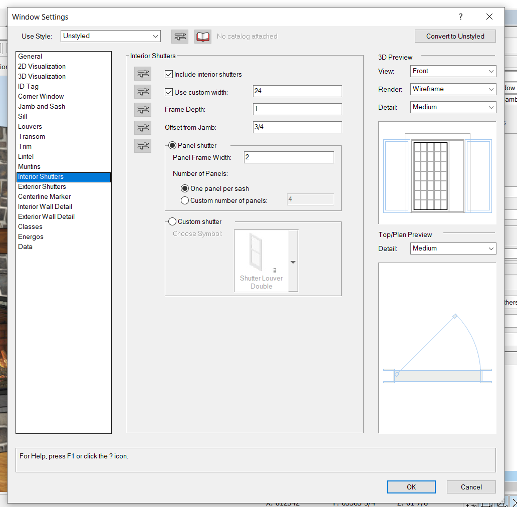
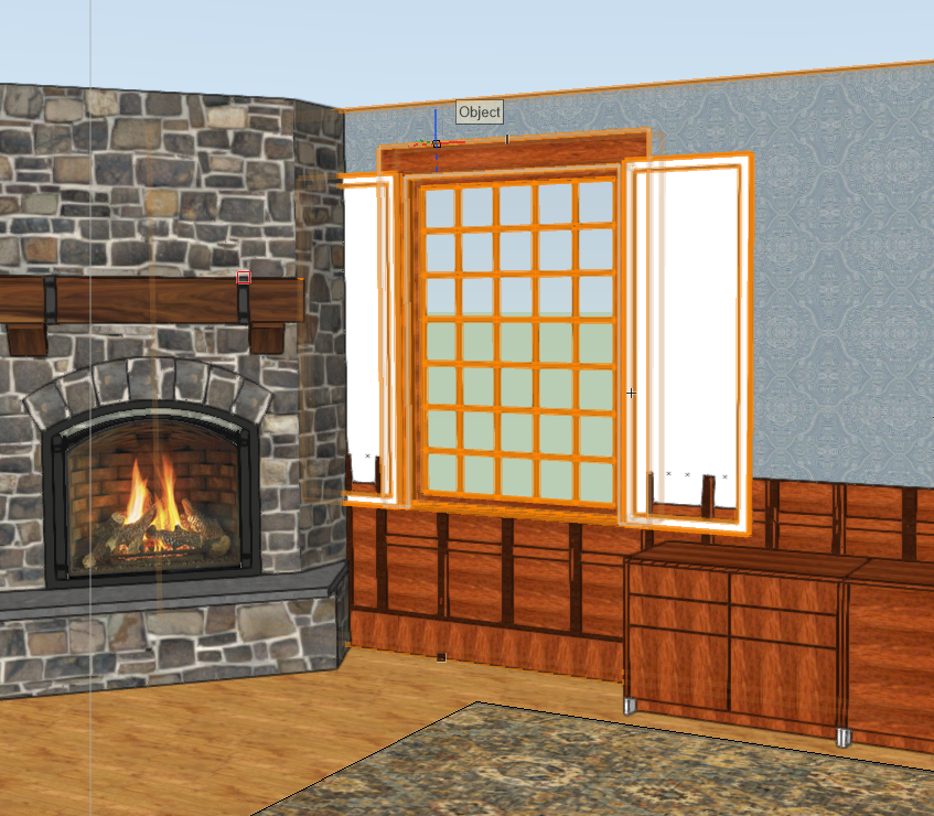
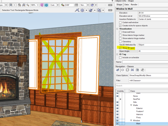
Does anyone know how to open just the window *shutters* in 3D? If I set the window to open, the inside glass opens which is not what I want. Without opening the shutters, millwork and other things show through them. I would also LOVE to be able to easily make these shutters bifold; currently that's not an option. You can change # of panels but that just splits things horizontally, not vertically. I don't see any option for this in Window Settings either: Hoping some VW folks see this 🙂 Thanks! Marci

-
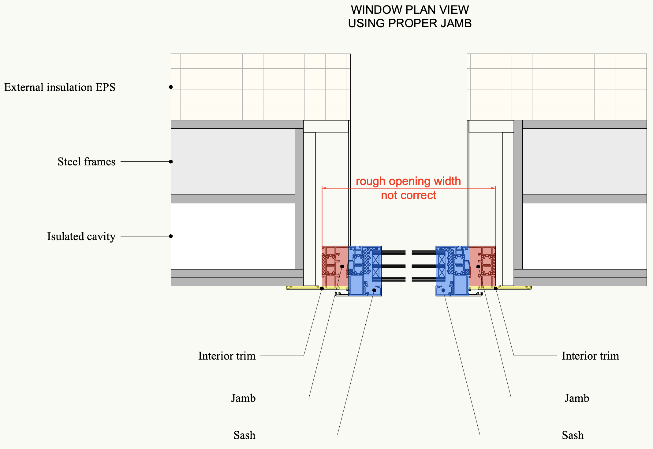
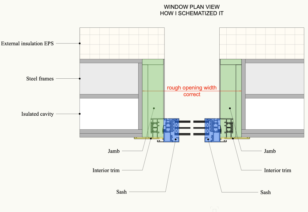
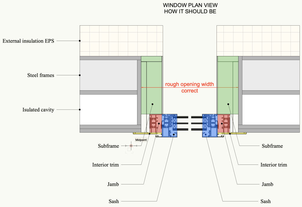
Hi everyone, I'm writing to try to understand how I should represent using the window tool the subframe (also called false frame) of an aluminium window. I would like to schematize the detail I received from the manufacturer using the window tool parts. I need to schematize the subframe to give the correct wall "hole" (rough opening) value to the building company that has to leave the right empty space in the framed structure to install the windows later. The wall structure is made of steel frames, similar to "light steel frame" by Knauf. Can anyone help me? I used the jamb to create the correct Rough Opening Width and the Rough Opening height (attached) but I know it's not the correct way to do it. Any ideas? thank you, Martina

-
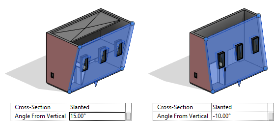
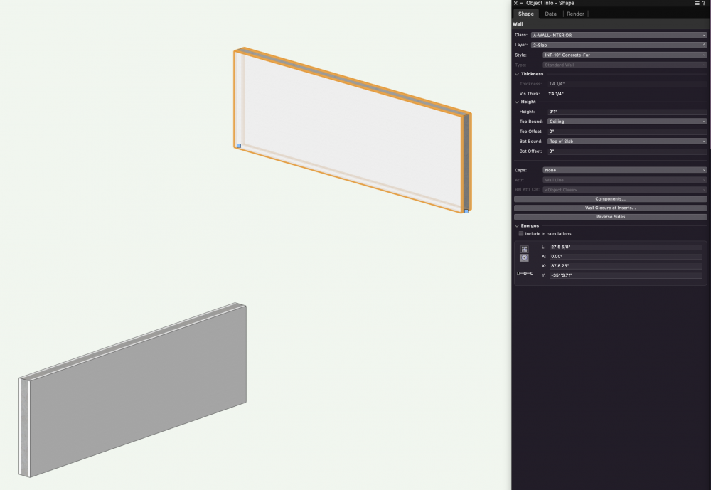
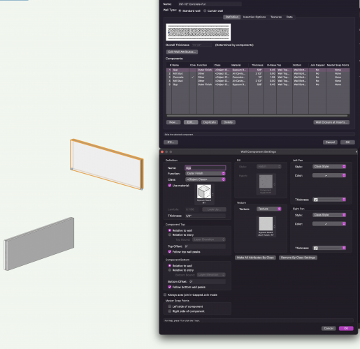
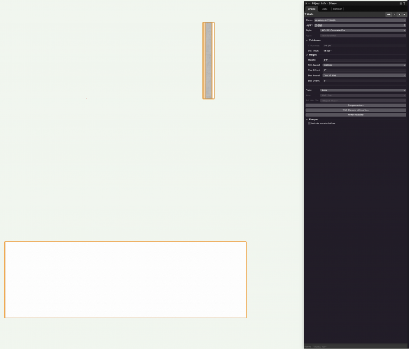
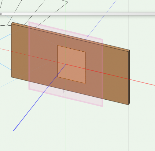
Dear users, I'm just starting my journey with VW and I would like to know how to do a slanted wall and a slanted curtain wall. I'm sure there is an easy way, but I cannot find it. 😅 I've added an image just as an example.

-
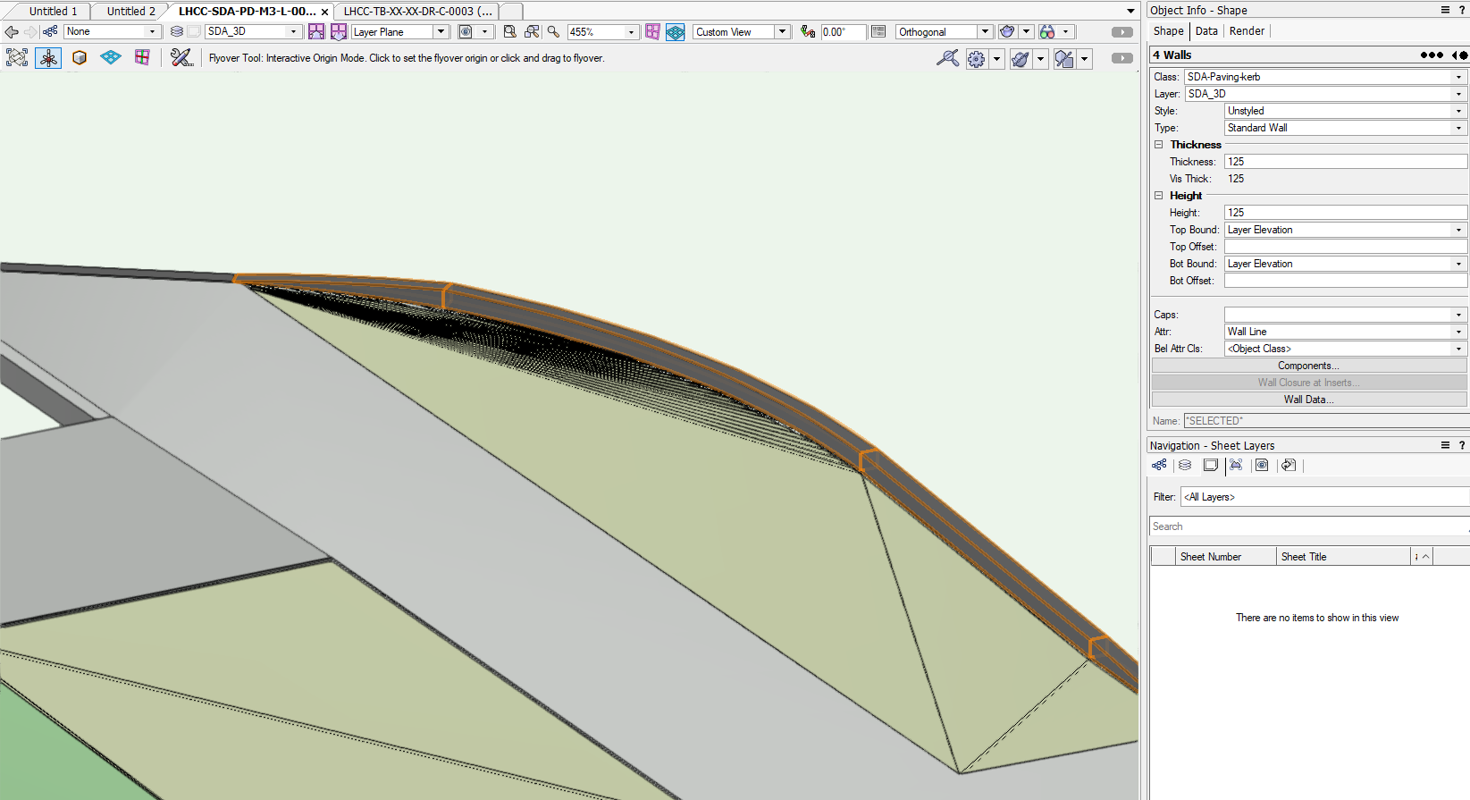
Hi all ! Little practical question, do you know how is it possible to use the wall projection tool on a roof profile. I'm not talking about skylight or dormer but about the wall projection tool (in my case to show the modulations and variations of steel sheet that make up the roof on the 3D). Thanks you for your help !
-
Walls bound to identical layers display at different heights
Apoc Dujour posted a question in Troubleshooting
Hello all, Although I am not convinced this is not a user error on my end, I seem to have somehow created two identically bound walls, of identical type, that are set to different heights. All components of the wall type are bound relative to the wall, top and bottom. Any help or insight appreciated, thanks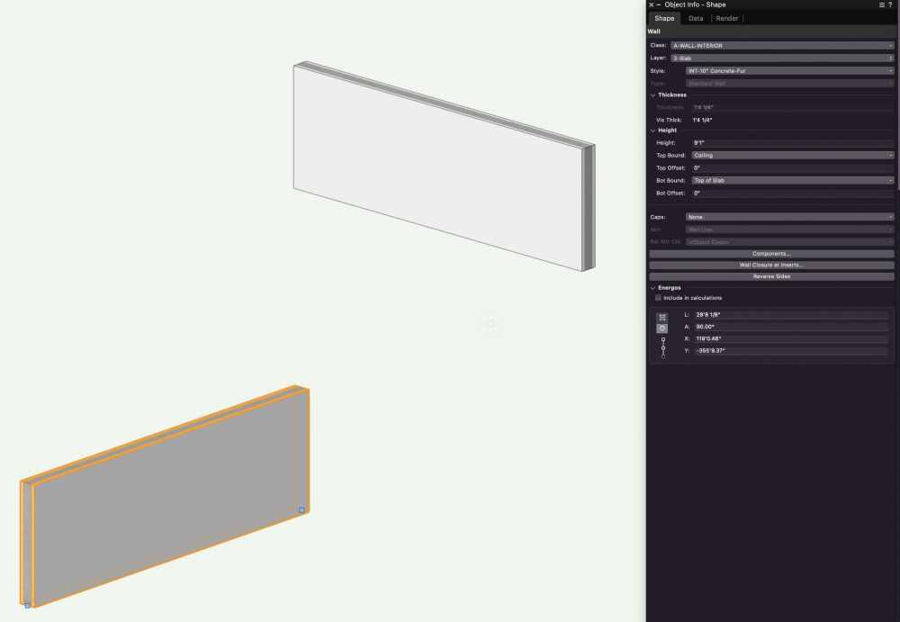
-

Wishlist - Wall with multiple wall styles
Gregovitch posted a question in Wishlist - Feature and Content Requests
Would it not be great if it was possible to have multiple wall styles in 1 wall? In theory, a wall has 3 parts: side 1 + wall structure + side 2 . Each part could be a wall style for example : Exterior cladding + 2x4 insulated structure + Interior furring & finish When you create a door or a window it would create an opening in all of those and act as 1 wall when moving it around. I feel like this could simplify so much the wall style list and allow to not have so many duplicates with small variations. -
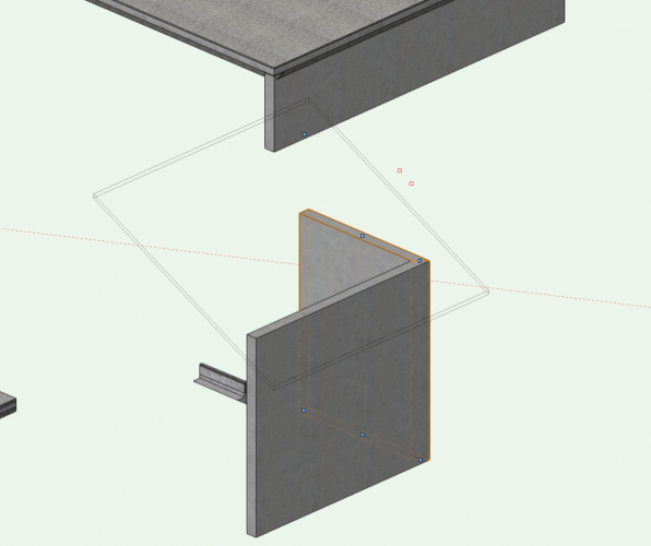
It seem like certain files have difficulty properly displaying sloped walls. You can see the grip floating up in the air. In this case I tried fit wall to object, it appeared to work other than actually displaying the wall properly? I've had this occur frequently enough to notice, in multiple files since beginning with VW in 2014. I've also had the same issue simply dragging the grip vertically, too.
-
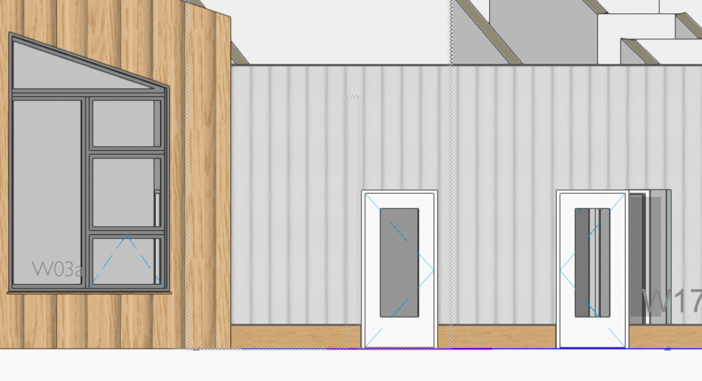
Hi all, I duplicated a previous window style and modified it to the way I want it. Everything's good except the trim doesn't show. Its class/layer is the same as all other windows, and if I replace this style with a different style that exists elsewhere in the project (and shows properly), this spot doesn't appear properly. I've attached a picture of the window I'm talking about (next to the door; it's a sidelight). This window can't be part of the "light" option of the door next to it since its sill is at a higher elevation. Cheers and thanks, Hunter
-
 Hi, So, a couple of thoughts: 1. If I combine all walls, slabs, pillars and stuff to one piece of combined solid, will this make a lighter file? 2. If so, how do I do this? I want to make one piece of solid made out of all the walls and slabs I've created. 3. Is this even a good idea? I'm making an arena, so there's gonna be a lot of stuff in the final file, so it needs to be lightweight and easy to understand. Thanks!
 -
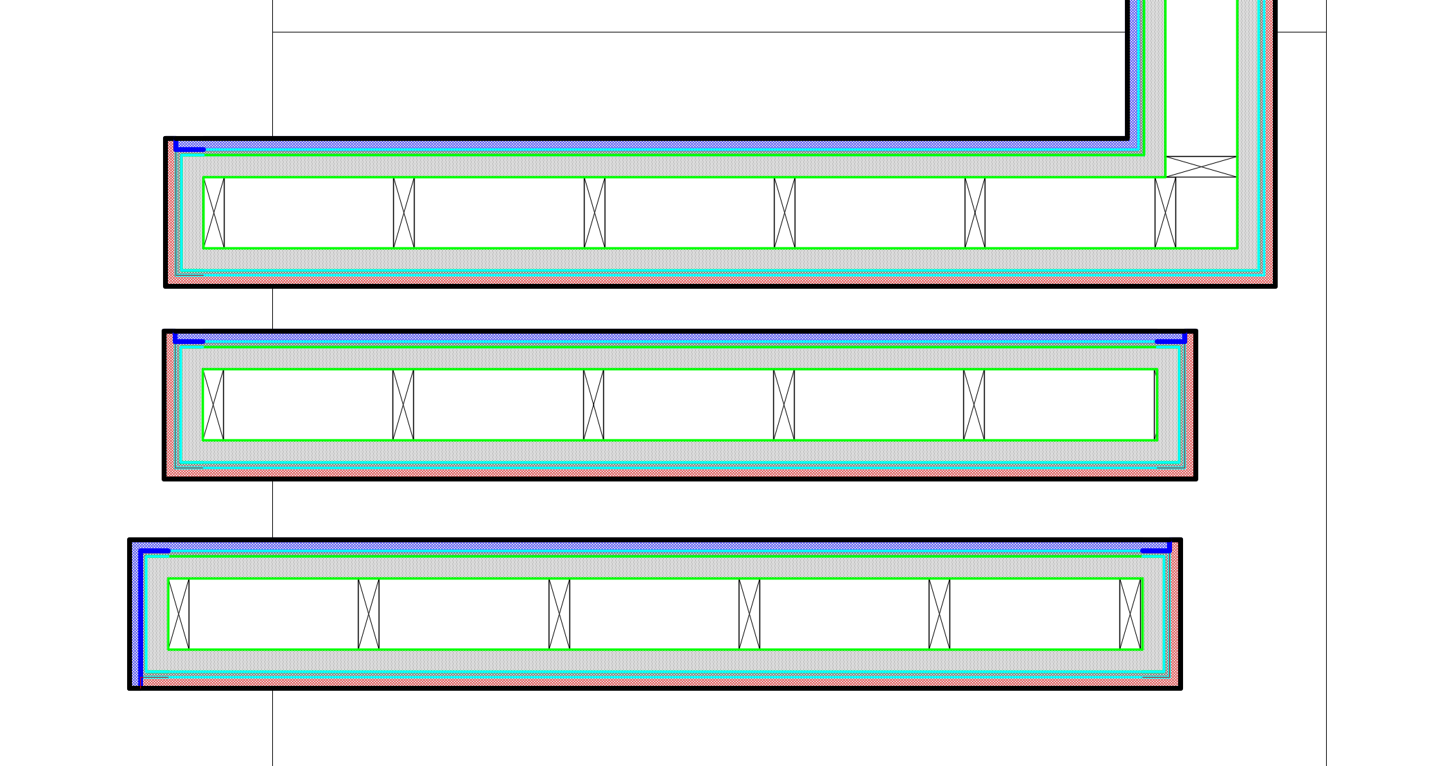
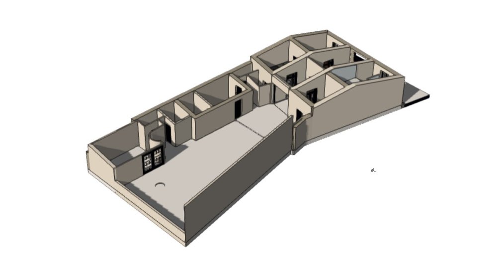
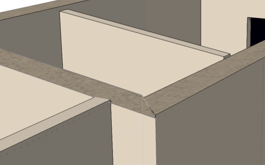
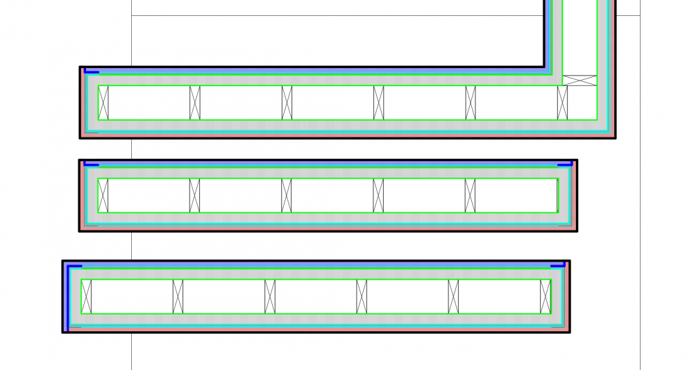
I am having issues with wall end caps, I tried adjusting with allotting I know and I can't figure out what is wrong. I have included image of what is happening, I can connect wall without a problem. The image shows 3 images of the same wall type with exactly the same settings. I color coded different layers of the wall to better see what is happening. Additionally it looks like there are some inconsistencies for no reason - I used end cap tool exactly the same way on all of them. The blue and red are outer and inner finishes, the line thickness is set to thin, but shows as thick, I solved the problem by setting line thickness to NONE, but why is this happening?
-
I am setting up more elaborate wall types. Similar to Batt insulation I am using tiles for various items, one thing I unable to control is the scaling, for example if I have a stud 2x4 and I have a tile set with actual stud dimensions it shows scaled in the wall, it seems like 6" width fills the wall regardless of the wall thickness anything else is off. Is there a way to control that?
-
Can someone remind me of the quick command to make a hole in a wall in 3D instead of using Subtract Solids. I have the answer for anyone who needs to know. Ensure the AUTOMATIC PLANE is on. Push/pull and use hold down ALT, click enter. Thanks,
-
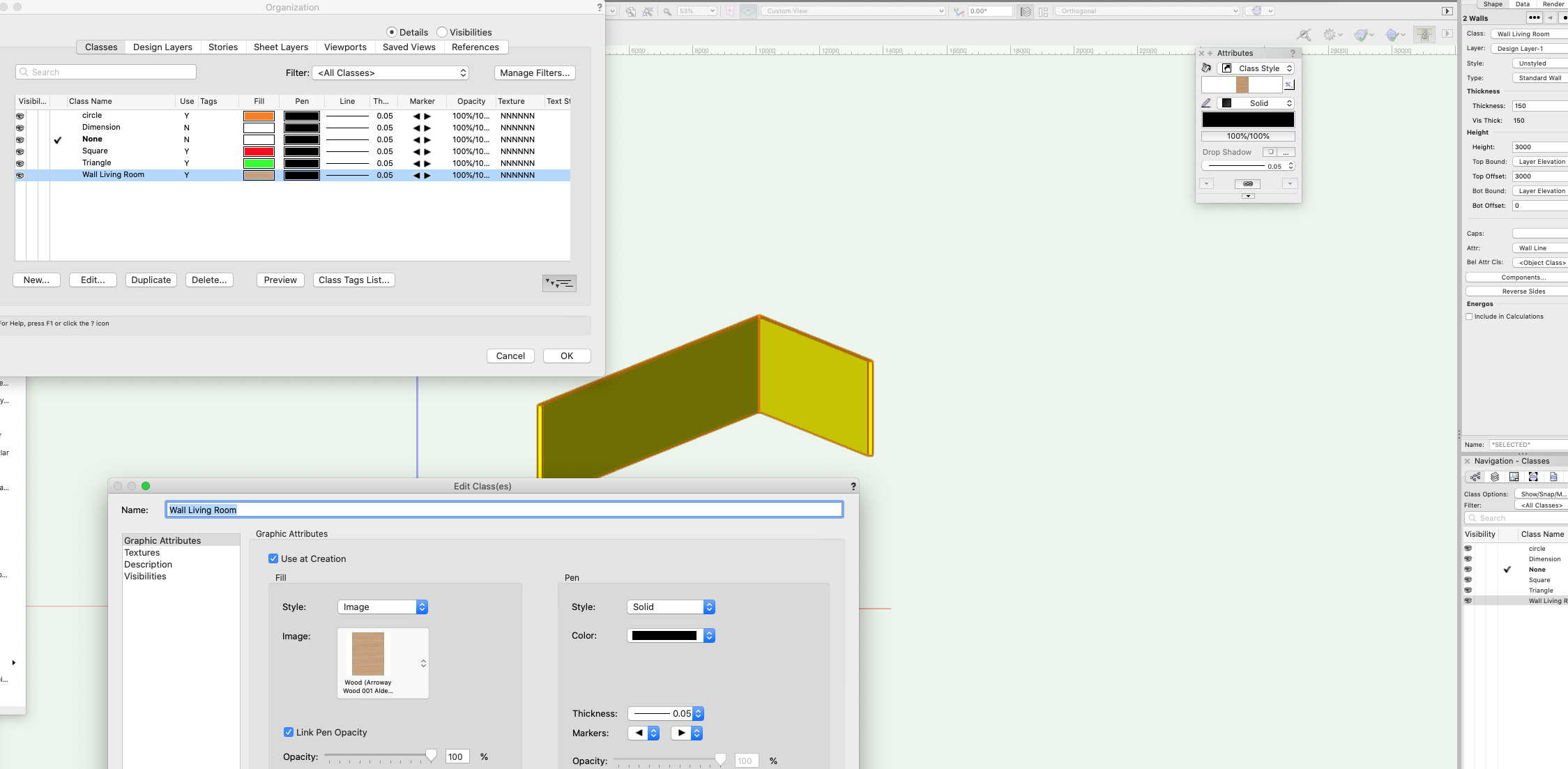
HI, I can't seem to apply a class (image) to a wall. I have no issue applying a solid colour but for some reason If I need to apply an image this does not work and defaults back to a colour. The wall is classed but I have no idea where the yellow comes from. I can render a wall with whatever image but when I apply class texture this does not work, even though the class is set (as it works with any color fills but not image fills). Photo attached. Anyone has any idea as this must be a simple thing which I did not grasp! Thank you,

-
Hi all. This viewport is rendered background=unshaded polygon. Has anyone experienced the unwanted diagonal lines, indicated in green, attched? Seem to be associated with a re-shaped wall....any comments welcome. Rendering in opengl solves the problem. (I used unshaded polygon because it renders two extrudes semi-transparent, the ones showing existing gables of this extended house.) 200511 GA Tech 1.pdf
-
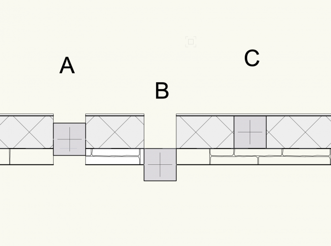
Can you put symbols or PIO's in just one (or specified) components of a wall? e.g. in the attached image, I'd like to insert a column into the CMU blockwork component in the middle of the wall - like column 'C' which is not actually inserted, but 'on top' of the wall in 2D. The only insert options I find are in the Object Info palette : 'Centre line' (column A) and 'Left edge' or 'Right Edge' (Column B), both of which are inserted / offset relative to the entire wall, and not the preferred wall component, and create a hole in all the wall components... Am I missing something? Thanks, hope all are keeping well in these strange times, and best wishes to you and your families. S