CipesDesign
-
Posts
5,153 -
Joined
-
Last visited
Content Type
Profiles
Forums
Events
Articles
Marionette
Store
Everything posted by CipesDesign
-
JC, here (below) is a VW's file with the Evergreen Tree. Note 1: see how it behaves like a 2d Object in Top/Plan View and how it changes to a 3d Object in 3d Views (this is a central paradigm in VW's and applies to the entire program); Note 2: if you double click on a Hybrid Symbol you are given the choice of Edit 2d or Edit 3d. Try it and you will get a better idea of how Hybrid Objects are created. You will also be able to modify many things in the Symbol if desired; Note 3: If/when you create/modify Hybrids, make sure that the 2d alignment is true, center of 2d = center of 3d. More questions? Post back! Evergreen.vwx
-
In Top Plan View, IP's look like crossed lines, but pop into a 3d View (like with the Flyover Tool) and you will see their 3d(like) presentation. If you want the best of both worlds, you can use a 2d/3d Hybrid Symbol which contains the Plan View graphic and the 3d IP. For example, try the Symbol called "Plant Basic Evergreen Tree 01". Or, you can create your own (see: http://app-help.vectorworks.net/2019/eng/index.htm#t=VW2019_Guide%2FSymbols%2FCreating_Symbol_Definitions.htm&rhsearch=hybrid symbol&rhhlterm=hybrid symbol&rhsyns= )
-
Image Props are 3d resources. They have a much lower poly count than actual 3d models. Try it and see what you think... FWIW, it is generally helpful if you create a Profile which includes your OS flavor and version and your VW's Version, etc. P

-
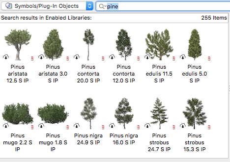
Yes. Use the search function in the Resource Manager; type in "pine".
-
LIne Weight is controlled in the Attributes Palette.
-
One way to do it is: Create Viewport, on Sheet Layer and draw the Crop as a Polygon that exactly outlines the portion of the building you wish to show. Make the Crop visible and make sure to adjust the line weight of the Crop to suit the rest of the plan.
-
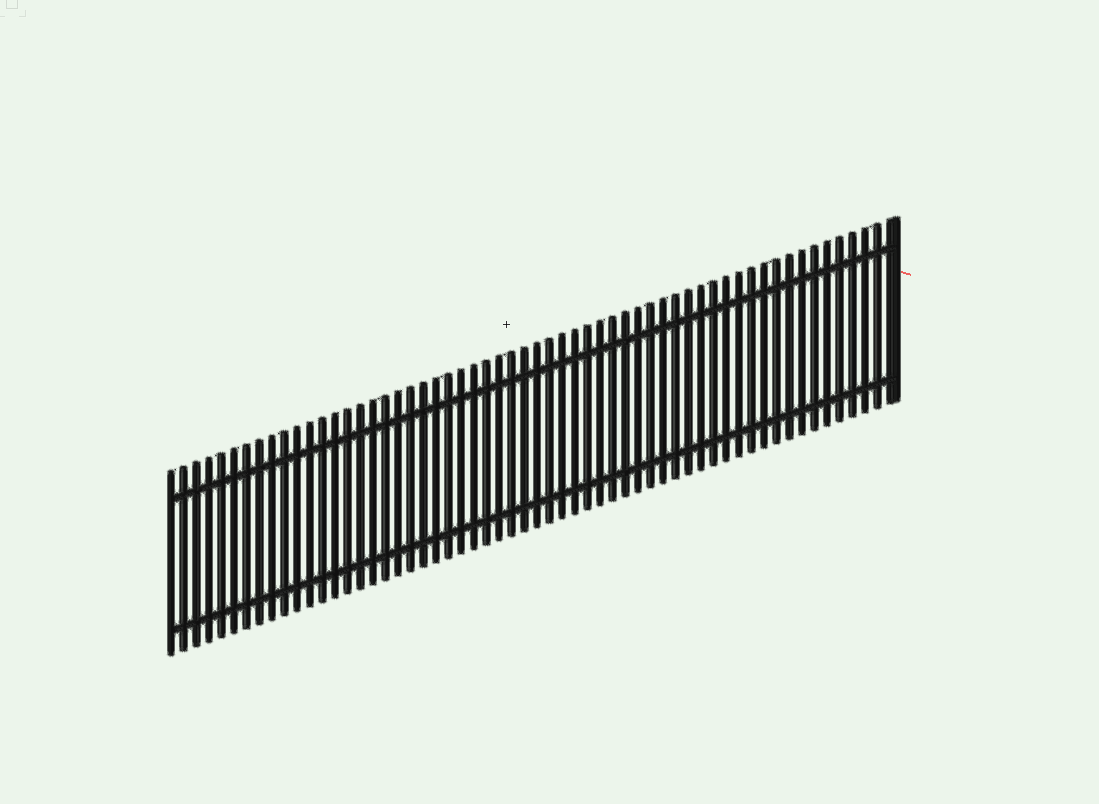
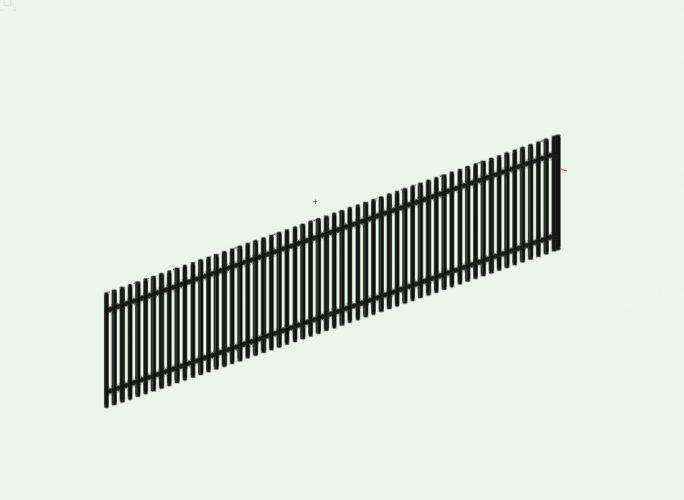
Not difficult. You just need to fiddle with all the settings. Here is an example. A couple notes: 1) I used the Handrail Straight tool; 2) Since you cannot remove the Top Cap, and it cannot have "0" value, I cheated and made it .01 x .01" (this will present well in Open GL, but unfortunately shows a line in Hidden Line render mode. That would need to be fixed with a mask in annotations); 3) Dimensions for horizontal rails can be set as desired, see attached VWX file; 4) In order to show larger posts (as in your photo) you will need to create Pillars (or Floors, or Extrudes) and place them along the line at the interval of your choice, then the whole set can be Grouped for ease of handling. 5) If along a sloped path you can adjust the "Rise" of the Railing Object, but you will also need to manually (or carefully Duplicate Along Path) the periodic larger posts to conform. or 6) for a stepped fence (as you show) you will need to use multiple separate pieces, carefully aligned in a frontal view to follow the slope. All of these can also be grouped if desired. [Side Note: This whole thing would be a very good exercise for a Marionette Object] Post back with follow up questions as needed. Wrought Iron Fence.vwx
-
What font is that? Maybe you try a different one?
-
I would need more info to diagnose this. There are too many variables to sort without poking around in the files.
-
Chris, if you could post a file it might be helpful. Your issue could be caused by at least a few things and guessing without looking at the file will be a shot in the dark at best, at least for me.
-
Best way to insert exterior walls into a site model?
CipesDesign replied to Phileas's topic in Architecture
Although Site Modifiers cannot actually touch, they can be VERY close to each other. In this situation, which is pretty common, I would suggest placing your different height Pads about 1" apart from each other and surrounded by a single Grade Limits Object, with the 'seam' at or near the center of the wall. This will result in a slightly sloped (non-vertical) step, but the step will be hidden by the wall. It will throw off the Cut & Fill calc's by a hair, but if done with care it will present well visually. Some time ago (years I think?) I posted a much longer explanation of this, but I couldn't find it. I think this should give you the basics. Post back with follow up questions as needed. P -
My continued 2¢: Often the data received from survey files is incorrect, sometimes due to something as simple as sloppy drafting. So to ensure I have good data, before I create a Site Model I follow this procedure: 1) Find all of the topographic lines (either 2d or 3d). Usually they will be be in two discreet Classes, "contours major and contours minor", or something like that. 2) Select only those lines and Copy and Paste in Place into a new clean Design Layer. 3) Manually check each and every contour line for a) continuity; b) elevation (Z value) if 3d; c) also make sure there are no "self-intersecting" polygons. d) check, by deleting (then undoing) that there are no coincident duplicates. This can take a while. Sometimes it's faster to Copy and Paste in Place one at a time. 4) If necessary, Convert 2d Polys to 3d Contours. 5) Once you have a clean set of 3d Polys, select them all and Create Site Model. If you are (or desire to be) working from 3d Loci the process is different, but the goal is the same. You need to verify the source data. Since I don't usually work from 3d Loci I will leave it to others to chime in with specifics. There are probably other things that can go wrong here, but those are the basics. Sometimes I actually go to the trouble of tracing each and every poly, then use those to create the Site Model. Hope that helps.
-
Usually when this occurs there is some data WAY below the rest of the model. IE: one little piece of 3d Polygon with an incorrect Z value. Go into a side view and zoom all the way out (fit to objects) and you can usually find the culprit. Then Edit Site Model to correct (or remove) the offender.
-
PROBLEM - Drafting in Color / Publishing Black & White
CipesDesign replied to CW2020's topic in General Discussion
On a Mac, I draft in color, and print in B & W, as follows: Print To PDF (using Mac built-in PDF writer, via Print Menu); open PDF in Preview; Save As applying Grayscale Filter. Works like a charm. However there are certain colors that I have learned from experience print darker than expected, so I stay away from those. -
Try this: with nothing selected, go to the Font menu and set the Font; Style; Size, Etc. to your desired defaults. Subsequent new text creation should now be as you wish. To change the existing text, do the same things, but with the existing text selected.
-
window/door in horizontal section viewport issues
CipesDesign replied to drelARCH's topic in Architecture
I would recommend filing this as a bug. It seems to me as if that portion of the geometry is being incorrectly calculated in that context. -
Or, try the Convert Text to Polyline command. After conversion I usually Extrude the resulting polys, giving them a bit of thickness. Note: this will result in a 3d object(s) which is/are no longer editable text.
-
Why do my doors keep jumping out of the wall?
CipesDesign replied to Ride's question in Troubleshooting
Hi Pat, Thanks for that. Yes, but in the past a simple (offset) dupe would be created up and to the right, and not 'in wall'. Now I need to drag the dupe out of the wall then back in to another wall. More clicks/drags = time suck. Oh well... -
Why do my doors keep jumping out of the wall?
CipesDesign replied to Ride's question in Troubleshooting
I agree that this issue did not occur in VW's as of a couple/three versions ago. Now it is fairly persistent (and annoying). While we're on the subject (sort of), it used to be that if I duplicated (command+d) a door or window the new object would be created up and the the right, and OUTSIDE of the wall. Now the new objects are created in the wall, literally nearly on top of the original. This is frustrating. Is it just me? Is there a setting I am missing? -
Section Viewport with turns / interior unwrapped elevation?
CipesDesign replied to MattG's topic in General Discussion
Hi Matt, I think there are two ways you can do this. First is what Matt P (and I earlier) suggested: multiple VP's placed next to each other. Second would be to create another Design Layer, then actually unwrap your runs, then create one VP along the unwrapped run. This of course means higher maintenance if/when changes occur... -
Section Viewport with turns / interior unwrapped elevation?
CipesDesign replied to MattG's topic in General Discussion
Right. Well there's always a way to do it. Just gotta be creative. I'd be curious to see what your project looks like if you're game. -
Section Viewport with turns / interior unwrapped elevation?
CipesDesign replied to MattG's topic in General Discussion
You can jog a section line, after creation, by adding vertices to it (but I'never tried one that actually wrapped around more than 90º). However, I think it might be easier and perhaps better to use three separate sections, cropped and aligned next to each other as desired. If done carefully it can be made to look like one section. -
Use one continuous main wall, with a window in it. Set the window type to "Opening".
-
Unfortunately you cannot do this in VW - unless you resort to manually placing (or modeling) muntins. [This would be a good wishlist item!]. The easiest way for me is to go to a frontal view, change to Screen Plane, draw the 2d muntins/grid, Extrude, then go to top plan and drag/move the Extrude into place (b/c Extrudes are always crated at 0/0/0 in space). You can subsequently turn the Window and Extrude into a Symbol if desired. It's not the worst workaround but certainly would be nice if it could be done natively in multi-unit windows.
-
This might be quite helpful: https://www.vectorworks.net/training/2019/getting-started-guides/the-basics