Nina Ivanova
-
Posts
348 -
Joined
-
Last visited
Content Type
Profiles
Forums
Events
Articles
Marionette
Store
Everything posted by Nina Ivanova
-
@amberhine, this message would appear, if you are trying to open the file. If you want to import a DWG file, you have to use menu command File-->Import-->Import Single DXF/DWG...
- 1 reply
-
- 1
-

-
Hi Mike, Thank you for the file! I was able to see a delay while reading 3D solid entities and creating Vectorworks Generic solids - which is in general a slower operation. The DWG also contains more than a hundred layouts, each one containing 2 viewports - and creation of the viewports also takes time. There is a delay on the final stage of the import (Finishing... stage), which is due to the centering on internal origin procedure. We usually recommend to Center the drawing on import, especially when there are objects far away the internal origin, but if you want you could avoid this using the location import option Align with Internal Origin. After the import you could center the drawing using menu command Tools-->Origin-->Center Drawing on Internal Origin. For this exact DWG imported graphics corresponds to the graphics shown in AutoCAD and there is no difference between Vectorworks 2018 and Vectorworks 2019. Please, if/when you have a DWG, which imports differently in both versions, send it to me so that we can find the reason and fix it. Thanks, Nina
-
Except the numbers, what else is written in the Progress dialog? Would you, please, send the DWG, which demonstrates the problem? This is another issue, just exposed by importing specific DWG files. No DWG import changes were done between the versions, but, of course, from a customers' point of view this is a DWG import regression... We are working to fix it. Please, send a test file, so that we can analyze the differences in our support and fix the problems? Thank you, Nina
-
VW19 - DWG import generates strange result
Nina Ivanova replied to bjoerka's question in Troubleshooting
Hello bjoerka, I believe, that this problem was already for sp3. It is related to the proper regeneration of the drawing - i.e. objects are imported correctly, in their right positions, but due to a missing drawing regeneration graphics does not look as expected. This additional regeneration was not necessary in previous versions, but for VW2019 it has to be done. This problem appears only for some files, which is the reason to not been found and fixed earlier. For now I could propose two workarounds: 1) Import the DWG in Vectorworks and immediately after the import has finished, without switching to another layer or zooming, save the document, close it and then open it again - everything should be regenerated correctly. 2) Import the DWG using the Location import option "Align with Internal Origin". Graphics will be drawn correctly. If you need the drawing to be centered, then use the menu command Tools-->User Origin-->Center Drawing on Internal Origin. (Note: Importing with Location option "Center first import, align..." (for a first import) or "Center on Internal Origin" are equivalent to importing with Location option "Align with Internal Origin" PLUS using the menu command Tools-->User Origin-->Center Drawing on Internal Origin.) If you still have a problem using the workarounds, please, send the DWG file directly to me. Best Regards, Nina -
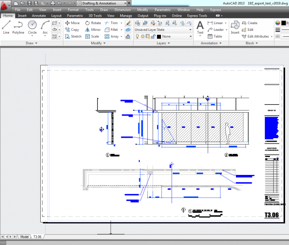
Hi François, Thank you for the file. I suppose, that it is the one, which you used when you firstly wrote to me. When this file is exported with the default settings, for section viewports in the sheet layer you will receive corresponding clipped blocks with geometry in the AutoCAD's Paper space layout. It will look exactly as expected - with the appropriate clipping. With the default settings, we do not write any graphics in the Model space for the sheet layer section viewports. You should not re-import the exported DWG to check the exported graphics - as I wrote in my post, we are not able to crop our graphics in a sheet layer without creation of viewports - DLVPs are not allowed in the sheet layers. If you want the graphics to be exported in the Model space, you could use "Export Viewports as 2D graphics in Model space" export option. This of course will not create the corresponding viewports in the Paper space layout. If you re-import this DWG in Vectorworks, you will receive the graphics properly cropped because we will create the necessary DLVPs. From your second post I understood, that you have created cropped Design Layer Section viewports. If you export from a design layer, you will receive a DWG with clipped blocks. Then, re-importing them back you will receive properly cropped graphics because the necessary DLVPs will be created. This is what I meant in my post. If you create sheet layer viewports presenting the cropped design layer section viewports and export with the default settings, we will create blocks to place there the necessary graphics for the sheet layer viewports (for visibility control) and clipped blocks, presenting the design layer section viewports will be actually inside these blocks. The graphics will look as expected in AutoCAD - you will have both the model space graphics and the paper space presentation - which as I understood is what you want. Again, re-import is not a good check for the exported DWG. On re-import we will not be able to create the necessary DLVPs because we do not support DLVPs inside symbols. That is probably why you have not been able to see what I explained in my post. Regarding the annotations: you have added annotations in the sheet layer viewports, correct? On export to DWG we will place all them as additional graphics over the created viewport. DWG viewports do not have a spacial "space" to put the annotations as we have in Vectorworks. That is way they will be re-imported as separate objects over the created VW viewport. Please, let me know if there is something unclear. Thank you, Nina


-
Hi François, Yes, please, send the files off list, so that I can look at them. Thank you, Nina
-
Hi François, All the section viewports are exported to DWG as ready graphics - i.e. blocks with elements, presenting the section. When the section viewport is cropped, it is exported as clipped DWG block. When a clipped DWG block is imported back in Vectorworks, there are two possibilities: - if the clipped DWG block is from the Model space (i.e. needs to be created in a VW Design Layer), by default it will be converted to a cropped Design Layer viewport (or to a non-cropped symbol, if "Ignore Block clipping import" option is set to ON); - if the clipped DWG block is from a Paper space, like in your case, it will need to be created in a VW Sheet layer, and then it will be imported as a non-cropped symbol. There is no way to import it as a clipped DLVP there. So it is not a matter of a setting. Best regards, Nina
-
Export Import DWG Problems - General questions
Nina Ivanova replied to António da Cunha's topic in General Discussion
Did you try REGEN command from inside AutoCAD?

-
Thank you all for your comments! We will consider your requests. Best regards, Nina
-
2018 SP2 CRASHES DURING DWG EXPORT
Nina Ivanova replied to Wesley Burrows's question in Known Issues
Problematic negatively scaled symbols with attached records, placed inside other symbols, were not fixed. Fixed version of the document was sent via PM. Updated VectorScript can be found in my previous post. -
2018 SP2 CRASHES DURING DWG EXPORT
Nina Ivanova replied to Wesley Burrows's question in Known Issues
Tparabia, Shrunken Ned, You can do the following in order to be able to export your documents to DWG - as a temp workaround until you get the SP3 version where the problem is fixed: Save your document as a new one, just for the export purposes. Create a new resource of type Script. Copy the script from the attached txt file inside the opened Script Editor window, compile and run it (be sure to have Language set to VectorScript). It will detach all the records from the negatively scaled symbol instances and corresponding symbol definitions. If you still see a crash even after you have run the script, then, please, send the original document to me. Best Regards, Nina DetachRecordsFromNegScaledSym-updated.txt -
Vectorworks does not create empty classes (or layers) anymore. Unused block definitions, line types, materials, dimension styles are also purged during the import.
-
@ensta, Are you trying to import all the DXF files at ones, using the Import DXF/DWG or DWF menu command? If you are batch importing all the files, then you might want to check the Destination: Current File, Symbols in Current File, New Files in Folder. If you are importing as symbols in current file, only symbol definitions will be created; if you are creating new files in folder, then you will not have anything imported into the current document and you have to open created documents to see the graphics. You could send an example DXF so I could check what happens.
-
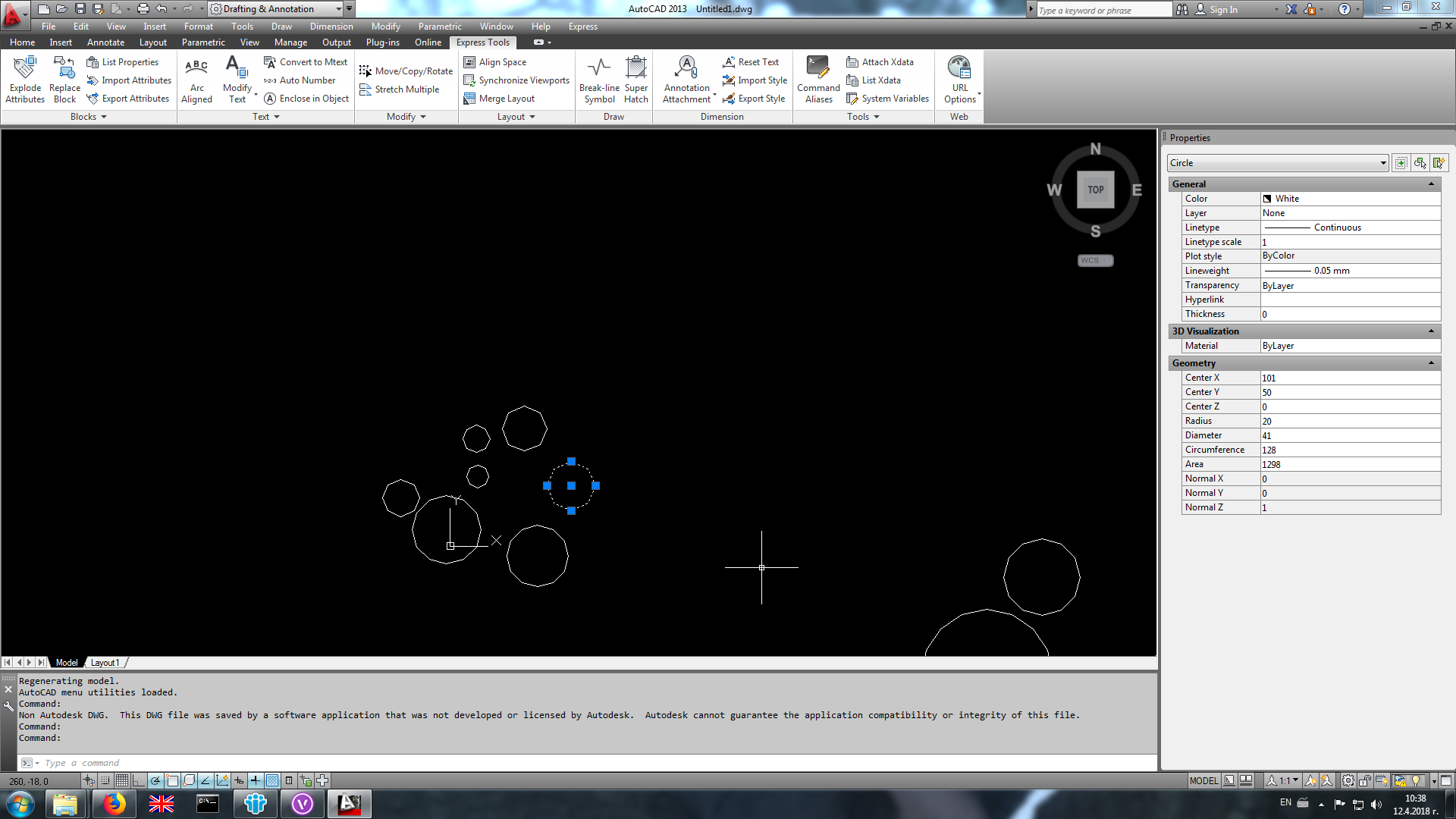
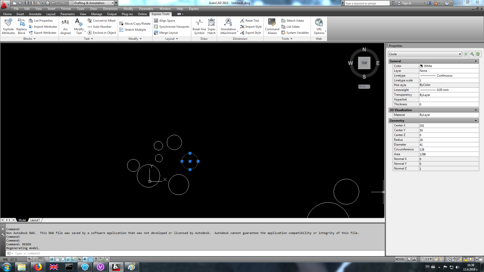
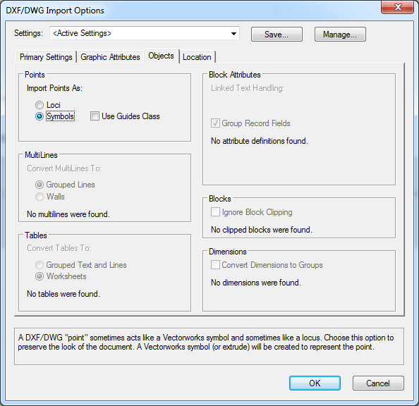
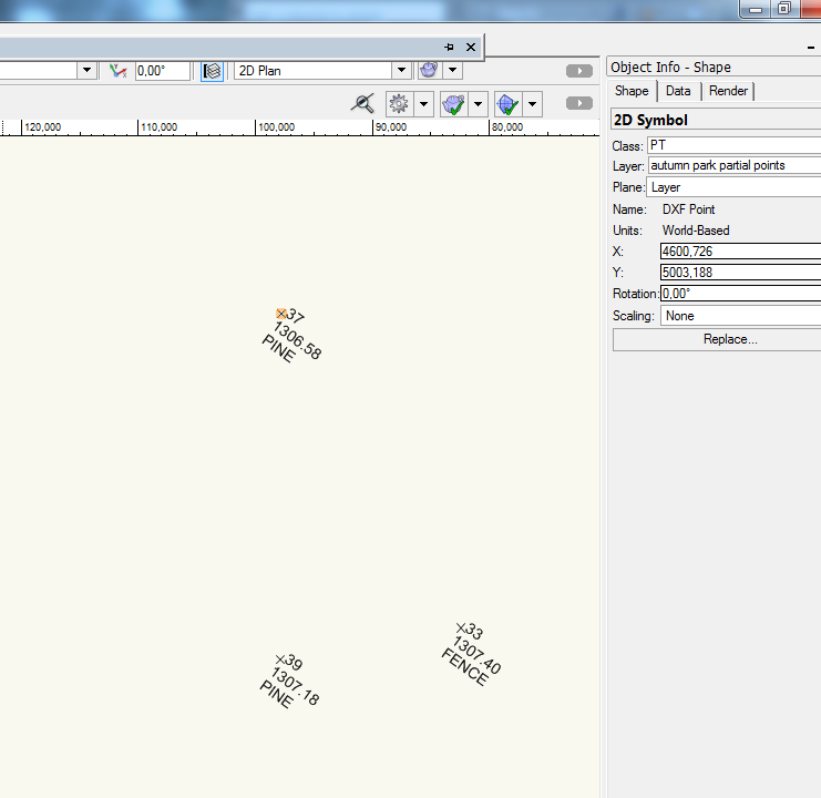
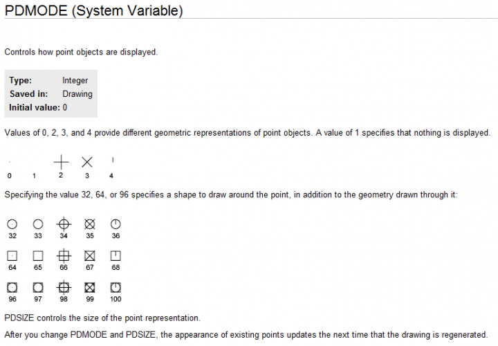
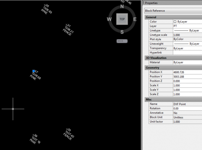
Coordinate data are available after the file is exported to DWG. Points are also created during the export, but they are not visible. You have loci inside the Vectorworks document, which are always exported as invisible points. In order to make the point visible inside AutoCAD, Acad users need to change the value of the system variable PDMODE. I am attaching a picture with the possible values. Alternatively, you might want to import the initial data from the DXF file using another import option for the points - use Import Points as Symbols. After import you could edit the symdef to adjust the "point" size or graphics. Then you can export to DWG and the Acad user will not need to do anything in order to see both coordinates and point location (points will be presented as Block References). Hope this helps, Nina


-
2018 SP2 CRASHES DURING DWG EXPORT
Nina Ivanova replied to Wesley Burrows's question in Known Issues
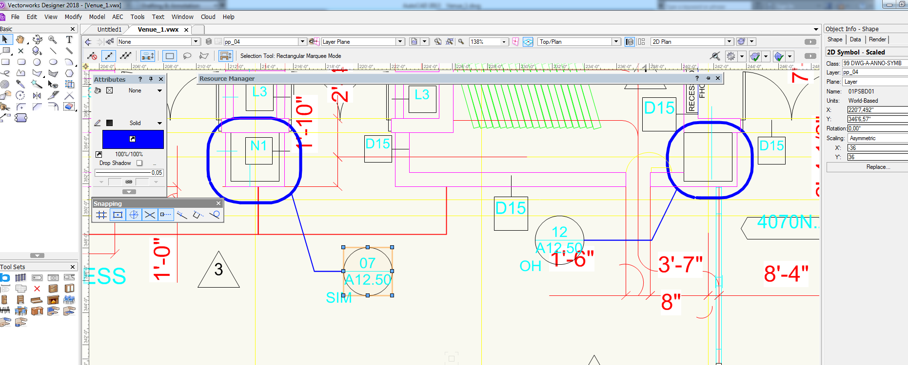
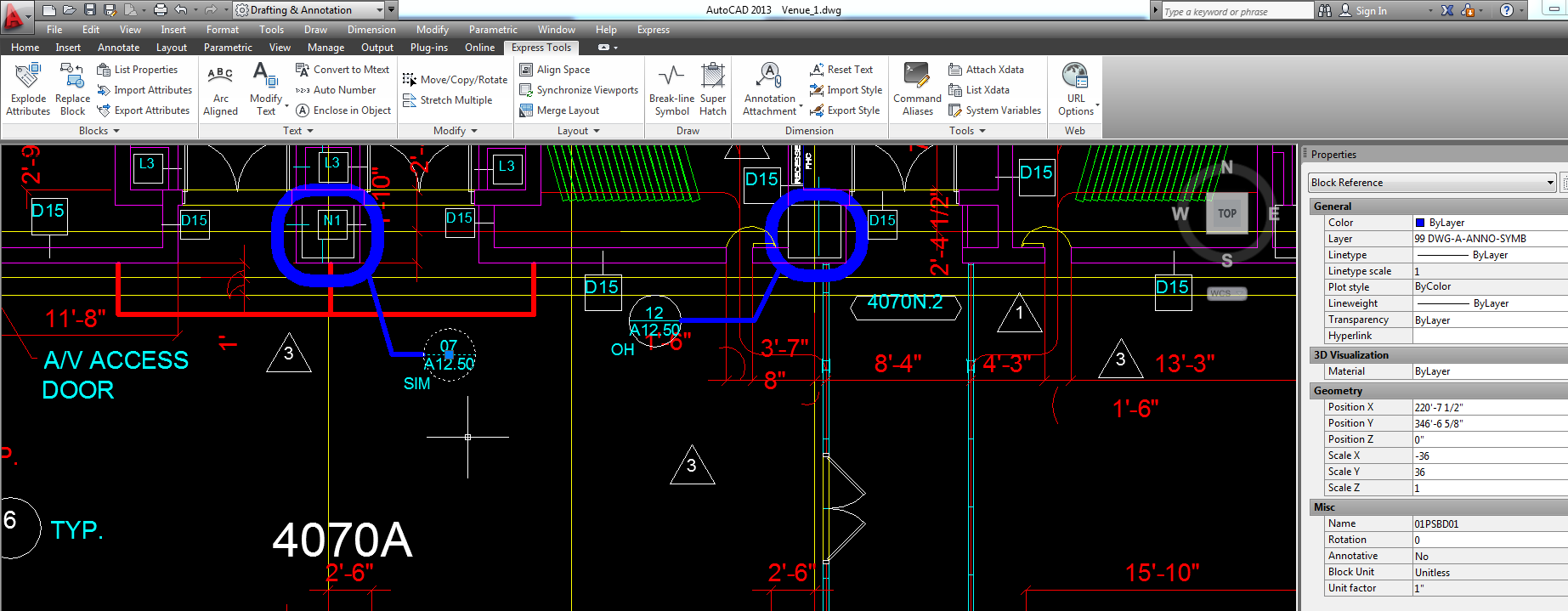
Thank you, Wesley! Yes, this is a known problem for SP2, which is already fixed for SP3. It appeared after some restrictions done in the third party library, which we use for reading and writing DWG files. We had to adapt our code to follow the same restrictions. This problem appeared in a very special case - export of negatively scaled symbol instances with attached to the symdef record format - which usually happens when you have an imported DWG. There are 3 such symbols in your document - 01PSBB01, 01PSBD01 and 01P054. Detaching record format from mentioned symdefs fixes the problem (and there is no loss of data after export to DWG - see images). Thank you for reporting and sorry for the inconvenience. Nina Venue_1.vwx

-
2018 SP2 CRASHES DURING DWG EXPORT
Nina Ivanova replied to Wesley Burrows's question in Known Issues
Hello Wesley, Would you, please, attach an example DWG so that we can investigate? Thank you, Nina -
I would say, that it is due to the difference in the CAD packages - there are things, which you can do in Vectorworks, but there is no exact way to export them in a DWG file.
-
Thank you for the images, Laura! Would you, please, attach an example Vectorworks document (.vwx file)? Thanks, Nina
-
Hello Laura, Would you, please, attach an example document, which shows your problem? Thank you, Nina
-
Why the DWGfile coordinates x'y are reversed
Nina Ivanova replied to Neko_Akatsuki's question in Troubleshooting
Pat, coordinates are reversed in the DWG file. There is nothing we can do on DWG import. -
Why the DWGfile coordinates x'y are reversed
Nina Ivanova replied to Neko_Akatsuki's question in Troubleshooting
And the updated DWG, which shows the reversed coordinates: LP-3.00-WCS.dwg -
Why the DWGfile coordinates x'y are reversed
Nina Ivanova replied to Neko_Akatsuki's question in Troubleshooting
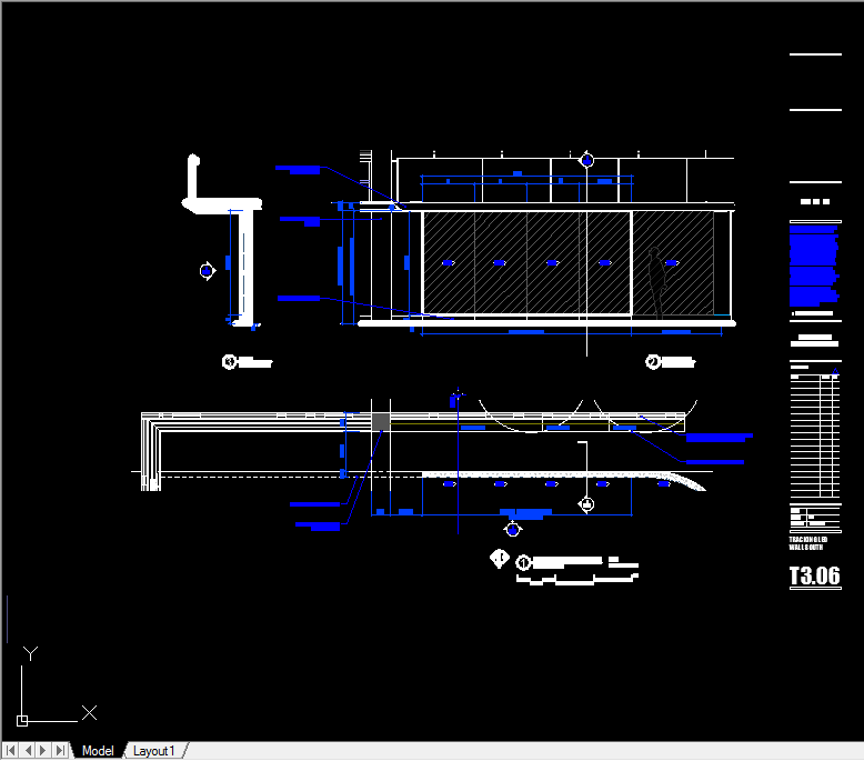
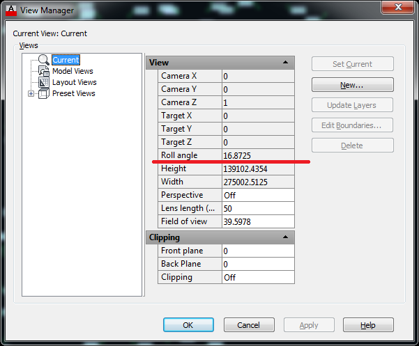
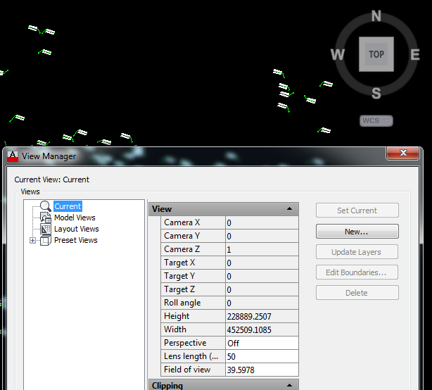
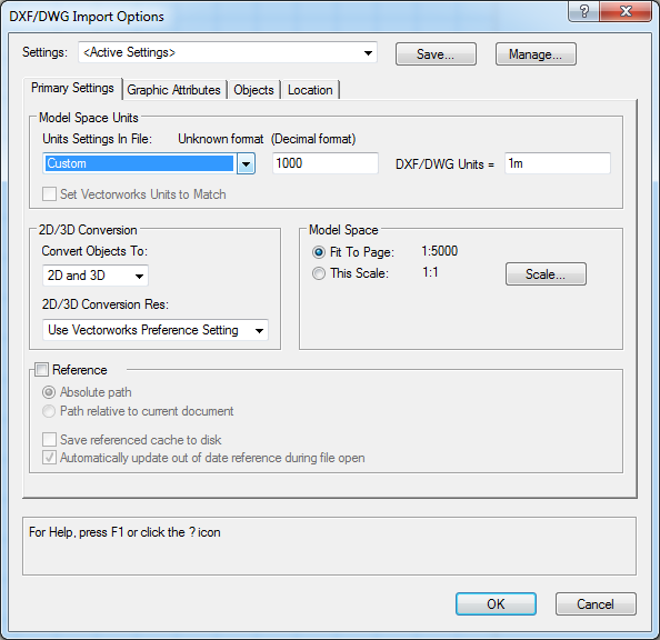
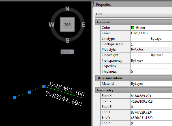
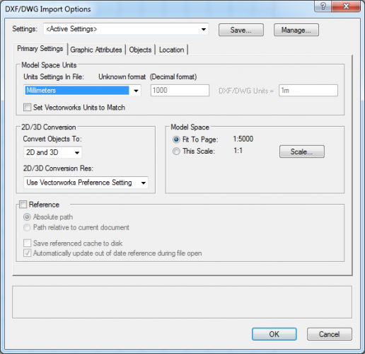
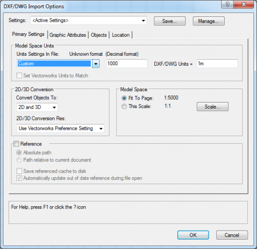
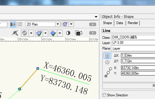
This DWG uses a custom coordinate system. Converting the UCS back to the World Coordinate System and changing the Plan to Current shows the coordinates in the way you see them after importing in Vectorworks. Original DWG Updated DWG (LP-3.00-WCS.dwg) and coordinates there DWG file is set to Unitless, so you have to ask the originator of the file what are the exact units there. As coordinates, reported by AutoCAD are 1000 times bigger then the X and Y text (except that they are switched), then during import in Vectorworks you will need to set that 1000 DXF/DWG Units are converted to 1 VW Unit. For example, if the X and Y text in the DWG refers meters, then set your VW document units to meters, and from the DXF/DWG Import Options dialog choose the Units settings as shown on one of the images: or Then you will receive the following: Hope this helps, Nina

-
DWG Import - Arc Position Not Correct
Nina Ivanova replied to MultipleWays's question in Troubleshooting
Hello btg, Would you, please, attach a DWG file which shows the problem? Thank you, Nina -
DWG Export - Extrudes
Nina Ivanova replied to zoomer's question in Wishlist - Feature and Content Requests
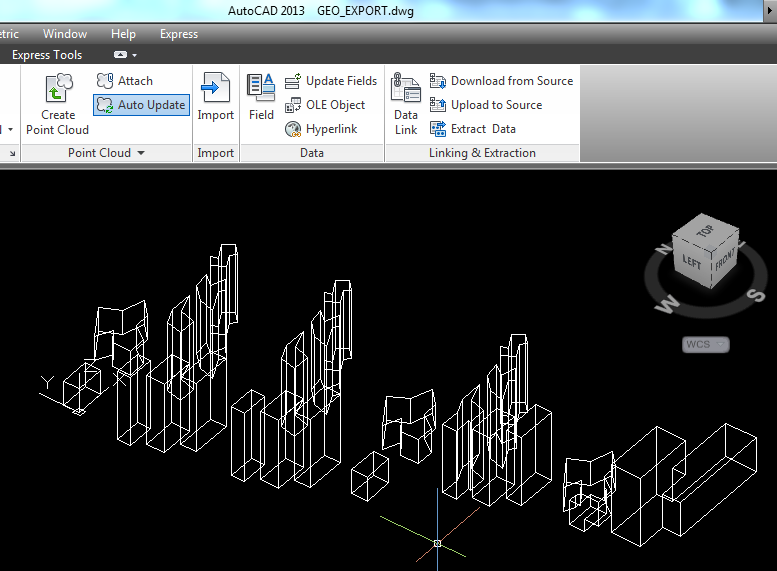
Hi Zoomer, Yes, the reason to receive faces instead of a single solid is that (most of ) your extrudes are defined by multiple profile objects - dark grey extrudes from Extrude Multi class, but also two of the generic solids from Solid Generic class and 1 of the solid additions from Solid Add from Solid class. For these single objects inside Vectorworks the ACIS/SAT third party library creator, which we use to generate the info for the DWG file, will return multiple objects - and if we pass such info to the DWG, it will not be accepted. Solid additions from solids and from extrudes, which have intersecting profile objects, are created as a single object by the ACIS/SAT creator and that is why they export as 3D solids. I do not see problems with 3D solid presentations inside AutoCAD - opening exported by me DWGs from both Mac and Win and even opening your attached DWG gives the result, shown on the image below. Probably the application, in which you are opening the files presents them in this way?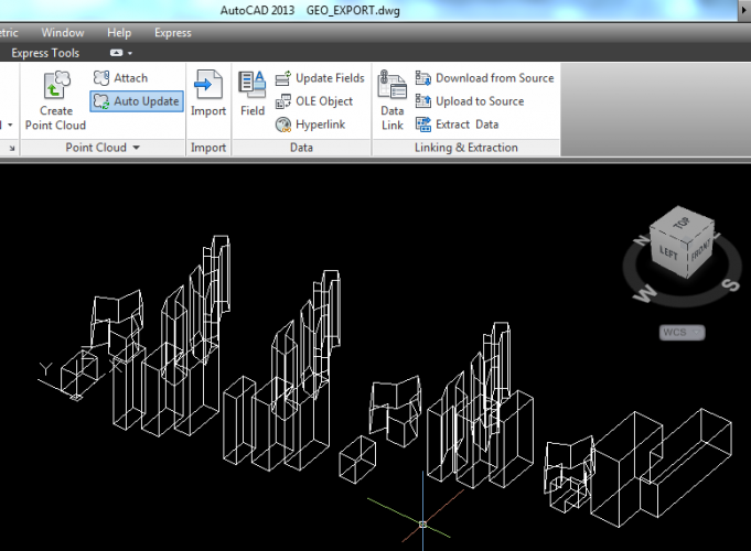
-
DWG Export - Extrudes
Nina Ivanova replied to zoomer's question in Wishlist - Feature and Content Requests
Zoomer, Do you have the option "Export Solids as ACIS Solids" set to ON? Extrudes do export as Solid objects to DWG if you have this option set to true. If you have the option set to ON and you still receive faces, then your extrudes might be defined by more than one profile object?