


markdd
-
Posts
3,413 -
Joined
-
Last visited
Content Type
Profiles
Forums
Events
Articles
Marionette
Store
Everything posted by markdd
-
If you want to make a custom door and frame then it might be better to start by building what you can with the door plug-in and when you have got as far as you can, then convert it to a group. (Because the plugin object is a hybrid tool you will loose either the 2D or 3D entity depending on what view you are looking at at the time you convert. If you want both the Top/Plan and the 3D entities then copy the plugin and convert twice from each view.) Thereafter you can edit and model as you wish. It will no longer be a plug-in object but you will have the basics set out that you can add to. Convert the finished door frame to a symbol. In order for the resulting symbol to sit within a wall object you will need to edit the symbol options (right click on a symbol in a resource browser). Check the Insert in Walls option and then experiment with the dropdown menu below to get the results you require. See how it works out and come back if you need any more info.
-
If you add a FRAME and set it to 0 values then it should give you a blanked out rear. Hope that works for you.
-
Are you trying to build the door opening, or the door leaf itself?
-
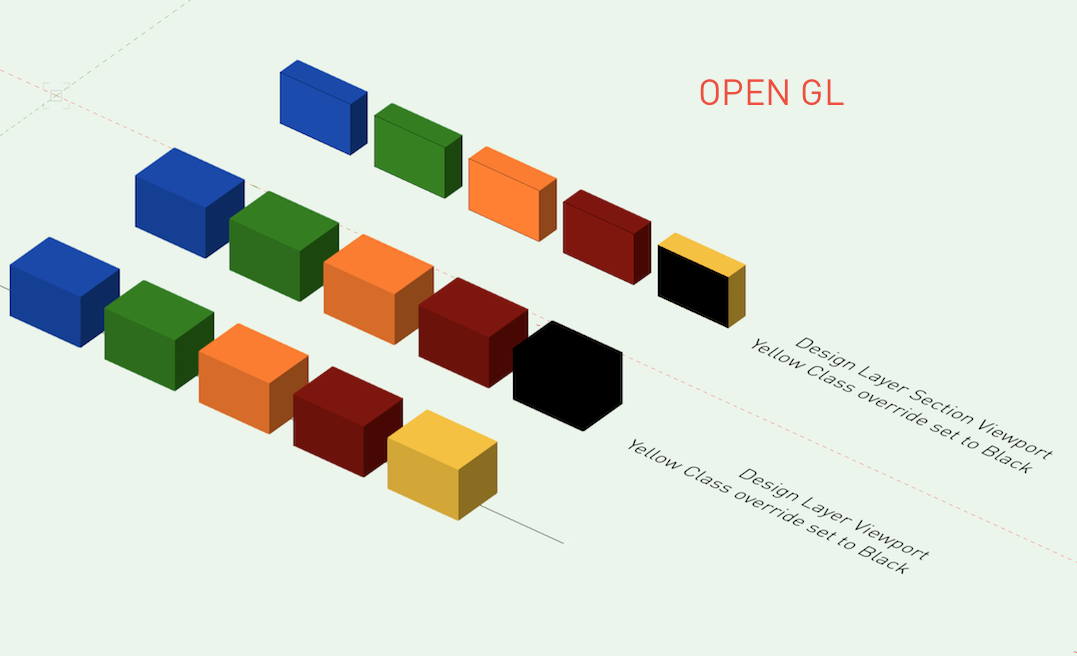
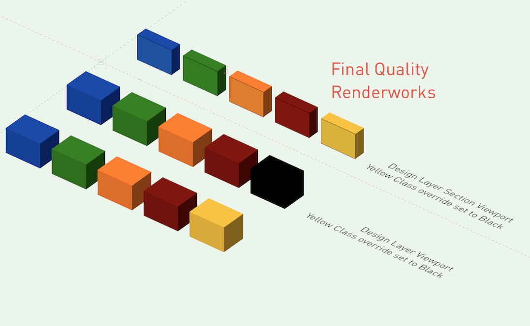
I have noticed a strange inconsistency with Section Viewports on design layers when rendered with different settings. Is this intended? I'll leave the pictures below to demonstrate the inconsistencies.

-
Class override not affecting instance of slab style
markdd replied to Josh NZ's topic in General Discussion
It seems you are right. Only the "New Slab" style seems to behave correctly. Or is that one behaving odd and the rest are behaving correctly? Frustrating. -
You can edit lighting positions. Double-click and if they have not been converted into symbols during the "Convert to Lighting Position" process, then you can edit the geometry as described above. If they have been converted to symbols, then just locate the symbol name in the OIP of the Lighting Position and edit in the way you would edit any other symbol.
-
In the OIP there is a field named Total Pipe Length. (This will be greyed out if you have anything other than a straight line) Otherwise, double-click it and reshape in the same way you would a polyline. That should do it. Mark
-
X 100
-
There is some new functionality in later version of Spotlight which means there is now a Spotlight Preferences Dialogue. You can find this under the edit tab ( I think, I'm away from the computer at the moment) Here you can adjust some class related parameters which may be causing unexpected results. (Just a thought) Also, try editing one of the instrument symbols. That might make a difference?
-
Make sure that your lighting pipe has double lines selected in the OIP (object info palette) . also make sure that the class settings for the object give the pipe a solid fill. you may also have the auto class functionality of the object set to something strange and the resulting classes are not displaying what you expect.
-
This doesn't directly answer your question but there is a button on the toolbar that toggles the preference. That might be the route of your problem.

-
Vectorworks: PC to MAC, MAC to PC
markdd replied to MRD Mark Ridgewell's topic in General Discussion
My experience with this is YES. -
Do you have environmental lighting enabled in your renderworks background?
-
Odd duplicate fixture issue with Design Layer Viewports
markdd replied to scottmoore's topic in Entertainment
Yes but not in a viewport. I have had instrument symbols ghosting inside other instrument symbols when editing. Reopening the drawing always sorts it out. Annoying but not disastrous!! The viewport issue is new to me though. -
Have you tried changing to a different workspace?
-
There was an earlier post about this and @Pat Stanford wrote a couple of short scripts that work well. I have changed the TRUE value to FALSE and it now hides all the objects that are not selected. I have made these into menu commands and added them to my object context menu and the SHOW ALL command to my document context menu. Works really well although you get some slightly weird behaviour within groups and symbols. Very useful though.
-
Alan, are you referring to animation using the Animation Works plug-in or is this all available with stand alone VectorWorks?
-
search functionality in Resource Manager
markdd replied to grant_PD's question in Wishlist - Feature and Content Requests
Click the little pull down arrow on the left of the search field. All will be revealed! -
Receive shadows is correct. Turn it on and it should stop beams going through solid objects. You will need to re render to see the effect although it looks to me from the photo that there is no light coming from the fixture which points to a further problem. Are you using a symbol that has shipped with VW Spotlight? Post the file if you like and I could take a look.
-
Make sure that you have "receive shadows" turned on in your Renderworks background
-
Some very rudimentary movement of items has been achieved using Marrionette nodes and @Alan Woodwell is probably the guy to ask about that. There is a video he made below. Vectorworks is primarily designed as a 2D/3D drafting and render programme and at this it excels. If you want to create scenic animations then you can export VW models to other software like Cinema4D which can handle this type of work. Good luck. It would be interesting to know what you discover. Of course if you just want static presentation slides or the ability to model positions of scenery, then VW will handle this with ease and setting up different scenes and positions of objects is easy using classes and saved views with any moving scenery pieces as separate symbols.
-
cycling through overlapping objects
markdd replied to wingchudesign's question in Wishlist - Feature and Content Requests
Does the "Select Coincidence" function not answer this need or do you mean something else? -
Viewports, sheet layers and export probs with scale.VW 17, Mac
markdd replied to Avellana's question in Troubleshooting
The greyed out rectangle is the size of the paper you are printing to. Go to File, Page Setup and uncheck page breaks. This is also where you can change the size of the paper you are printing on to. Once you have the correct paper size I find it is more useful to keep the paper size visible. With regard to your viewports, then it looks like you need to look at the design layer scale of the source objects or the scale of the viewports on the sheet layer. You should be able to adjust the scale of the viewport from the object info palette. Now you know what the grey rectangle represents, it might help you with making decisions about what scale you should be printing at. -
Rotate Tool - Alignment Mode I understand the principle behind this mode but at the moment can't really think of a real world use for it. The help section is vague and the video tip is very brief. Could the forum help me with a bit more of an explanation of this mode and more usefully give me a really good real world application. Many thanks
-
Does the "fix profile" option not do what you need?
