


Pat Stanford
-
Posts
12,675 -
Joined
-
Last visited
Content Type
Profiles
Forums
Events
Articles
Marionette
Store
Everything posted by Pat Stanford
-
How to calculate a worksheet limited to a viewport?
Pat Stanford replied to Charlot's topic in Entertainment
Unfortunately, no you can't have an object report what space it is in. The LOC command effectively checks each object in the drawing to see if the bounding box of the object matches with the boundary of the LOC object. There is no link between the LOC object and the other drawing object(s). LOC objects don't even have to be unique. They can overlap (or even be duplicates, but I can't think of a reason you would want that). You won't get a live link, but it would be possible to write a script that given a list of LOC objects would compare each object in the drawing to those LOCS and store the name of the LOC in a record. But the script would have to be rerun after changes are made or the information could be out of date. -
Do you realize you have both Row 2 and Row 3 set to be Database rows? I think you are editing Row 2 and then looking at the results in Row 3 the next time. Try going to the Worksheet View menu and selecting (Check) the Database Headers option. This should show you Row 2 and Row 3 (Not 2.1, 3.1, 3.2, etc.) Right click in the Row 3 header and select Edit Criteria for that row. It should stick. Right click in the Row 2 header and select Spreadsheet (instead of Database) for the row type and you should be set.
-
Add a text entry column to a worksheet?
Pat Stanford replied to Bruce Kieffer's topic in General Discussion
Sent back. Seems to be fixed but I don't know why. -
Layer('Staging)' Symbol('Table', 0, 0, 0); Where the third zero is the rotation. Layer('Lighting'); Symbol('Console', 0, 8' 6.5", 0); Move3DObj(LNewObj, 0, 0, 3'7.375"); I don't know how to make it a lighting device. Since there are no variables you should be OK to run the above as is. If you expand to need variables then you need all of the procedure statements and Begin/End functionality. Ask again for more help.
-
You can post anything you like in the Wishlist forum in terms of feature requests.
-
Add a text entry column to a worksheet?
Pat Stanford replied to Bruce Kieffer's topic in General Discussion
It all looks right. DM me the file and I will take a look. If the record is not attached it should just return blank. -
"Remove By Class Settings" file-wide
Pat Stanford replied to Andy Broomell's topic in General Discussion
I do have a life off of the forum you know. ;-) Yes scriptable. Probably not until tomorrow though. -
Added Lighting Devices - Default Off in existing Viewports?
Pat Stanford replied to MattG's topic in Entertainment
I can't figure out a way to have newly added lights to not automatically turn on in all viewports. Hopefully someone who follows me will see this and reply. -
VW2018 SP6 & Mojave - text & OIP bug
Pat Stanford replied to Kieran ROA's question in Troubleshooting
@JuanP Has tech support seen any other reports of slow text in VW2018? -
Reassign classes within (multiple) symbol definitions
Pat Stanford replied to Marc Davies's topic in Architecture
Do you want all text in the entire drawing to be in the "text" class? This would be a pretty easy script. Especially if you follow best practice and always import into a blank file before moving the data into your active drawing. -
Can you post the file please?
-
I don't know if anyone still finds it useful or not, but it was originally designed for architectural setting up of layers. Ground floor layer z of zero and layer height of 2500. Create next layer for second floor you get automatic , Layer Z of 2500 + Layer Height of 2500, New layer for 3rd floor automatic Layer Z of 5000 and Layer Height of 2500, etc. But even for architecture this was too limiting. Which is why Stories were added so that when things need to change you can adjust the story height and have items that are bound to the Story levels automatically adjust. Perhaps temporarily reset your layer to a level of zero and a layer height of zero, Create your new layers, then reset the heights to what you want. Best solution I have right now. Plus, check the Edit Properties After Creation box for layers so at least you will see and have the option to change the values if they are wrong. Update, the layer Z increase only occurs if you create a New layer. I you Duplicate a layer it will take the values of the layer. So create a "template" layer with layers of zero and duplicate that instead of creating a New layer. And when you do it wrong, the following one line script will reset the layer height and layer Z of the active layer to zero. SetLayerElevation(ActLayer, 0,0); Copy and paste the line above into a new blank script.
-
Unfortunately that is the functionality. Each new layer is created at the Z elevation of the previously created layer(s) plus the Layer Height of the previous layer. So if you create a layer at 5000 with a layer height of 2500 the next layer should have a z-height of 7500. Manually editing them is the only work around I know. :-( Hopefully someone will prove me wrong.
-
Exactly what tool and settings are you using to draw the fasteners? What fasteners? What scale are you drawing at? I have not had any problem in drawing fasteners in VW2021.
-
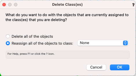
Once you have one version of the class with the correct name, just delete the other classes that should use that name. You will be presented with a dialog box asking what you want to do with the objects in that class. Just reassign them to the proper class.
- 1 reply
-
- 1
-

-
Add a text entry column to a worksheet?
Pat Stanford replied to Bruce Kieffer's topic in General Discussion
Yes and No. Since Worksheets are dynamic, you can't just enter data into a cell. It has to have somewhere to reside that is linked to the object showing in the subrow. This place can be either a PIO field (Doors/windows/etc. have UsrFields that can work for this) or it can be a field in a custom record. If you only need a single field it will be a simple single field record. In Resource Manager create a new Record Format. For convenience in this decription I am naming the record "MyRecord". You can use any name you want. For the Record Edit window add a New Field named ID (or anything you want) and give it a type of Text. I normally use a blank default, but if you want all of your parts to have an ID you can put in anything you want. My company uses 99999 for non stock parts. In the worksheet the formula you want is: ='MyRecord'.'ID' Attach the MyRecord record to all of the parts in the Data pane of the OIP. Now anything you type into the ID column of the worksheet should be attached to the part. If you edit the ID in the OIP the worksheet will update. If you edit the ID in the worksheet the OIP will update. HTH. -
Worksheet data for thickness, width, length?
Pat Stanford replied to Bruce Kieffer's topic in General Discussion
Great! If that works for you then we are set. If you need to be able to select on a per part basis, it would not take much to do the Record check as part of the script. Let me know if you would like or need that. -
Under Truss Analysis section of the VS Function Reference did you look at: HP_ConvertToHangPosTruss Analysis Vectorworks 2019 VectorScript Declaration: PROCEDURE HP_ConvertToHangPos ; Python: def vs.HP_ConvertToHangPos(): return None Description: Invkoes the Convert To Hanging Position menu command on the systems of the selected objects.
-
Worksheet data for thickness, width, length?
Pat Stanford replied to Bruce Kieffer's topic in General Discussion
No good way for the script to know that the fields should be reversed. It would have to be something your manually added to the object. The simplest solution would be to add a Record to the objects that you want width/length reversed. The script could then check and see if that record exists (or we could get fancy and use and specific Field value in the record) and swap the fields if it does. Workflow would be something like draw the object, go to the data pane and attach the record. If you decide you don't want the grain running that way, then just unattach the record. Does this sound like a solution? -
Updating all Worksheets in a file
Pat Stanford replied to JRA-Vectorworks-CAD's question in Troubleshooting
Now that you have it as a Menu command you should be able to add it to the contextual menu also. -
Spacebar acting as an OIP 'undo'
Pat Stanford replied to hollister design Studio's topic in General Discussion
One of the problems that happen in so many programs that currently overload the space bar with so many functions. -
Updating all Worksheets in a file
Pat Stanford replied to JRA-Vectorworks-CAD's question in Troubleshooting
What no keyboard shortcut!!!! All that work and you don't even think enough to give it a shortcut. Humph! ;-) -
Can you get a much simpler PDF exported from VW and see if that imports for you. If it does, then we can move to the next step in figuring out how to get the big PDF to work. If it does not then we have a different problem to diagnose. Do you know anyone who is using Indesign that you could have test the PDF and see if it imports for them?
-
If you are duplicating the Worksheet Image on the drawing, you are not duplicating the worksheet. Try duplicating the worksheet in the Resource Manager and then putting an image of that worksheet on the drawing. That should get you two separate worksheets that you can individually set the criteria for. If you are putting both images on the same Design Layer or Sheet Layer, you can just put a second database into the same worksheet as another possibility.
-
Screen Plane difficulties
Pat Stanford replied to hollister design Studio's question in Troubleshooting
The following is my own personal recollections and opinions. They have nothing to do with my role as a volunteer moderator on the forums. Nor do they in any way respresent opinions or policies of VW. Screen Plane exists because in many industries, specifically architecture and entertainment lighting, it is typical or required for objects to show differently in a Plan view than in a a 3D view. Think about a Door where you want a simplified version showing the swing in Plan while you want the full version showing all of the glazing, etc. in the model. These function area essential to entertainment lighting design and landscape architecture (plant) aspects of VW. Originally Vectorworks (Minicad) started with the idea of "hybrid symbols" In these any 2D objects showed in Top/Plan view and any 3D objects showed in all other views. Over the decades, this has morphed into the more complicated but more capable system that we have today. Eventually it was decided that there was a need to 2D functionality that was not fixed to the screen plane. This resulted in the addition of Layer Plane and Working Plane Object. So you can now specify what "plane" you want a 2D object (line, rectangle, dimension, circle, arc, etc.) to be on. In a hybrid object (mostly symbols and PIOs), anything that is defined as a Screen Plane object will display when you are in Top/Plan view. Objects that are in other planes will show in all other views. If you have an object that has ONLY object that are not Screen Plane (3D symbols for example), then the 3D objects will show in Top/Plan as well as in other views. Similarly, an object that has ONLY Screen Plane objects will show in 3D views as well as Top/Plan. Somewhat recently (2018/2019?) Symbols (and maybe PIOs) have been updated with the ability to use "2D Components" for the Orthogonal views. These are similar to the old show Screen Plane object when in Top/Plan, but only show the 2D in the 6 primary othogonal views and only in Hidden Line rendered viewports. This gives you more flexibility in Plan and Elevation to produce drawings that contain the appropriate (maybe more, maybe less) than the 3D model does. So back to your question. If your workflow does not require the use of the differential view for Top/Plan, it is perfectly acceptable to make all 2D objects to Layer Plane or Working plane. Just remember that you (and by you I mean pretty much every individual reading this post and/or using VW) uses it in a different fashion. Things that you might think are useless are critical to some other groups primary workflow. Please don't ask for things to be taken away just because you don't use them. These functions being present and getting VW a bigger install base helps keep the underlaying layers of code moving forward and makes it a better program for everyone. Four items that separate VW from other drawing software are the worksheet, Vectorscript/Pythonscript customization, stackable layers/classes, and the Hybrid view Top/Plan functionality. IMNSHO, without these items, VW becomes not much more than an on-screen drawing board. With these, you get a highly flexible, integrated system that can provide great value. At the expense of having a steeper learning curve. Your mileage may vary. Now back to our regularly schedule programming. Pat
