Gadzooks
-
Posts
509 -
Joined
-
Last visited
Content Type
Profiles
Forums
Events
Articles
Marionette
Store
Everything posted by Gadzooks
-
The shortcuts are all listed here http://app-help.vectorworks.net/2018/eng/index.htm#t=VW2018_Guide%2FVWKeyboardShortcuts%2FVectorworks_2018_Keyboard_Shortcuts.htm
-

Can't select objects created in a layer
Gadzooks replied to justinekwood's question in Troubleshooting
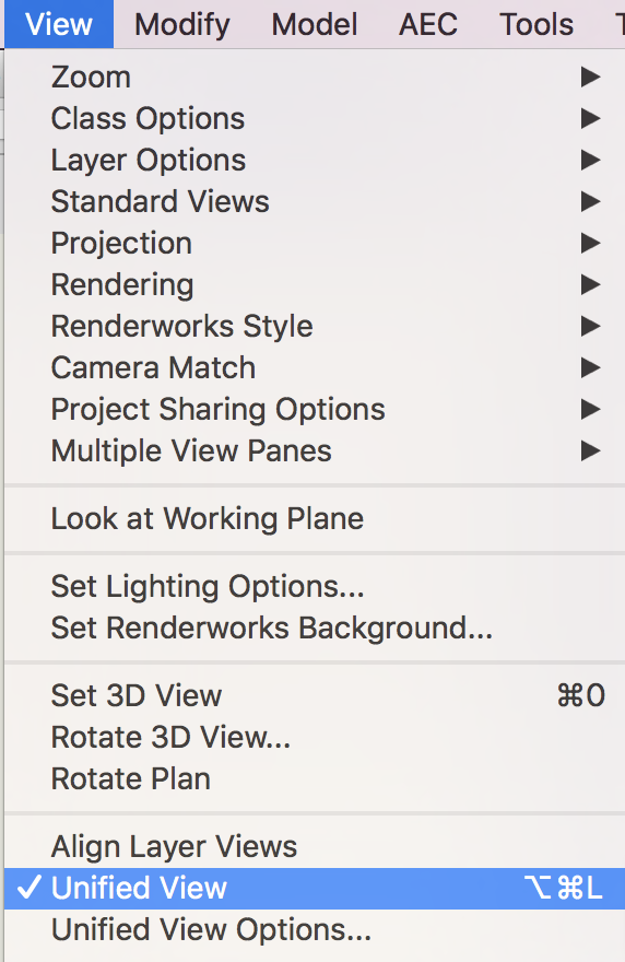
Seems odd after you had earlier said that class visibilities had been the cause. Whats changed? However if it's still a problem, I thought this would be something quite simple, but it seems not. I'm not aware of any other factors that would affect the drawing like this. Someone else may be better informed. Other than that - are you able to post the drawing, or part that still shows problems? I'm happy to have a look at the file if you PM it to me. EDIT Grasping at straws here - I think you most probably have, but just to confirm - you have Unified View on?
-
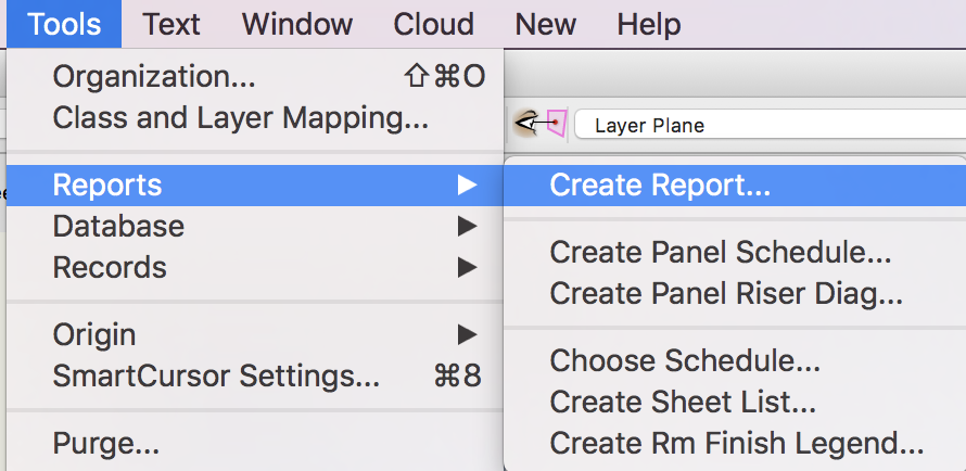
Always worth searching for VW's excellent tutorials when you need some advice - good reference from @Diego-Resuelvectorworks You are using 2018 so you will see the worksheets are slightly different from the information (2017) in the vid. Many of the vids on line are still valuable resource even if they are a few years old. You will see familiar ways to create solutions. With 2018 you can also start the process by choosing one of the inbuilt Reports Have a look at some of the options - this can provide the basic setup and presentation, and after that you'll have to tweak it suit your own requirements.
-
Do you mean this?
- 1 reply
-
- 1
-

-
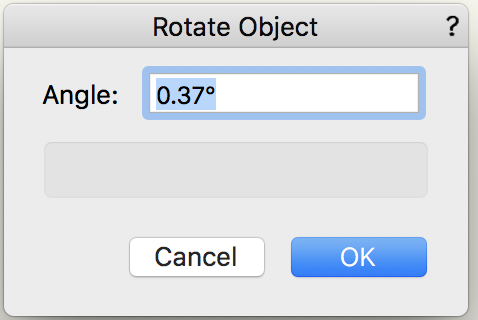
Don't copy - make it your own!! Your notation will say what it is. Unless the intention is to use a prescribed 'standard' hatches, use a hatch or perhaps a tile pattern that conveys the material. EG theres a standard tile for solid insulation already in VW. You might want to use? Well you have two problems actually - by the looks of it the two sections should be the same height as they are through the same wall but at different points. You might want to draw the left hand one first and then use 'construction lines' to piece the right hand one together. Or you can duplicate and go for resizing the scan again on that layer. I'd go for the first option as they must be the same. As for the rotation - I don't think theres much in it, but I make the required rotation 0.37º (anti) Use Modify > Rotate But really the scan is poor (thats why someone wants it redrawing!!) and theres probably other areas that are now sightly off. What do they say? - you can't polish **** (no doubt you know the phrase.) Hope this helps - lets see the finished section.

-
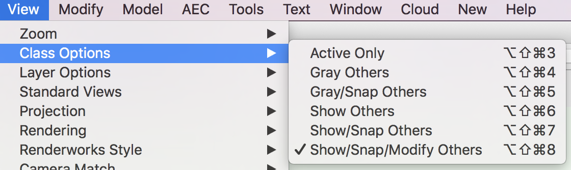
Ahh - don't you just hate being asked to "quickly draw this up.." The assumption being that all the work is there for you and it'll only take 5mins! This is 2D work - I don't think you should be contemplating 'walls'. Keep it simple drafting, using lines and areas of hatched solids to denote the materials used. Then add clean notation. So... The PDF looks like a poor scan. You could skew the drawing to a correct vertical, but probably more work than necessary - its near enough. I think I would first make sure the pdf had a relative scale that suits your work. Use Scale Object - Symmetric By Distance (using one of the given dims - the bigger reference distance the better the result will be) to remedy the overall 'look'. At least is is now a reasonable reference image. Then start drawing on a new layer above using a mix of the given dims and some deft scaling you should be able to reproduce fairly quickly. Don't have layers set to Show/Snap/Modify. Just Show should suffice. Turning off the image by layer visibility will offer a 'clean' peek at your work as it proceeds. Timer starts ......................NOW Hope that helps.
-
👍👍👍👍👍👍👍👍👍👍👍👍
-
Probably best to thoroughly understand the ways textures can be applied to the various wall surfaces, as VW offers a reasonable degree of customisation. There are several vids on 'the tube' - Try https://www.youtube.com/watch?v=d_VJkYTVf00 It may suit you better to use wall styles with the textures already applied, but for the moment if you have one wall you are happy with use the Eyedropper Tool (Shift-E) to pick the attributes from the 'correct' wall (The tool settings left as 'all attributes' will probably work fine for you). Now change the eyedropper to the 'apply attributes' mode and pick the various walls that aren't correct for you. You should now have all walls with the texture applied to just the one face. Come back if you have problems.
-
Can't select objects created in a layer
Gadzooks replied to justinekwood's question in Troubleshooting
We've all been there. HTH -
Can't select objects created in a layer
Gadzooks replied to justinekwood's question in Troubleshooting
Hi @justinekwood Looks like you have checked layer visibilities, but have you checked classes? Does the chair/table combo have a class of its own?
-
Hi @vicsrc I don't use the Océ, but first off, I think most would ask whether you have the latest drivers etc. and what your system is (add it as a signature). If you don't already have this - https://files.lfpp.csa.canon.com/media/Assets/PDFs/TSS/external/TDS400/TDS400_UM_XPe_US_v1_m56577569830529523.pdf
-
What effect are you after bc?
-
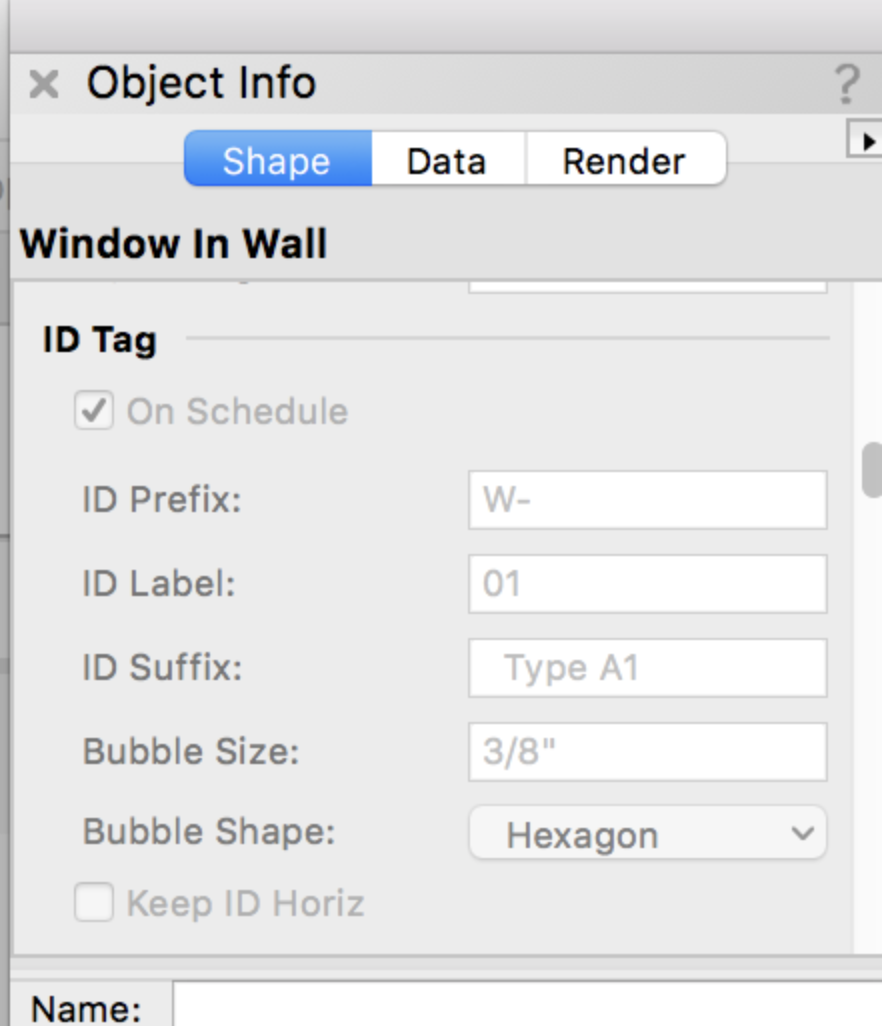
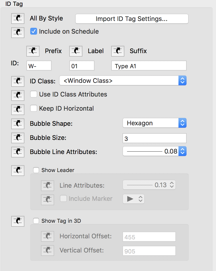
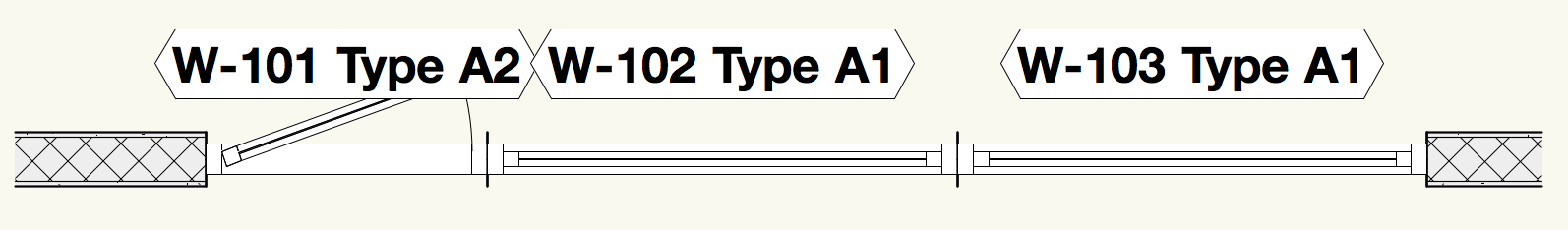
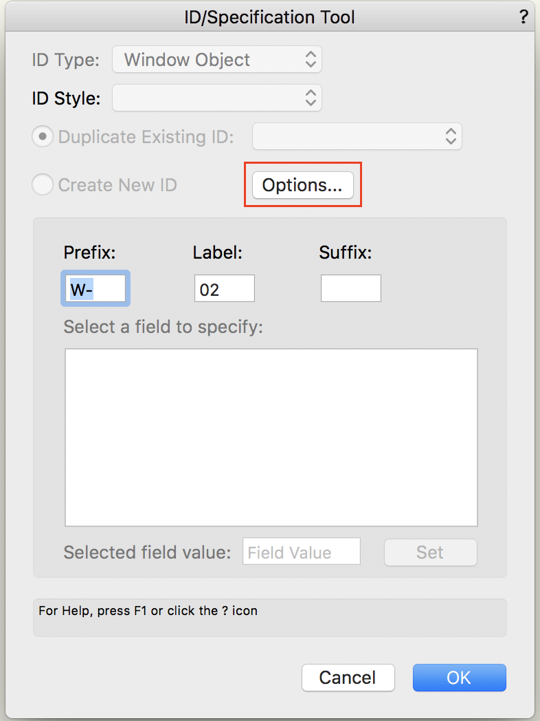
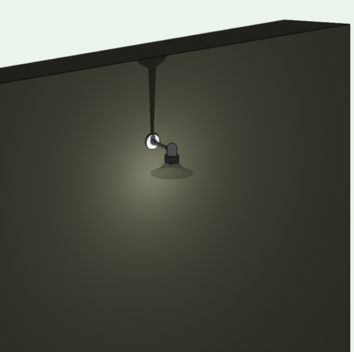
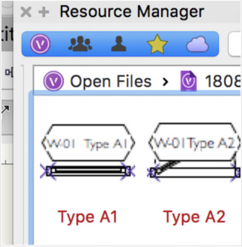
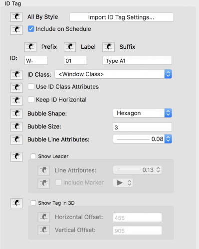
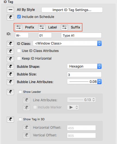
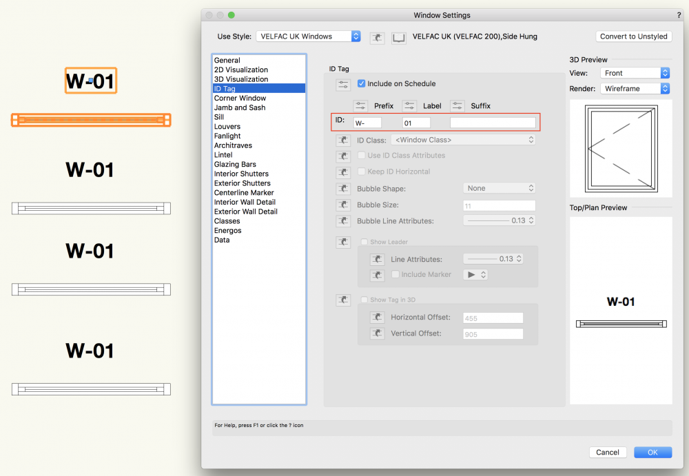
Yes - the window tool is fairly comprehensive in the options available, but can provide what you want. Your Resource Manager shows you have created two window resources for the project. These are your own custom 'Window Styles'. When you place them into the project, you create 'instances' of those styles. If you make direct changes to those instances (where available (see below)) you will not change or effect the basic Style shown in the RM. Alternatively, if (say) all Type A1 need to be wider, you will Edit the Style within the Resource Manager. This will then be reflected in all the instances (depending on some options) where that Style is in place. You say the option to alter ID Tag information is not available within the OIP. Your screen cap confirms. This is because the (Type A1) Style has been saved with ID Tag options set as 'Class' (set to be not editable) If you go back into the window Style you've created you'll see... (something like) If you click the 'by class' icons you will see the 'user options available' icon now shows. Here I've set the ID Tag options 'open'.. This will then be saved with parts available to edit. However, that was a bit of a side issue and you do not need to make this change to accomplish what you need. Using the ID Label tool will allow you to make the changes you need to the Label (including to those seemingly not editable by way of the OIP) Use the tool to click the windows and alter the settings (including Automatic increment) as you wish. I've placed three windows as you have... They are all 'raw' (showing basic Style info) and will need to be corrected with the ID Label tool. Using the tool I've given each window the unique numbering you wanted, including (say) adding a forward '1' to show these windows are on the first floor. A 'top tip' is to number windows anti-clockwise on plan. You will then have 'nicer' elevations with windows reading left to right (obviously tags need be set to show in 3D) I hope that works for you. Bit rushed - someone will correct me if I've missed something or shown steps incorrectly.


-
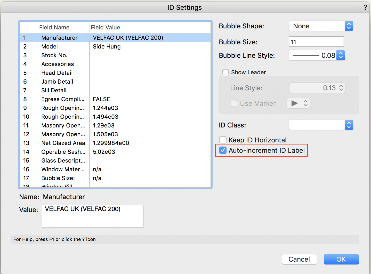
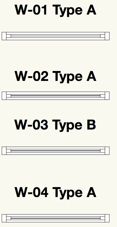
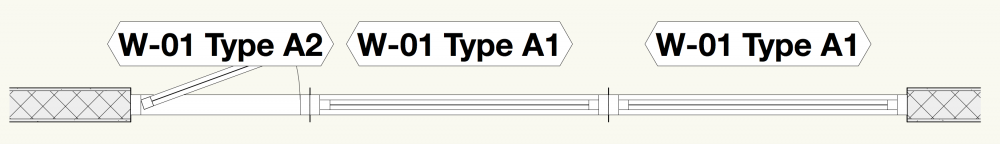
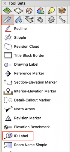
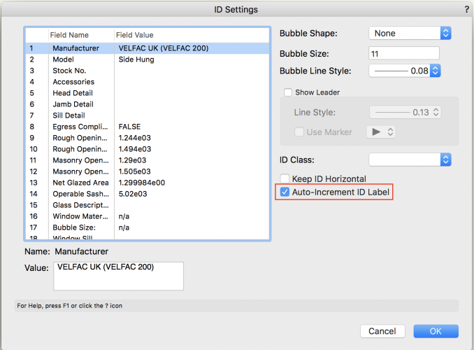
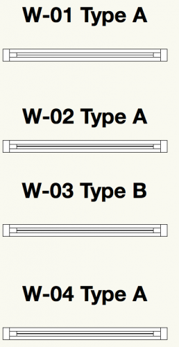
By your reference you seem to be using the ID Tag for windows and the default setting for the ID has provided you with W-01. The Include on Schedule checkbox allows the ID to show on drawings (theres a further option to show in 3D) You've then maybe duplicated the window and you now have a few of 'the same' windows on the drawing? If you use the ID Tag settings to expand on the information, you can change the label (number) appropriately. You might like to add a suffix - say Type A, or anything that suits your schedule/strategy. Similar options are available from the ID Label tool, but with further automation. and clicking on one of your windows with the tool will offer similar data settings for the window. Choose Options and then Auto-Increment from the resulting window. Further clicks on the remaining windows will now add as you go. And I've added a suffix. Good idea to have a play with the options you need and how they will fit in with any Window Schedule you create for the project, as a schedule will report any additional data you require. Let me know if I've gone 'off-piste' with this answer.

-
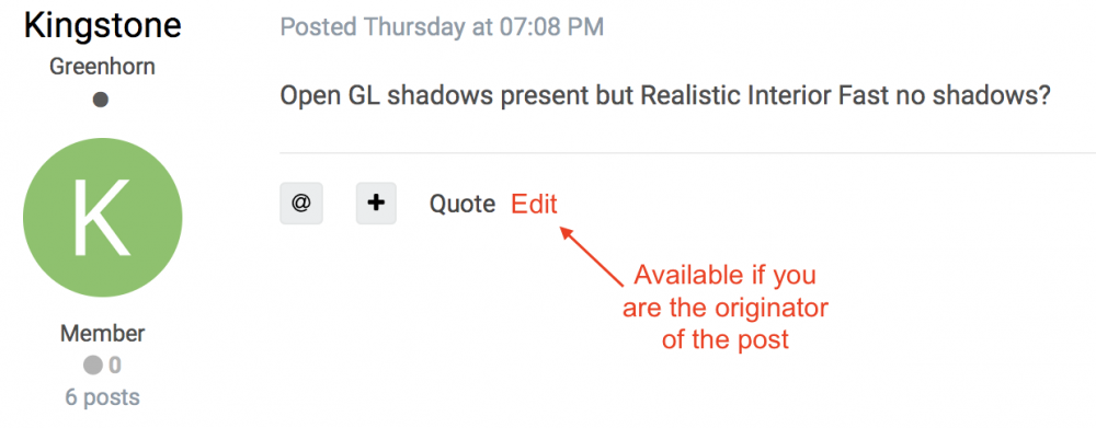
Help for next time..
-
The file you downloaded has no data. Opening in a text editor shows only.. Maybe download again?

-
😂
-
Choose to show a threshold and adjust it to suit the door opening. It will default to a white box with a border, but you can alter the 'class' settings to rid the box of its border.
-
Thought that was what you required. If you need the functionality of the door tool but only in 2D just keep to Top/Plan. But, I'd advise you start to use walls (still in Top/Plan) to really ramp up your workflow. (I'm trying to get you down off the roof of that car😀)
-
I'm intrigued @RDS Casa.. It seems you want to show insulation and then you seem to have turned to wanting to have studwork also. Why are you wanting to devise a method of having the studwork drawn which (by your own admission) is not really that 'accurate' and doesn't work very well in walls? Why aren't you using the framing tool? This will provide you with a really very good 'design intent' 2D plan of the stud layout(s). Also 3D framing panels if you wish - but it seems maybe the contractors only need an 'indicative' from you.
-
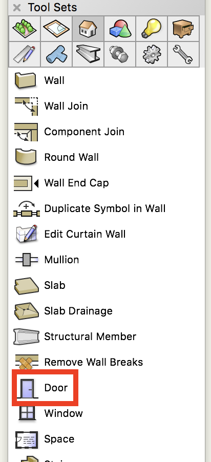
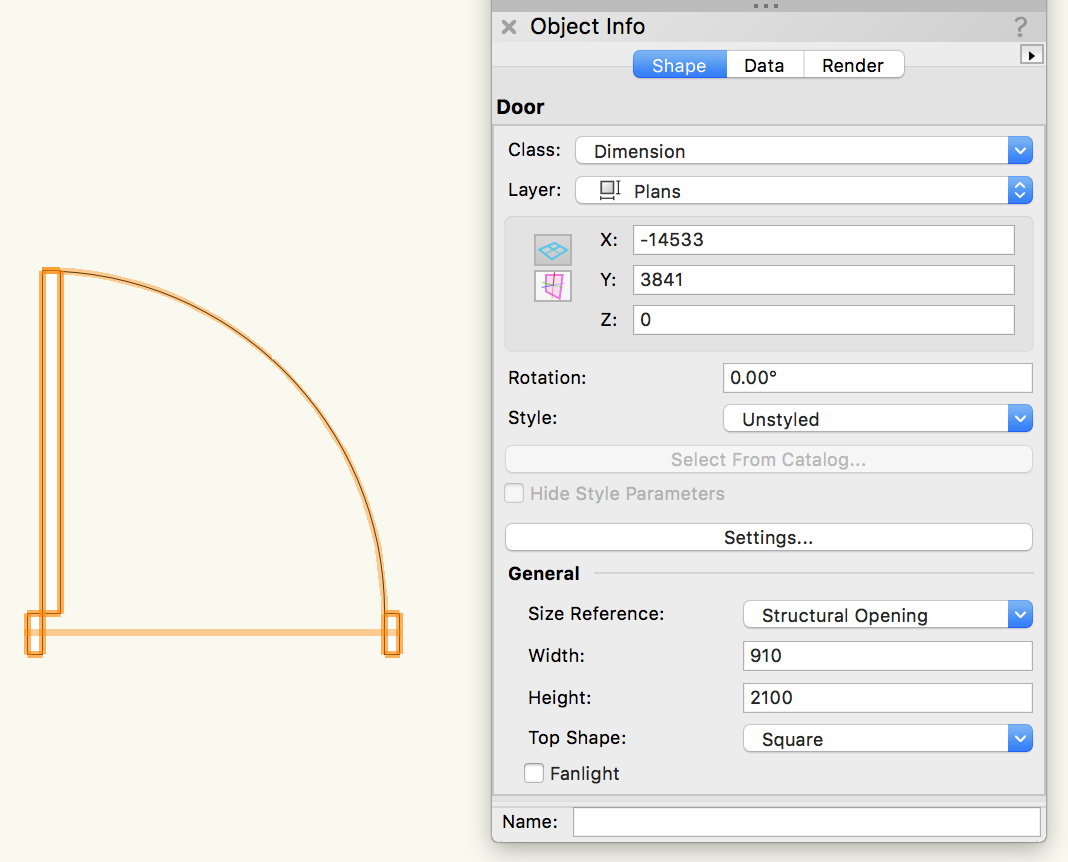
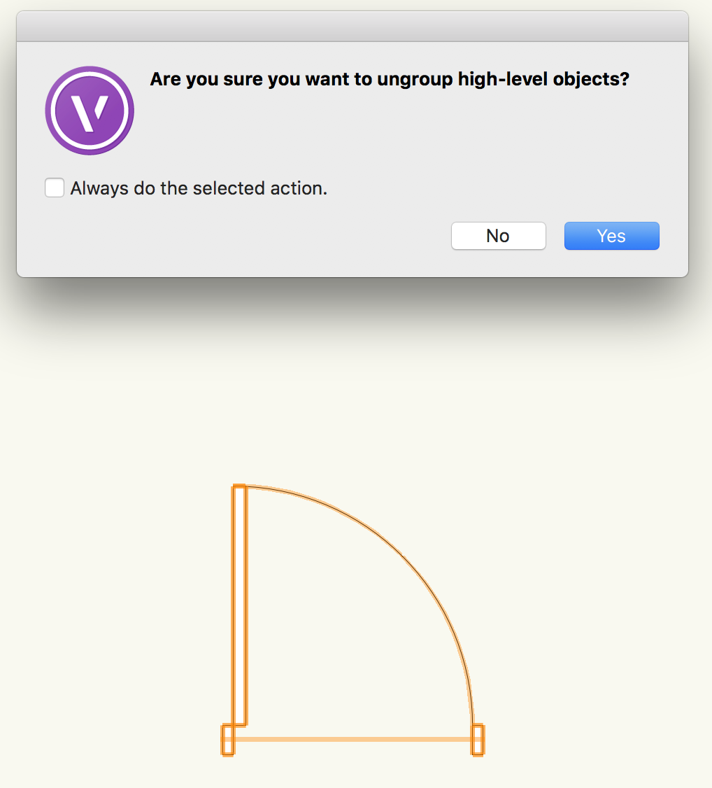
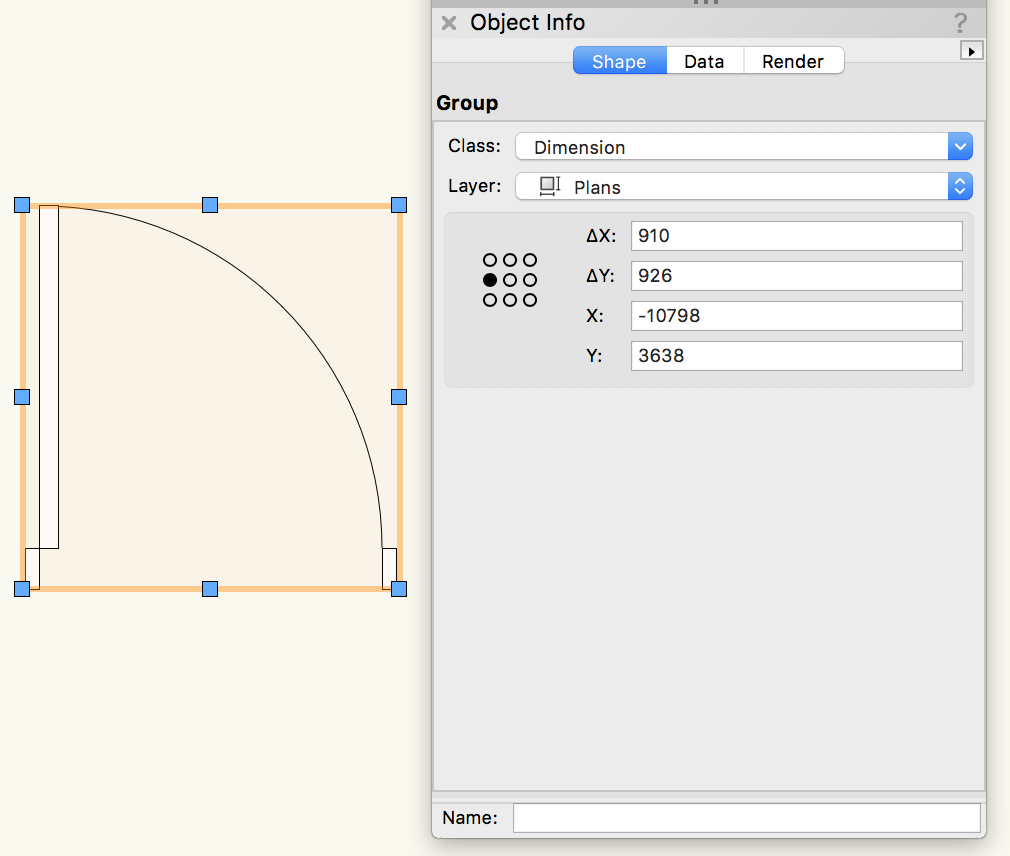
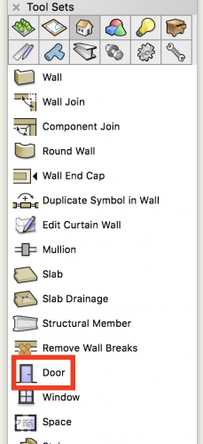
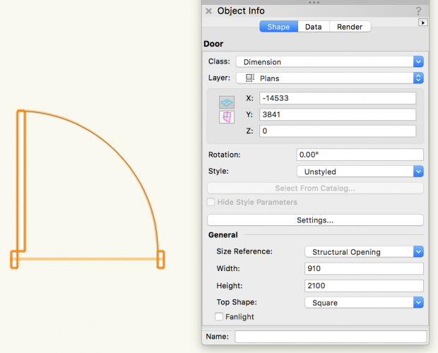
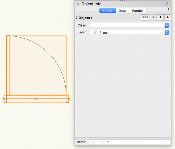
@jah011 (why, why, why????) (Not to be rude 😀) OK - seems you're in a position you're not able to influence. The company bought a new car with some excellent 'bells and whistles', but they insist you can only use it if you tether up a horse, sit on the roof and get pulled around town. To be serious, you have the tools available to stay with 2D if you need to. Choose door from the tools.. Place a simple 'unstyled' door in 'Top/Plan', and this will be placed in its 2D guise. You can see the OIP will allow you to change the simple width - which I assume is all you feel you need for this process. You can see if you go to a 3D view that the door is still capable of appearing in 3D. But I guess you need to 'kill' that. Pick the door shape and 'ungroup' OK to this.. The door now has its individual shapes (and lost the ability to show in 3D) Add your white polygon if you wish. Best to Group it again. You can now place this in your plans as your 2D only door. I assume you may choose this method for your windows? Suggest you create this into a symbol (maybe with the door width in the name) and use that, with other width doors, as your quick access door library. After you get used to this process, you could look at showing a door leaf half open etc. sliding/folding etc. (all with the 3D 'turned off') But really - you could be doing some 3D work on your own and showing your colleagues what a missed opportunity they have. (lost cause?) Hope the latter is something you try...and let us know! All the best. @Jim Wilson - why does the image above, that I deleted, still show?. Forum software bug?


-
(Goes without saying, but for those that don't know) You can always return the full roof by using the same 2D procedure with 'add surface' and then maybe an altered 'clip' shape if the building changes. Nice building btw.
-
You could look up the product sales/technical pdf's to check dimensions.
-
Yes - but sometimes Faces is what is easier to design with so the inconsistency in the controls is a disappointment. This has been raised with the boffins earlier. HTH - don't forget @Diego-Resuelvectorworks
- 8 replies
-
- 1
-
-
- roof
- components
- (and 2 more)
-
Agreed - hence my Edit of that post. This is a complication Roof Faces just can't deal with. Read on and use Roof rather than faces. (As discussed) this should work for you.