Gadzooks
-
Posts
509 -
Joined
-
Last visited
Content Type
Profiles
Forums
Events
Articles
Marionette
Store
Everything posted by Gadzooks
-
Yes Alan, but that doesn't provide the stop end detail required to the upper wall which I assumed RJR was after.
-

copying text (numbers) with increments
Gadzooks replied to JOE DE VILLIERS's topic in General Discussion
Sounds a good idea. This looks like a simple job for one of our marionette wizards. (Don't look at me!) -
In the preview options you have object size set to 0" atm When you try to leave it highlights the zero waiting for a change.
-
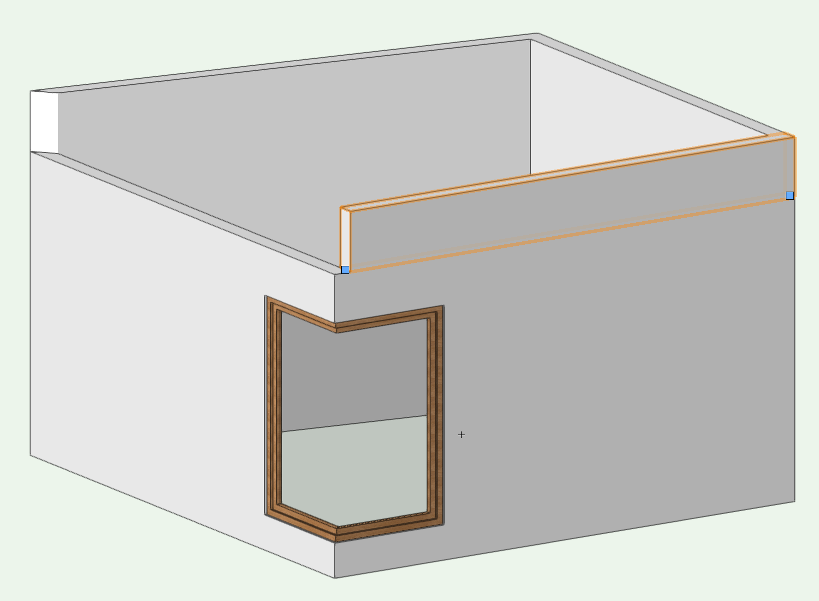
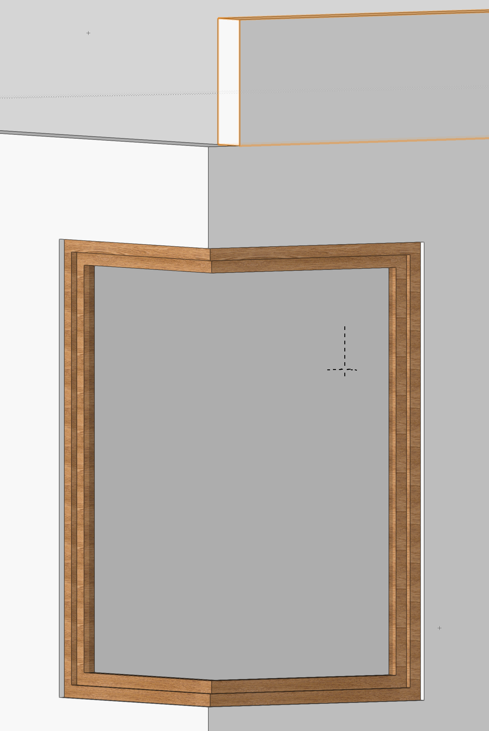
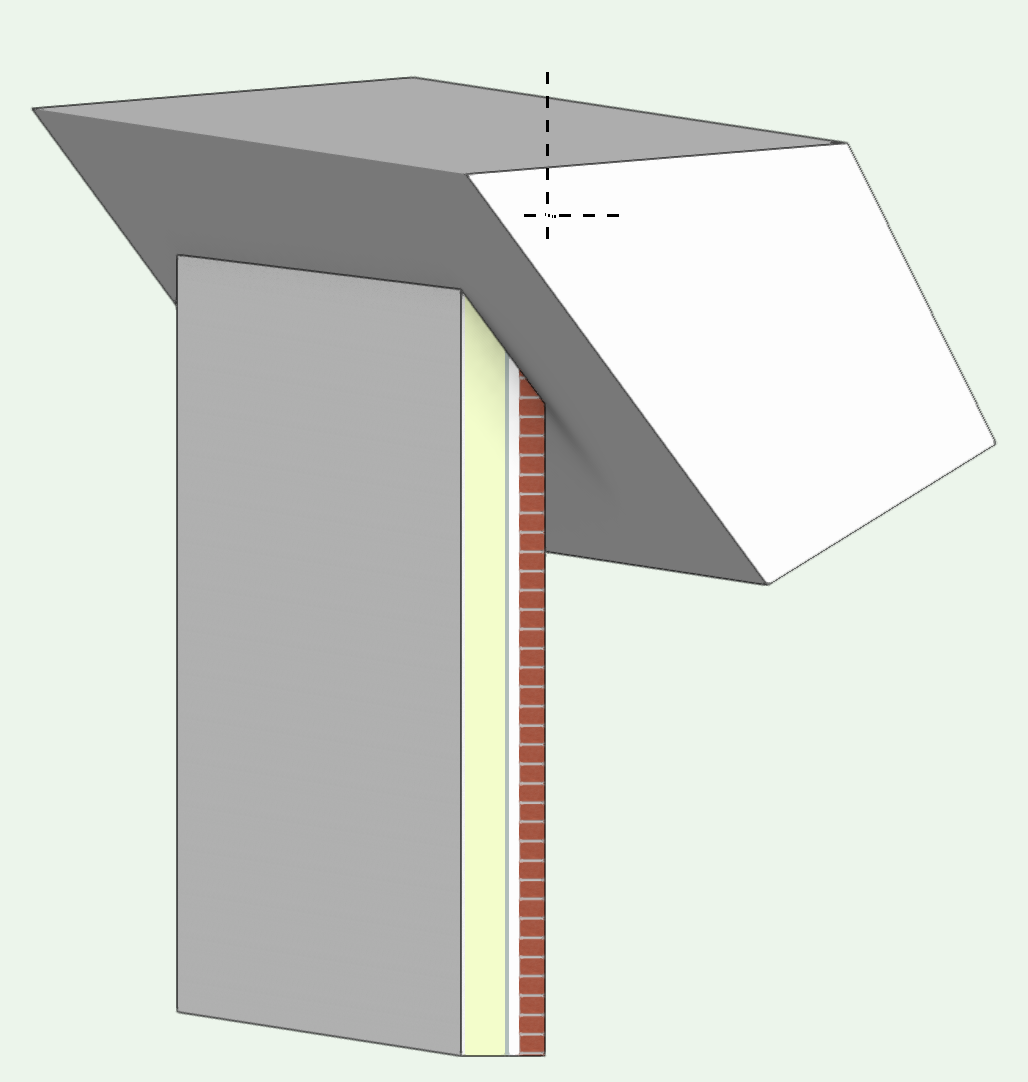
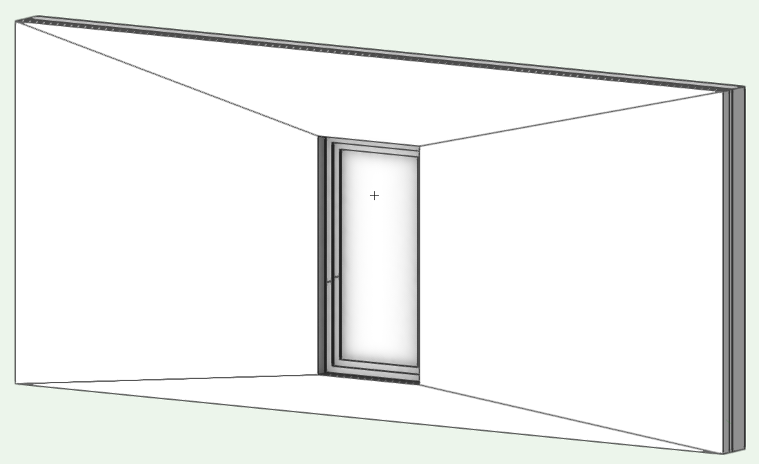
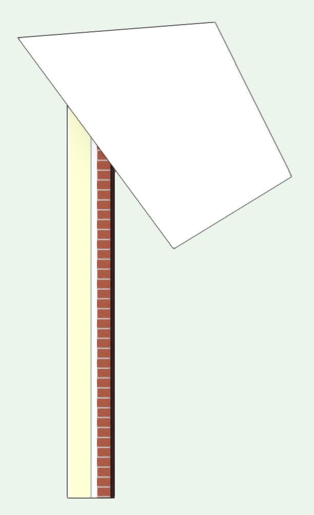
Hi RJR, try this.. Corners like to be mitred. Reduce the high wall to meet its neighbour and, when the walls join, the window will give up the fight and fall into line with your expectations. Then draw an additional wall above for the parapet. I've left this highlighted in the screen shots so you can see its a separate high level wall. Hope this helps you.


-
Can I Turn Off Renderworks For Certain Layers
Gadzooks replied to Jezza's question in Wishlist - Feature and Content Requests
Yes - good idea for speed. I'm sure that would be a much easier way when the model/scene allows. Probably just the thing for Jezza's second image. With the example houses from @JezzaI think this might need to be enclosing cube/cubes (certainly on the first image), which may be more work to construct and give varying degrees of success when rendered, as the cubes' various sides may be seen from some angles. (You bet it would be the most important one!). Plus you still have the original textures (washed-out) whereas I think Jezza wanted to have the scenic elements pass into the background a little - as if a white model. A bonus of the way I have described is that the street scene is unaltered and 'scenic' elements can still receive shadows correctly and therefore can be used to provide solar analysis - how the new build might impact the neighbours. -
Yes agree Zoomer - good advice. Its sometimes better to fine tune textures to achieve a required 'look' rather than be technically accurate.
-
Can I Turn Off Renderworks For Certain Layers
Gadzooks replied to Jezza's question in Wishlist - Feature and Content Requests
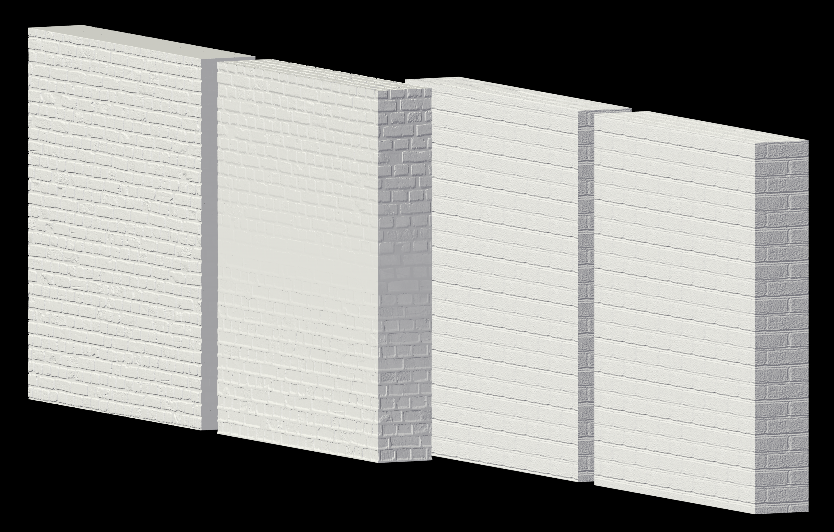
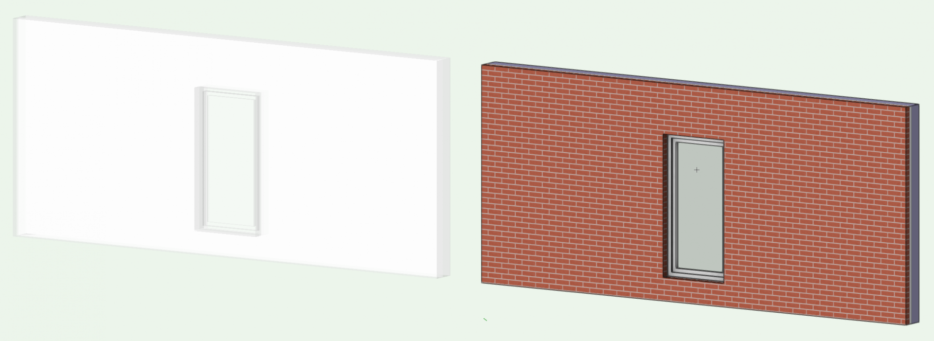
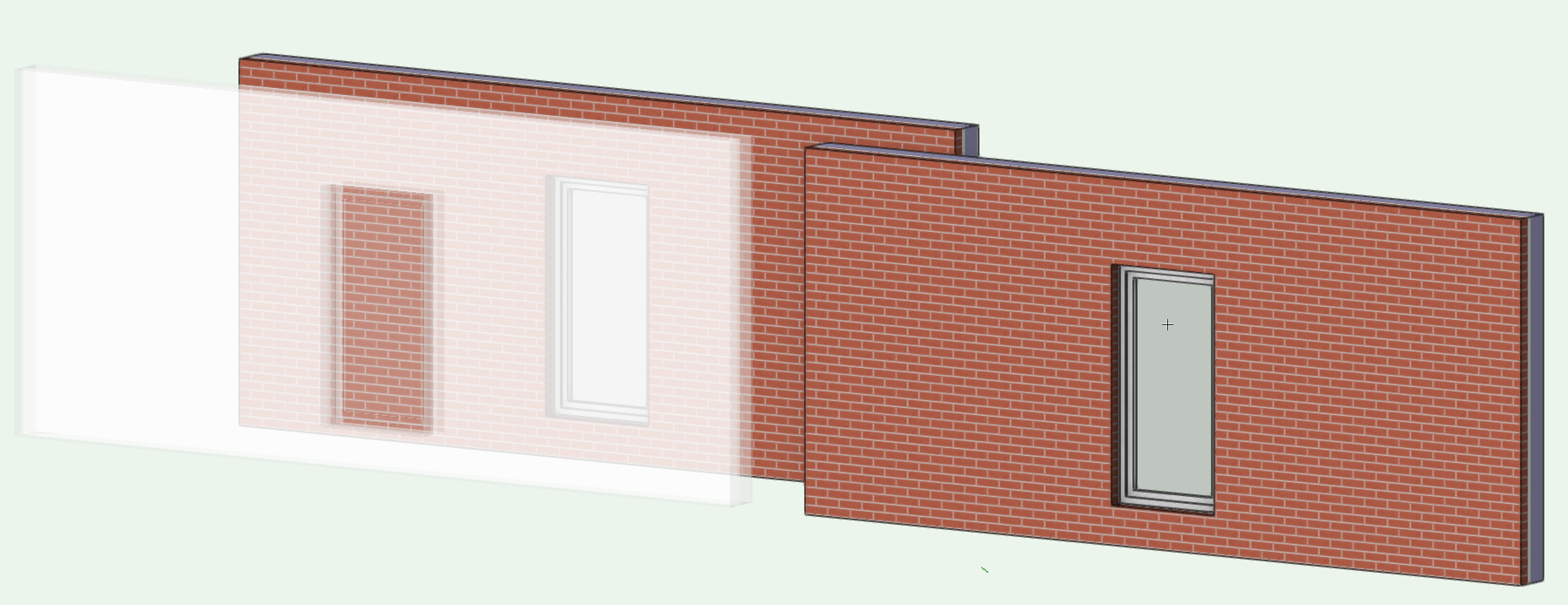
Jezza - group all the additional pieces you have created to provide the 'street scene'. Helps to keep the process tidy I think. Here I've chosen a piece of wall with a window to illustrate a degree of detail that I think you are wanting. Change all the 'scene builders' into 3D polygons with Modify>Convert>Convert to 3D Polys Some parts will split out, but I don't think this necessarily hinders the effect you want. This will have grouped all these elements and will have applied the fill and line colours presently chosen in the attributes pallet. If you set these defaults prior to conversion you may decide to choose (say) red fill for demolition. (Colours can obviously be chosen after as well) You can choose to render the scene now and the lines will smooth with Final Quality RW or better. However - to knock these elements back slightly - make your self a new texture (and include transparency) and apply to your elements. You may need to adjust the texture so that the balance of transparency shows the detail you require but leaves the street scene 'sketchy'. Here I've placed another wall behind to see through to and the 'sketch element' is at 20%. Bear in mind the model is now much bigger!! Depending on your scene you might want to knock back the level of detail earlier on in this process so the 'scenery' is appropriately sized. There's probably other ways to achieve similar effects, but I hope this helps. Out of interest - post the image if you use this process and like the result.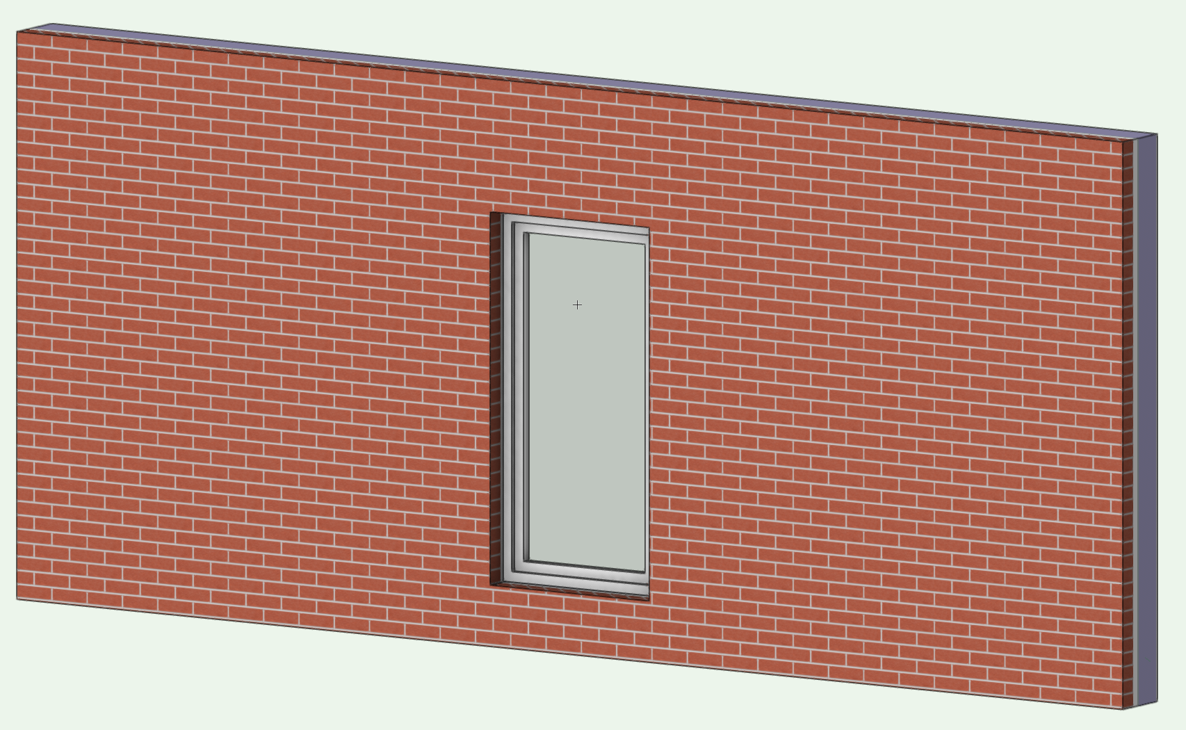
-
Library update - Summary
Gadzooks replied to AlanW's question in Wishlist - Feature and Content Requests
(not putting me off that easily ) Gotya Rob -- Surely still a goer though.. Would be good then if they were made available to download in two pieces of info. The user can choose:- First one (maybe for first download) of all info and split into pertinent sections. Fundamental, Architect etc.. Then a second one (listed by the date in the title) being just the updates info with both the 'add and subtract' details listed that would be reasonably easier to digest. Maybe?... -
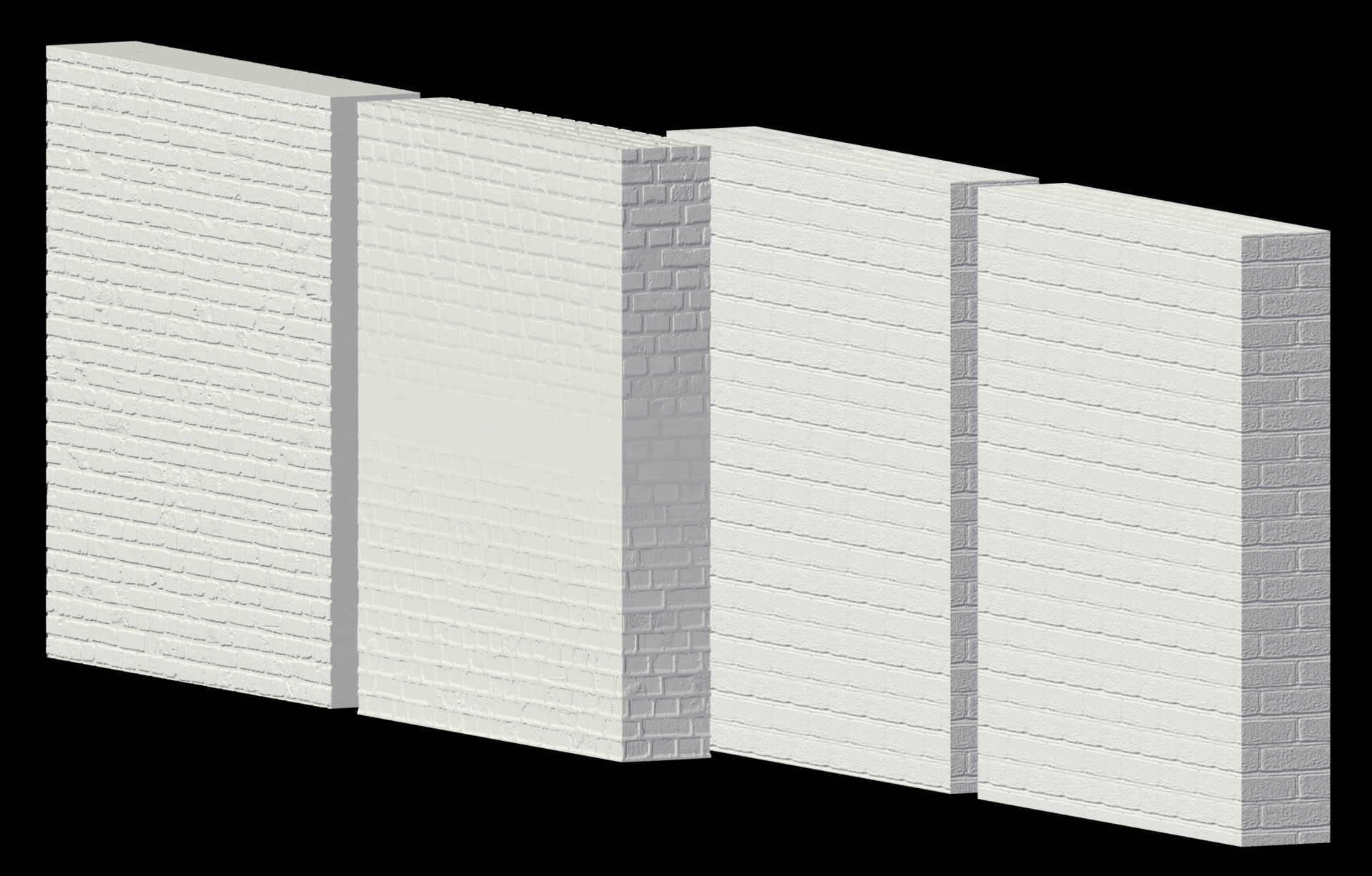
Hi markdd, Yes - weird. I've messed around with it for a bit and can't find any alternative to change the effect you get. (mapping etc..) However it does seem to be the texture, as your shapes (to the left and unchanged) work correctly with another brick texture I randomly chose and applied the same painted brick effect to (by dispense with the brick image and choose object attribute). As you can see, it doesn't seem the way the objects were created has any bearing on the alternative texture I applied so maybe the issue lies with the structure/makeup of the texture you've chosen? I'm out of ideas!!......
-
A quick fix could be gained from you uploading the file. Is this something you could do? Just trim it down to the objects you have shown, or copy that whole cluster (its not a group!!) to a new file.
-
Library update - Summary
Gadzooks replied to AlanW's question in Wishlist - Feature and Content Requests
Agree! +++++ This is a peculiar way to update a service provision and as you say, there are plenty of ways to deliver the notification automatically - maybe in the form of an excel file or at least something searchable. Just a thought....Assuming this is routinely delivering an 'over-write' rather than an 'addition', maybe it's what gets withdrawn from the data we would also like to know about. Obviously if that was the case, pre-notification please! -
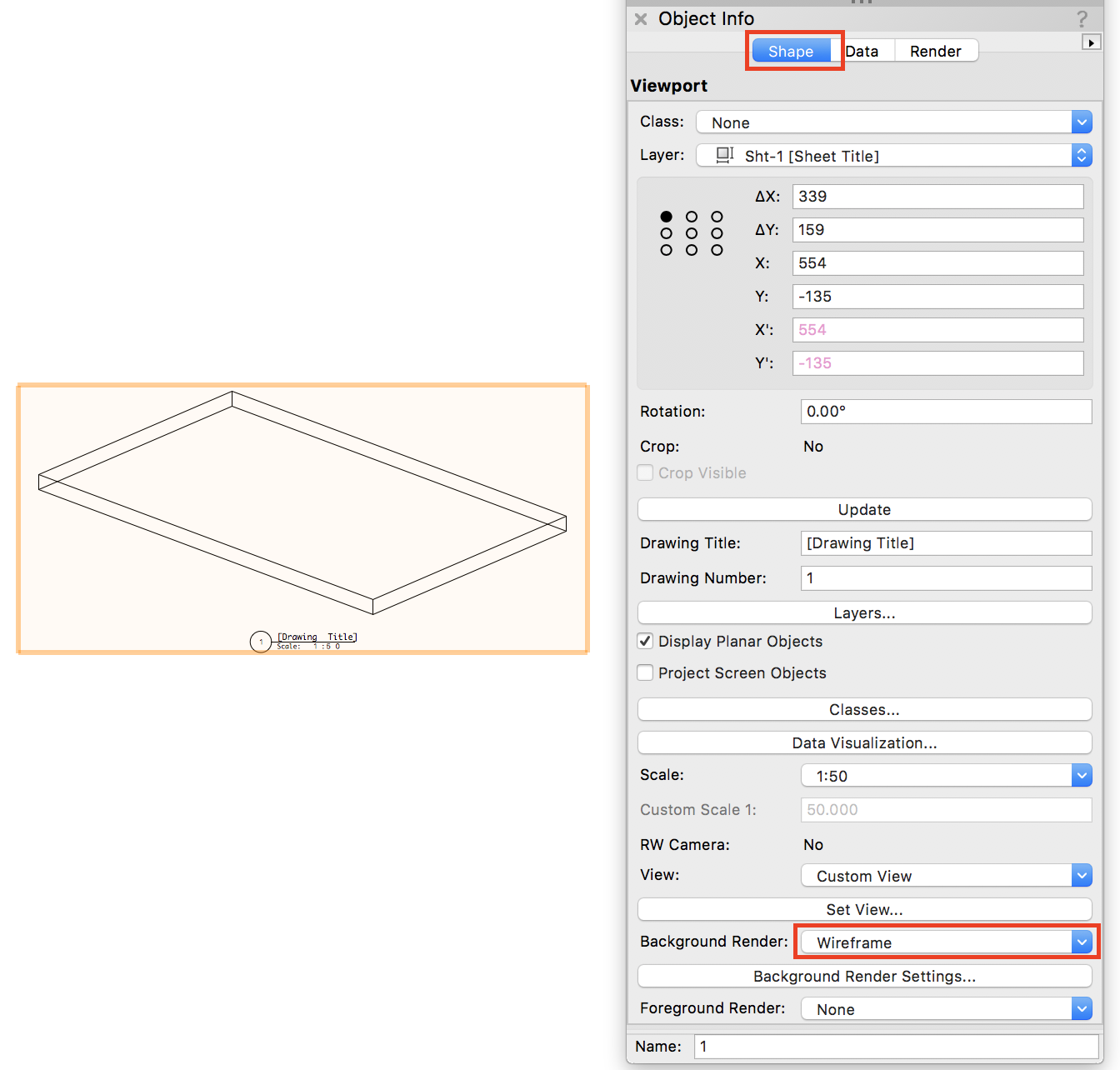
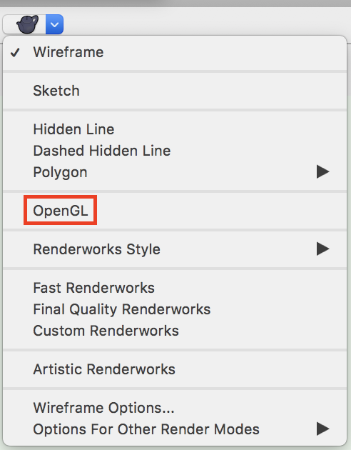
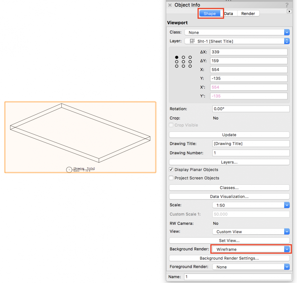
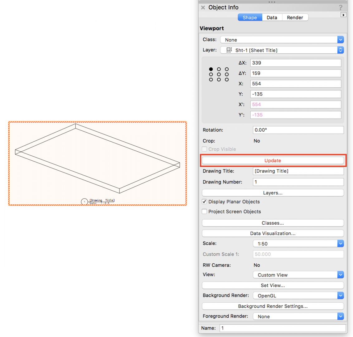
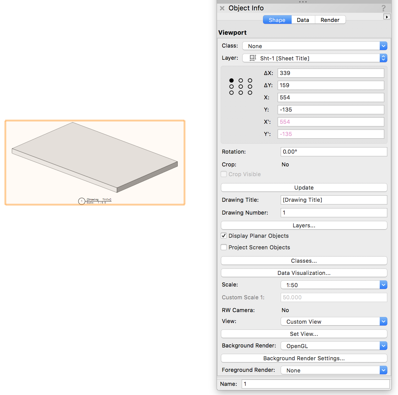
Hi Mattryan, Sounds like you need to chose a different way to view, as wireframe will always (as the name suggests) show only the structure (lattice) of the shape you have created - wether or not it has fill. What you've experienced is the difference between 2D and 3D. Try choosing OpenGL and try to work with that as your default. This will show solids as you wish them on layers. As you say you are in a VP, you will need to see the appropriate choice(s) in the OIP to achieve similar results. With your VP selected the shape details the options on the view you want. Looks like you have wireframe chosen as shown below. Choose Open GL instead.. Then choose to update as suggested.. Giving you.... Hope this helps.
-
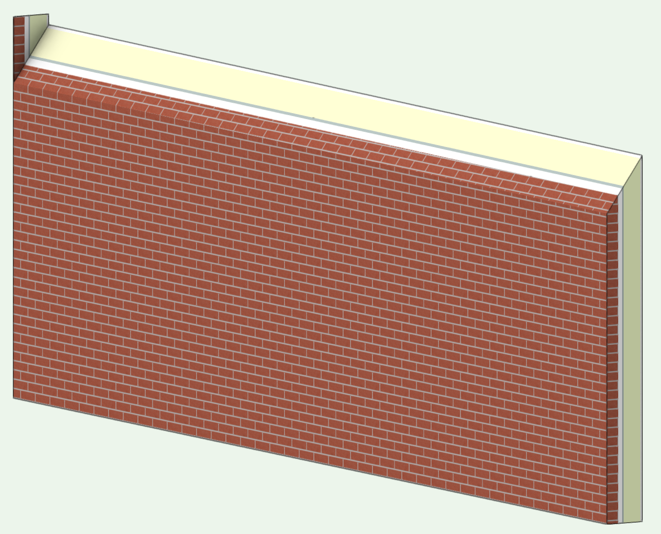
There is the wall recess command. As it stands, its not the 'sharpest tool in the box', but like a lot of VW options it can be used for a work-around. Choose your wall and create a suitably shaped 3D solid to overlap the top - the main thing (for you) will be to make sure the underside surface is at your required angle. Also make sure it's longer than (overhangs) the section of wall you want to modify (assuming you want to modify the whole of the wall length). You are now here.. Now create your 'recessed wall feature' by selecting both and choosing AEC>Create Wall Recess.... Its nearly there! But (isn't there always a 'but')... Unfortunately the VW boffins have created the outcome for an endcap so even though the solid is longer than the wall it goes to its default position. Depending on the direction you have drawn the wall it will be the endpoint. I'm not sure why thats required as any attached (continuation) wall would have its own endcap at that junction (maybe @JimWcould comment/investigate?), and try as I might I can't see a work around for it. Maybe others can take this solution and move-on further - all I know is as soon as you start to try and clip that toenail off the wall it returns to generic solids - exactly what you don't want. Certainly one thing you could do is start with wall height and underside of the 3d solid at the same position for a cleaner result. This would reduce the overall height of the 'toenail' - but obviously still leaves with a small portion of endcap You will have to disguise that! Until someone improves this tool. Hope this helps. --------------------------------------------------- @JimWCould the endcap be taken out of the result of using this process on walls? As stated above, I'm not sure of its requirement. If it were able to be dropped, it would provide a nice way of forming certain features in walls. Does it need 'wishing'? Or is someone going to say - this is how you should have done it...

-
Thanks for the file - now I see what you mean. I thought you were having problems with your 2/3D symbols, but you're using the MEP tools. I'm not sure I can offer you much help on this. These tools have been part of VW for ages. I take the MEP toolset to be for MEP guys (but if you are in 'pipes and wires' you'll no doubt be using one of any number of extremely competent MEP 2/3D CAD software packages). For MEP use (I'm in architecture) I can't get along with this tool set - and it would be (only slightly) better if the 3D element was editable. As its not, you (we) are stuck with 'show 3D detail' that is not at all detailed. To retain your info (assuming you are making use of the record data) I suggest you build your own symbols with as much 3D detail as you wish and embed the 'receptacle', 'comm device', etc...that has the record and 2D info you want to retain. Tbh, by the time you've started that process you'll be thinking about ditching the MEP object and refining your own bespoke set of symbols with attached records and any other touches that will be useful. I use my own 2/3D symbols and add to them as required. My aim is to show 'design intent' to both client and later to the services consultant(s) who will overlay their more technical design. It would be interesting to hear from others about their use of MEP objects.
-
Mmmmm...interesting. Could you post a simple file to show an example. Just a quick piece of wall with some outlets/switches.
-
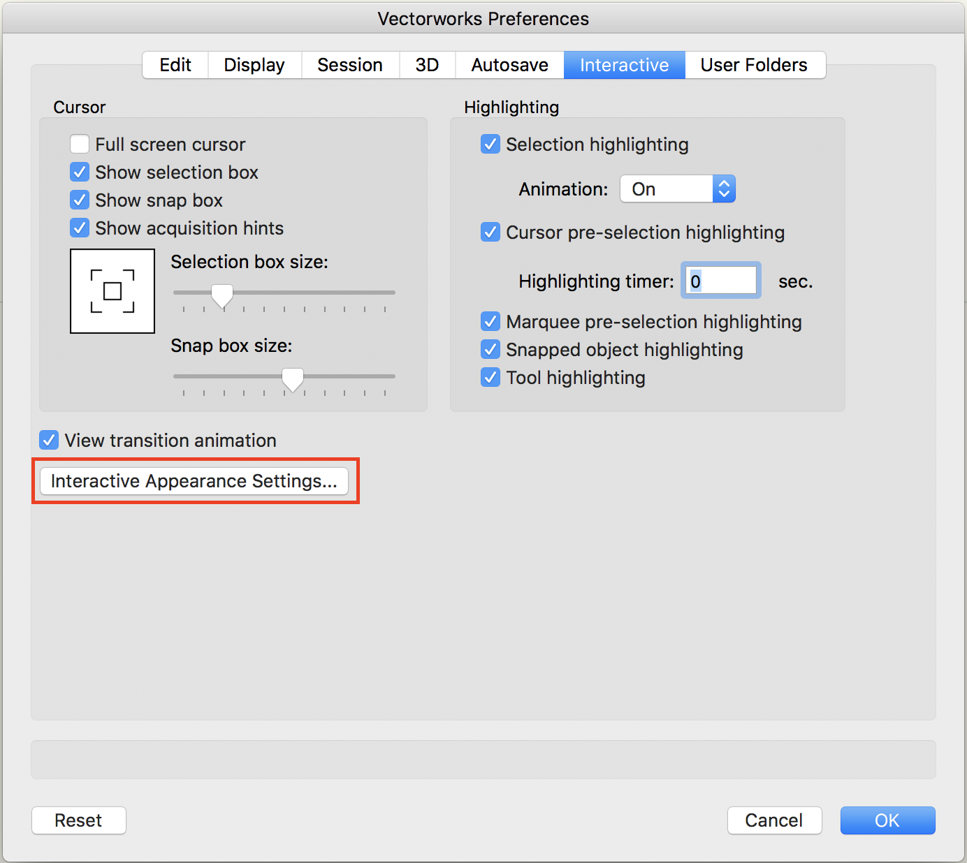
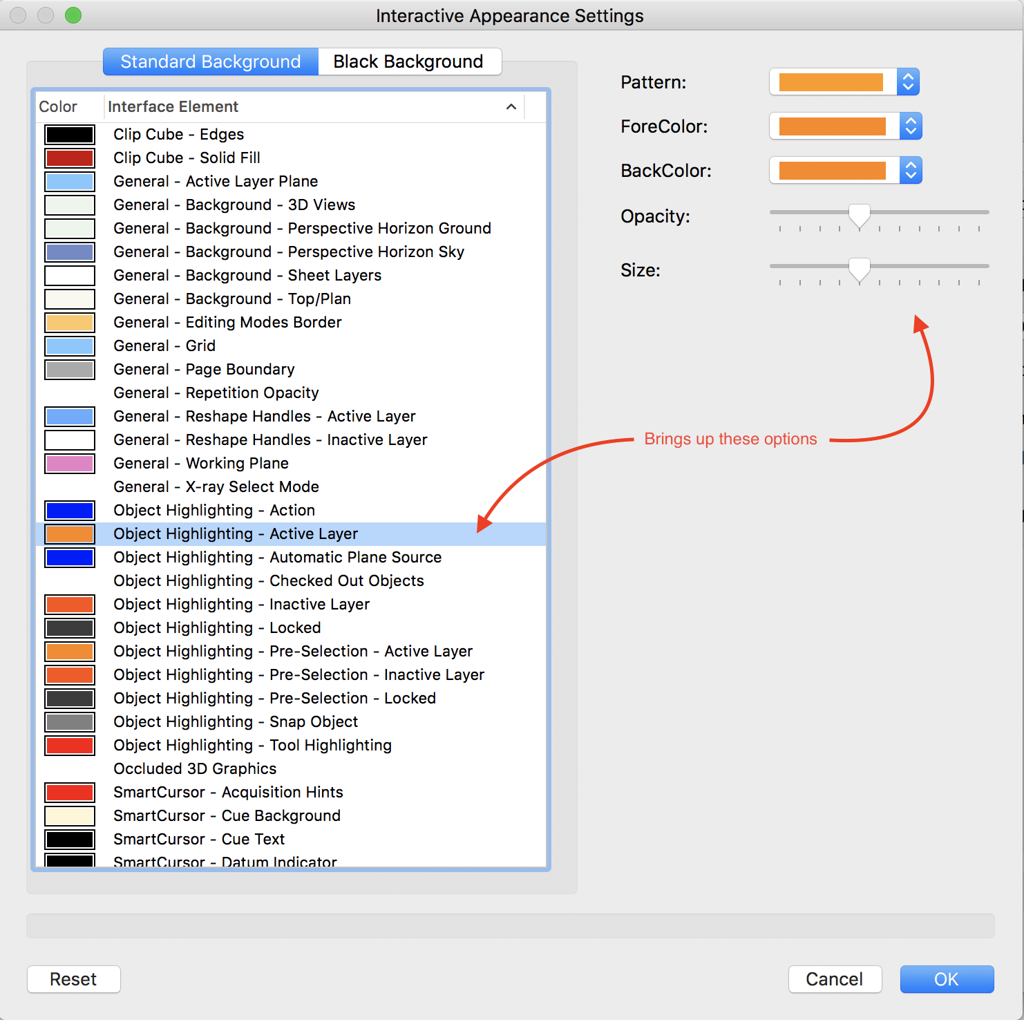
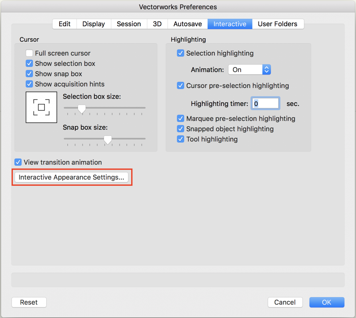
Just a thought - Have you changed any of the default colour settings that VW uses? If you look at Tools>Options>Vectorworks preferences and then choose the appearance settings... It offers colour choices for a wide range of actions/items.. You (or perhaps some other user) has changed the default opacity? ----------------------- Edit: Never having changed these options myself (why would you?), I've just tried this and not been able to recreate what you have. Sorry, this looked a solution.
-
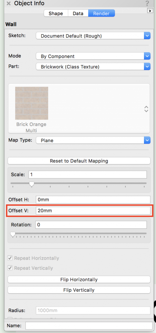
Hi Christiaan - I'm sure this is going to turn out that I've not really understood your problem correctly, but you can adjust the texture mapping by the 20mm just by highlighting the wall and entering the adjustment on the OIP.
-
Feel the love. Its great when you see how this forum works and this thread shows it from start to finish.
-
Exactly - I'm unsure as well. I think (VW Inc are you listening?) the least I hope to get from the conference is who's in the seat now. I'm getting emails from both VW UK and from Exertis about 'their' conference. I've asked before (no response from VW Inc) , but could the new UK hierarchy be explained please.
-
VW 2018 Installation License / EDU->PRO
Gadzooks replied to Charlie Winter's topic in General Discussion
Just a stab in the dark - Something to do with whether you downloaded the correct software your serial number begins with? It'll be either E or the B,C or G option, and using the incorrect one will cause mixed problems. -
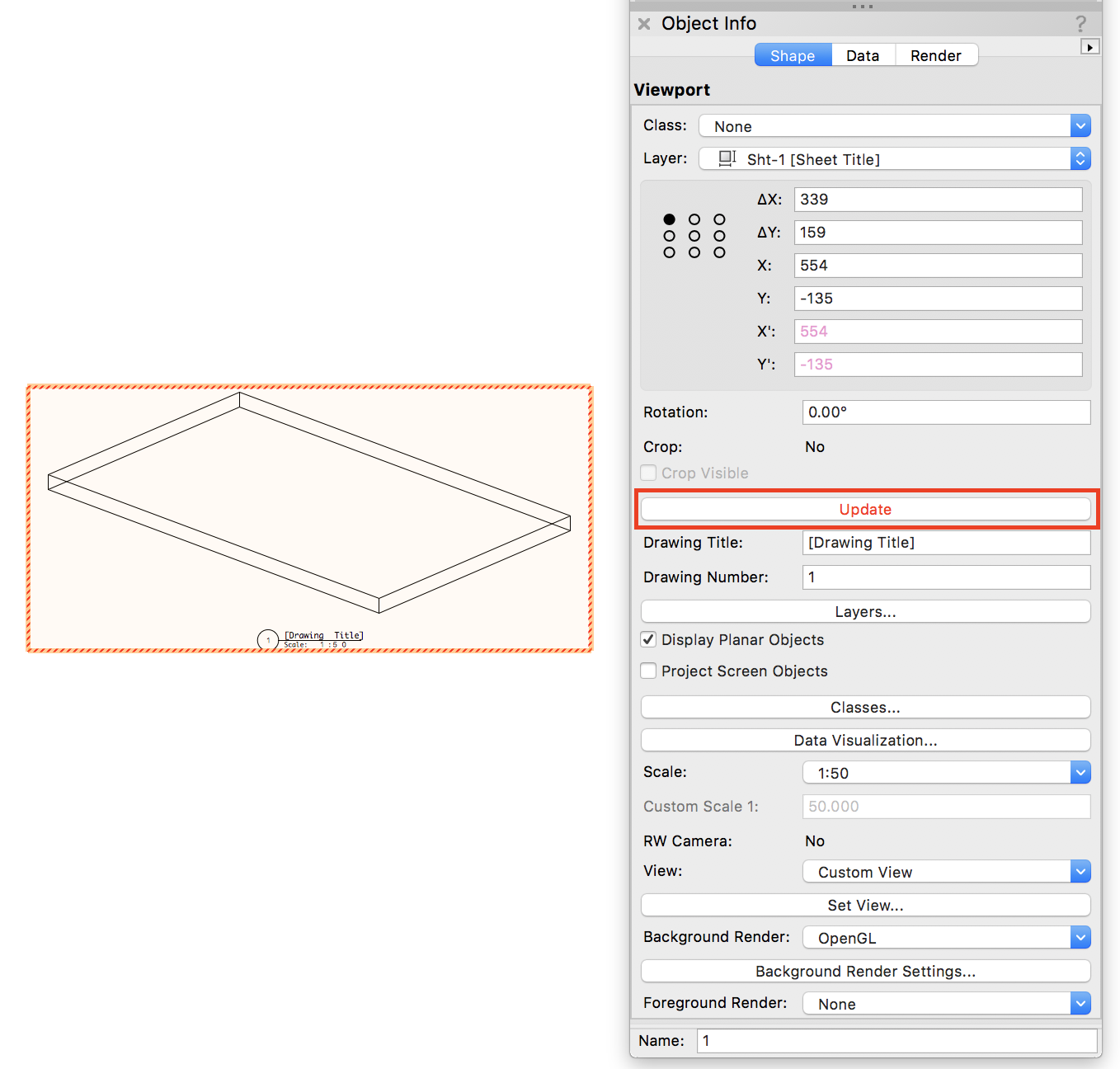
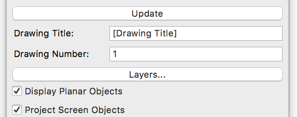
Yes there is. The information is shown in the OIP. Click on the VP to bring up the OIP.... It defaults to [drawing title] to suggest you might want to provide a better description, but to take all text out of this text box works equally well and will leave you with just the drawing number. and scale. This is also useful at VP creation as you have the same set of options offered. Assume this is what you wanted?
-
I have VSS (I know - there must be a cream for that). I've downloaded 2018 but, as I'm in that 'can I trust this on live projects' place, I continue to use 2017 atm. Whilst I'm using 2017, VSS is notifying me that 2018 is available. Very helpful, but now getting a little annoying. Yes - even though its just a click to dismiss, it disrupts concentration. My thanks to the helpful team at VSS, I realise its just a pleasantry, but can I suggest/ask.. Can the notification use a 'don't tell me again' checkbox? Why can't VSS check the records and see whether a certain user has already downloaded. And yes, I've thought the next bit through (just because you've downloaded you may not have got it up and running correctly). I have used it and I continue to 'test' my design workflow with it. So... Why can't VSS make a check from the VW 2018 activation records? As I said - Just a comment.
-
Where did my, back and rear views go?
Gadzooks replied to Kaare Baekgaard's topic in General Discussion
Haha - Just getting there myself -
Where did my, back and rear views go?
Gadzooks replied to Kaare Baekgaard's topic in General Discussion
Ok - (should have looked a little closer) Just seen you have multipane available in the dropdown - so you are on 2018 -
Where did my, back and rear views go?
Gadzooks replied to Kaare Baekgaard's topic in General Discussion
This sudden? Could you confirm which VW you are using please. (Would be helpful if you used a signature with this information in)