


Marissa Farrell
-
Posts
1,474 -
Joined
-
Last visited


Recent Profile Visitors
23,891 profile views


-
Get Object Variable has a different use-case. In this instance, you want to use the Get Record Field node. Here's a small network that should solve your problem. MassingModelMarionette.vwx
-

Vectorworks 2023 PC python numpy compatibility
Marissa Farrell replied to John Cox's topic in Python Scripting
Great, thanks for the update! -
Vectorworks 2023 PC python numpy compatibility
Marissa Farrell replied to John Cox's topic in Python Scripting
@John Cox Can you tell me more about why you were uninstalling/reinstalling Python versions? Also, which platform are you working with? -
Handle a wall from a selected plug-in object
Marissa Farrell replied to Andreas's topic in Python Scripting
Conveniently, for objects in walls you can just use vs.GetParent() -
This shouldn't matter, my first test was with a black symbol that I later converted to red. I'll make a note to look into this in a bit.
-
You can remove Marionette menu commands by navigating to Marionette Command Library.vwx (Go to [Your User Folder]/Libraries/Defaults/Marionette) and delete the resources in the RM that correspond to the menu commands you'd like to delete. Then you'll likely need to restart VW to show the changes.
-
Hi! You can use the Objects by Criteria node and set the Criteria to ((SEL=TRUE)) (You can also use the dialog that is presented using the "Criteria Configuration..." button in the OIP) Replace your Name node with the Obj by Crit node. Sometimes this is finicky, though, so please if you run into an issue send me a DM with the file so I can take a look and forward it to the engineers if it's something we may need to fix/account for 🙂
-
draw an polygon spaced across a 2D path object
Marissa Farrell replied to Jayme McColgan's topic in Python Scripting
The easiest way I've done with with Marionette was to convert a copy of the poly to a NURBS curve and divide the curve into segments to get the points along it. I'm attaching a file to demonstrate. If you just want the 2D points instead of the 3D points, you'll need to remove the Z value from the resulting list. Div Curve.vwx -
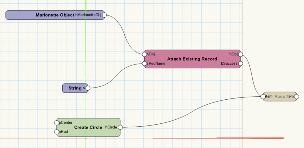
Hi Stefan! I'm attaching a simple file that I hope may help, but I also may be misunderstanding your question since you haven't provided a file to work from. Please let me know if this helps, or if I need to go in a different direction. In this file, there is a circle Marionette Object that attaches the record within the network to the circle using the Marionette Object node (which returns the handle to the Marionette object) Creating a symbol of this Marionette Object creates a Marionette Object Style (which can be found in the folder of the same name within the Resource Manager. The resource shows the attached record in the RM window. MarionetteCircleSymWithRecord.vwx
-
Is this a Vectorworks worksheet, or is it an external excel worksheet?
-
Right now there isn't a node for that. What exactly are you hoping to do? Take the top face and get the 2D representation? The bottom?
-
Thanks, @Jack_Moleta I'll put a ticket in for this 🙂
-
Marionette "Ordered List" : how to add some more items?
Marissa Farrell replied to Minethun's topic in Marionette
Hi! You have options. If you remove the line of code at the top that begins with #COMMAND then you can edit the python script Otherwise, you can wire two Ordered List nodes together, use the output from the first one as item1 in the second. -
@Sibbi123 I'm not sure this works even doing it manually. I tried ungrouping your geometry results and performing the Clip Surface command (which is what the planar boolean in subtract mode does) and it doesn't do anything either. Can you show me where you got this tutorial from?
-
vs.SetAngle(h, value) - running issues
Marissa Farrell replied to Andreas's topic in Python Scripting
Thanks! I just had the chance to check this myself and wasn't running into issues, so this helps me to not need to ask for more information 🙂

