
SBarrettWalker
-
Posts
335 -
Joined
-
Last visited


Recent Profile Visitors
7,997 profile views


-
In Vectorworks 2024, there are now viewport styles, and with viewport styles you can set the drawing label to be "by style" meaning a particular drawing label style can be added automatically to any viewport of that style.
-
 This file should now be available to use in 2024!
 -
You would need to create a custom node using the formula vs.GetPluginStyle(hObject). I created one in Vectorworks 2023. Get Style Node.vwx
-
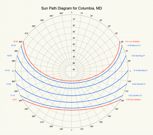
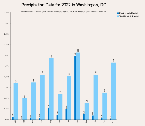 That is very odd. I tried Paris as well, you are right, no data shows up in the graph, but data does exist and is downloaded, so it SHOULD show up in the graph. I will have to research why.
 -
@GatRed have you tried other locations near where you are trying? That error pops up when there is no data coming through. Does the error show up every time you try to edit the chart or only the first time?
-
Version 1.0.0
85 downloads
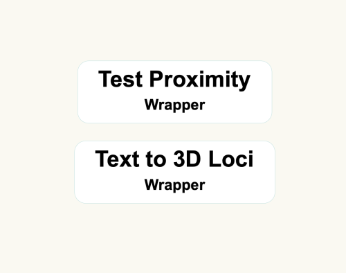
These scripts are similar to networks I posted in January of 2019. Here is the link to the previous post. The Test Proximity script is the same one as in the older post, but has been updated to Vectorworks 2023. These scripts are primarily for Landmark users - they can be used to convert a file that contains 2D geometry with unassociated text labels to 3D loci (if the text is a number value representing an elevation). To use these wrappers, first group the geometry and text labels you want to convert and give the group a name in the Name field of the OIP. Then copy/paste the wrappers into the file and set the parameter "Group Name" in the two wrappers to the name you gave your group. Next, run the Test Proximity wrapper. Lines between text and geometry will appear. If there is a line between each geometry and label pair, you can run the next wrapper. If there are multiple lines from a single piece of geometry to more than one text label, adjust the text labels in your group, placing these particular labels closer to their respective geometries and rerun the Test Proximity wrapper until there is a single line for each text and geometry pair. Finally, run the Text to 3D Loci wrapper to create 3D loci at the same location as the 2D geometry with a z-height that matches the text value. -

Version 1.0.0
136 downloads
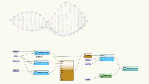
Here are the files used in the webinar, Algorithms-Aided Design in BIM Software. "Sample Script" is the file that was used for the full demo, and "Panelization" and "The Greyhound 2" were used as examples. -
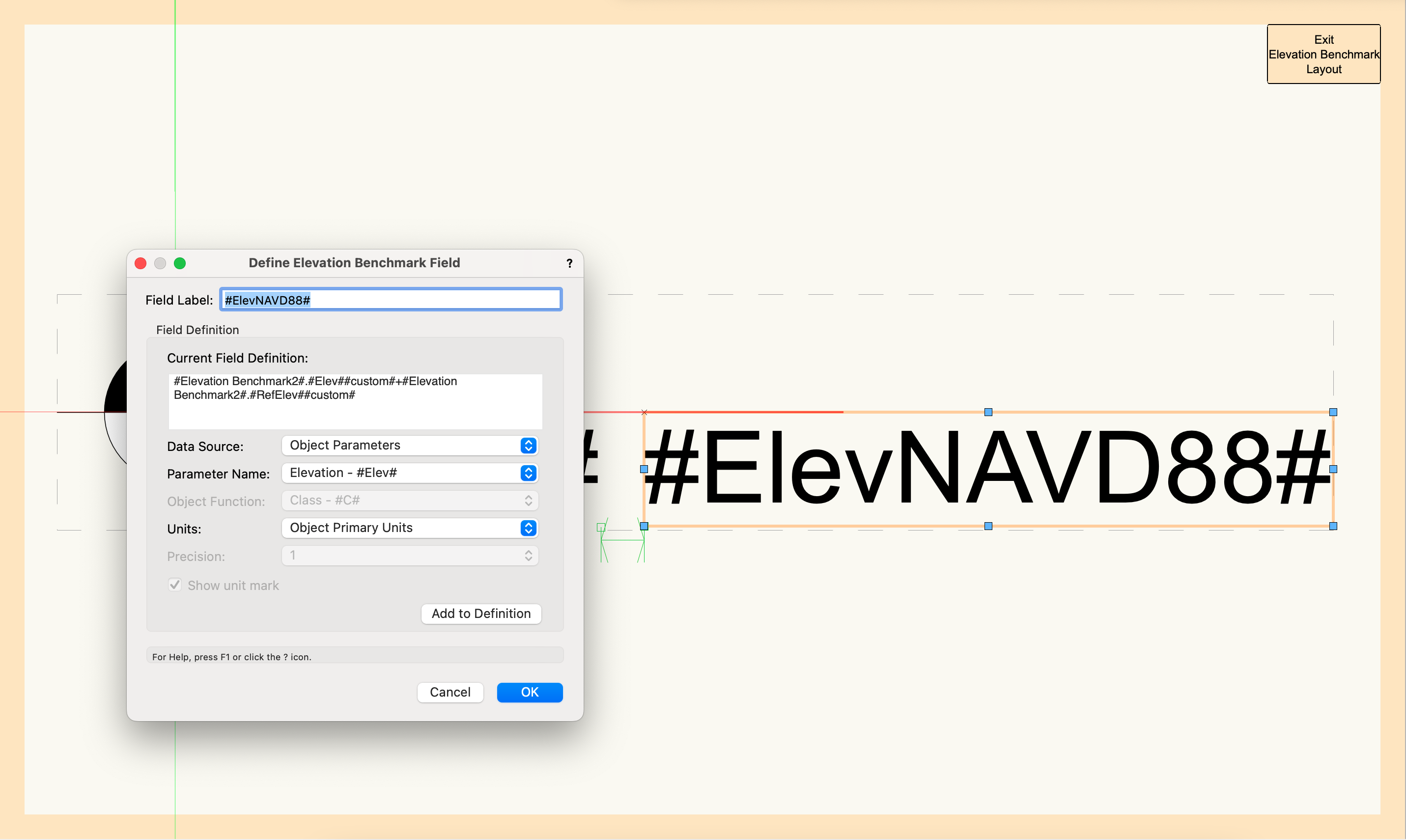
2023 Benchmark Tool - How to display relative Elevations + NAVD88 Elevation?
SBarrettWalker replied to maxstk's question in Troubleshooting
As for the styles that are in the feature video, they were customized from the the existing styles in the default library. I think the library technically has all the different possible "dynamic texts" that you might want, but there is probably not a style that would match exactly what you need. It is a hard balance not to overload the default library with tons of styles but to make sure enough are there to help someone find something customizable. I am attaching a file with all of the elevation benchmarks used in the new feature video that weren't from the default library. Elevation Benchmark Resources.vwx -
2023 Benchmark Tool - How to display relative Elevations + NAVD88 Elevation?
SBarrettWalker replied to maxstk's question in Troubleshooting
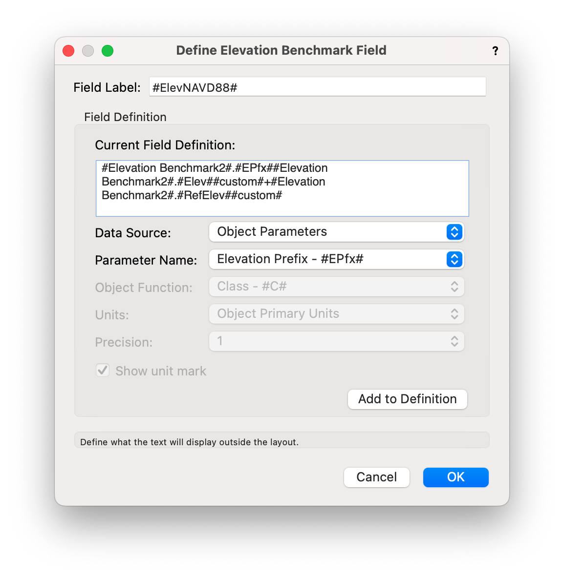
Hi Max, you were on the right track, but you need a different formula to read the project elevation + the reference elevation. I believe the new feature video shows a different field value, the one for project elevation. The reason the formula looks so complicated in the video is it has a fancy IF/THEN statement to show a "+" in front of the value when it is positive. Attached is a screenshot of what the formula should look like and a short video on how I built that formula. I removed the IF/THEN statement to make it a little simpler, but if you really want to have the plus sign in front of the value, I recommend you set it in the "Prefix" field of the Elevation Benchmark settings as that is simpler to report. I have also attached a screenshot of what the formula would look like to report the prefix along with elevation + reference elevation. This new tool is very powerful, but it can be complex. There are default styles that try to cover most scenarios, but if you have suggestions on what to include in the default libraries to make the styles easier to use or to understand that would be welcome! I hope that helps, Sarah Screen Recording 2022-09-27 at 1.20.47 PM.mov

-
@MaxStudio Make sure that there aren't any other characters in the name like "-" or "/", only numbers and letters. I can't remember if spaces could be used in 2016 or if it had to be underscores.
-
I also would like to mention that there is a Batch Rename command in the Tools menu that allows you to find and replace, add prefixes, suffixes, etc. This was not available when the Rename Classes Marionette menu command was posted to the forum. Because you would have to run it and set it every time you opened a new file, the menu command wouldn't really be any better than using the Batch Rename command.
-
@E|FA in order to reset the default mappings, go to the settings dropdown in the top left corner of the Data Manager and choose Vectorworks Defaults. This will reset all of the mappings that you have done. Unfortunately, there isn't an easy way to partially undo your mappings. If this works then great, but if you are still having issues, you can send me the file and I will look it over.
-
Hello @E|FA, I was able to get #WS_OBJRVALUE# to read the correct R-Value of an object, even if it is overridden manually. I have a attached a file that has a working data tag. This file also has R Values and U Values mapped to a custom record. Doors, Windows, and Walls all have their R- and U-Values mapped in the Data Manager, so even though it is in a custom record, the value is coming from the object and the record is automatically attached to the correct objects. The Greyhound.vwx
-
You should know that there is a data tag (new in 2022) that will read the height of any point you click on. It is in the Spot Elevation folder of the tag in the default library, and if you have your layer plane set to automatic and click on the horizontal face of an object, it will read the real height of that face. If you click on a vertical face, it will read the height of the point at which you clicked. I would give this a try first to see if it will work for you instead of building something custom in Marionette.
-
Component Wall from Surface
SBarrettWalker commented on SBarrettWalker's file in Marionette - Networks
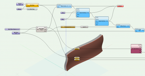 @Samuel Derenboim There isn't a version of this script that already exists for Slab and Roof PIOs, but it would definitely be feasible to create. It is important to note that it doesn't actually create a wall, it creates 3D solids that mimic an existing Wall Style's components, so this could be reworked to read a slab style or a roof style. However, you could just as easily build a Wall Style with the correct component thicknesses and use it on a horizontal surface and you will get the same result.