
zoomer
-
Posts
8,888 -
Joined
-
Last visited
Content Type
Profiles
Forums
Events
Articles
Marionette
Store
Everything posted by zoomer
-
I think that was the first thing I added when creating a custom template. Nevertheless I wonder so often how many not-from-my-template-Files I have to open and really need to again import my Render Style(s) from one of my own files ...... So it would not be that bad to have an option to edit VW's delivered default Render Styles (?) on App level ....
-
Window with symbol: inconsistent behaviour in Horizontal Section Viewport
zoomer replied to line-weight's question in Troubleshooting
But if I got it correct, (for me this is new) for custom Windows, not possible to create with VW Windows, adding custom Window geometries as Symbols inside the Window PIO is still a valid, if not recommended, Workflow ? My experience with such combinations from Revit Door imports so far was just .... - Door PIO Dimensions neither read/care of/take over actual Revit Door's nor their (simlified) Boundaries dimensions - All such Doors in VW just showed the same default VW Door dimensions - changing dimensions in Door PIO has no influence to Symbol Door geometry/is ignored (opposed to e.g. a custom Symbol for a Door Leaf - which would be simply scaled in such circumstances) - renaming the Symbols used in Doors in RM, leaded to breaking Links/loss of the geometry of these Doors (how to ever remember the overwritten (illegible) former Revit name or how to know which Symbol to reassign now ?) -
Sounds cool .... I meant, select 2 or more Solids : Menu > Model > Add Solids (Boolean Operation) "If applicable" .... that would be the easiest solution. I think keeping safety area volumes inside Fixture Symbols makes much sense. But I currently have no idea of how to workaround your transparency problem. Overall I think stacked transparency is the smaller problem ..... You can still examine the 3D model in shaded mode, look at it from all directions and easily see where potential objects might enter/collide with the safety area where they get partly occluded by the transparent Volume .... You may see it even better when 3-5 transparency layers overlap .... My only other ideas are, maybe even make volumes fill solid if you don't like the transparency effects and for temporary collision examination activate the safety area Classed or make them invisible again for designing or other purposes. Or control visibility by Data Visualization
-
Window with symbol: inconsistent behaviour in Horizontal Section Viewport
zoomer replied to line-weight's question in Troubleshooting
Don't need that often so not experienced. But I just assumed you could basically do the same with Symbols ... E.g. by Data Manager. I mean it was always proposed, if you can't get your desired Window by VW's Window Tool - use your own geometry in a Symbol and insert it into a Wall .... And I also heard that people insert Window PIOs in Symbols (to only make as much custom geometry manually as needed but still make use of Window's parametric comfort) But never before heard using Symbols in PIOs intentionally. I just know that feature exists from my Revit imports. Where my experience with that soon made me think that is pretty useless .... (For several reasons .....) -
Window with symbol: inconsistent behaviour in Horizontal Section Viewport
zoomer replied to line-weight's question in Troubleshooting
Got it. I am not sure how this really works. I thought in the past, when Walls were more 2D-like organized, inserting a Symbol without a dedicated Cut Volume into a Wall, would cut automatically through the whole Wall depth and just use the overall Symbol boundary rectangle/cube as a "cutting" Profile (?) Then this should work for your standard rectangular geometry without manual cutting geometry part. (Or was it by adding Points to the Symbol standard geometry ?) And I am not sure how well Wall Closures accept/recognize inserted Symbols or extra Cut Volumes in general. My first thought would have been to play with the Window Settings, to make Wall closures using the "virtual" Window data. But not sure if Windows will treated completely different as soon as they are based on an "overall" custom Symbol. But maybe worth a try. -
Create a surface bettwen two elipses (X,Y)
zoomer replied to Cristiano Alves's topic in Solids Modeling
I think it is not a Tool but a Command. "Compose" from the menu. Also thought about Revolve. But did not answer as I was not sure if it would work a) that way in general and b) with ellipses I thought about starting with circles and arcs or just by a globe and using 3D Manipulation Tools. Which in effect would just do a nonuniform scaling .... which may look pretty similar - but not the same as elliptical. And so far i assumed true Ellipses are mandatory. -
I don't think so. I think this is proper behavior of partly transparent objects occluding each other. Usually that is the way you want to achieve to make the geometry legible. And I can't remember to ever have seen such transparency effect you ask for, in any other CAD or 3D Software I used. I think you want these Volumes inside/being part of your Fixtures Symbols. Just like Plant Symbols can have such a safety area Volume for roots area of trees. Or I have seen similar for some building parts. So you do not really have access to the Volumes geometry. But so far I have not seen that such safety area dummies do overlap. In BIM these are used for collision detection. But if these overlap themselves it would not help the collision detection calculation either. The effect you want to achieve would mean or lead to combining these overlapping safety area Volumes by a Solid Addition. Which perfectly describe the whole tabu area .... That would also solve the Transparency effect and collision detection calculation or visual control legibility. But of course, separating safety area Volumes from Fixture Symbols would make future changes of Fixtures more tedious and probably more error prone.
-
^ would be interested too ....
-
Window with symbol: inconsistent behaviour in Horizontal Section Viewport
zoomer replied to line-weight's question in Troubleshooting
I do not really understand the reason why you insert your Symbol custom Windows into the Window PIO Container. Wouldn't horizontal Section (and probably Wall Closures) work better with Symbols directly inserted in Walls ? In this case you don't want 2D appearances replacing the true cut appearance. I think in a Wall cutting Symbol you could do so if you want. But I would think this would no more work if such a Symbol is "occluded" for 2D appearances when inside a PIO (?) -
I think C4D has not had the most flexible or capable customization interface I have seen .... E.g. Modo was far more capable. A Window Viewport could be anything, a Tool Palette, a Drawing Window, Render Preview, .... one developer even integrated a Tetris game into a Viewport. But how easy it was to screw up the whole GUI permanently. But by far the most easiest to use, understandable, predictable and reliable UI editing I have seen so far. Which is worth a lot !
-
I thought about just numbers are easier in conversation. But I am not sure if marketing department will abdicate the positive impact of "Update". I was pretty OK with "Service Pack" in the past though. Pre VW 2024, VW had bugs and I was mainly happy to see them fixed by Service Packs. (If VW 2024 still would have bugs, I maybe would still even prioritize bug fixing over new features "updates" ...) And I always associated "Service Pack" with so positive feelings, like VW support caring of me or even getting a whole "Pack" of Service and such. "Update" feels a bit cold and impersonal.
-
Exporting Sheet Layers to new VWX file
zoomer replied to AndySmithArch's topic in General Discussion
I think this is the problem .... If they need to edit the Viewports (!?) copy the Sheet Layers and name it in a way they will find it, send them the File copy (!?) If they need the SLVPs just to see what they edit/add/replace in the File (!?!?) offer them Project Sharing ? If Vectorworks would offer a Speckle Connector/Support, you could collaborate and each one would work in his own Branch of the Project and you could switch or merge branches like in Software Development. I am a bit confused. I would therefore recommend @Pat Stanford proposal ..... -
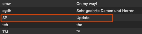
So if I ever can update my old brain from embossed "SP" to "Update" I need a proper official abbreviation for forum conversation. VW UPD2 ? VW U2 ? EDIT : Solution > Settings / Keyboard / Replace Text
-
I thought I had that yesterday too sporadicly. But I tried again today .... (Got a new Sonoma 14.2 Pubic Beta Update last night ...) Well, beside that I need to keep holding the B key .... It also seems to work fine here. Even when no Tool active. I can shake my cursor as much as I want .... my X-Ray bubble follows my cursor reliably.
-
VW2024 Doors - how to change hinge side on a swing bi-part configuration?
zoomer replied to StefanoT's question in Troubleshooting
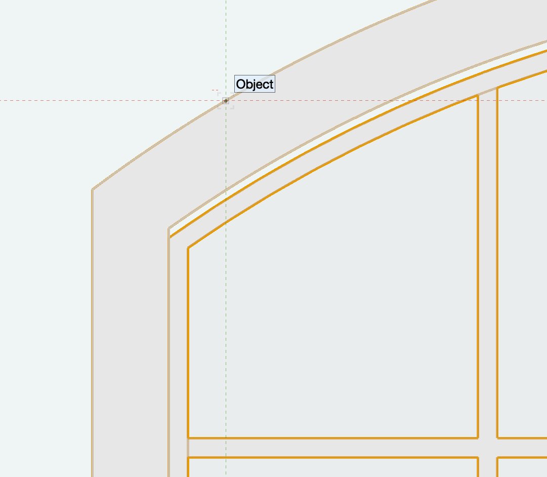
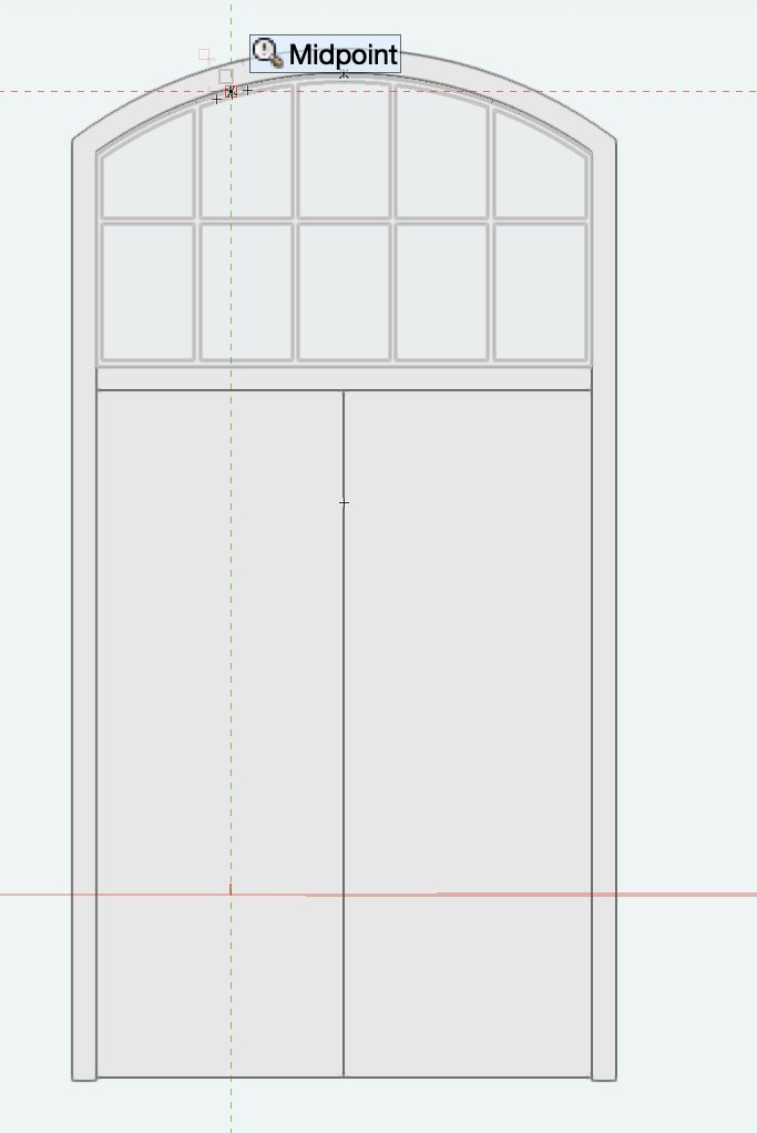
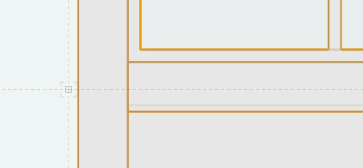
Sorry @Matt Panzer 🙂 Back on topic - with a Door. Just sketched that VW US Door from a photo for someone on the german Forum. As this configuration is said to no more working in 2024 CW Doors ..... (?) For fun I tried the new 2024 feature, to get a gap under the Leafs and set 1 cm. While creating, Preview in Door Settings looked first like adding the gap to the upper side !? But the gap below worked correctly in geometry. But now, when I look at that Door from Front View ..... It looks like the gap below the Leaf ..... (Why only below the Leaf ? I would like to set small gaps around the whole Leaf(s), when using same materials to make Jamb/Leaf visible in Renderings) .... is done by just moving Leafs in Z (?) When the Door selected it looks like the Leaf(s) overlap the Jamb. (I my case not Jamb but Mullion - because of the Transom) You can see the semi occluded Leaf Top Edge above the bottom Line of my Mullion (and under my dashed cross hair cursor) But what I really wanted to say that I think it may not be "WAD" .... In Front View, on Top of my Transom .... it looks like VW added a copy of my "under the Leaf gap" between Top of Transom and Top of Jamb !? And finally my Door File : Untitled 5.vwx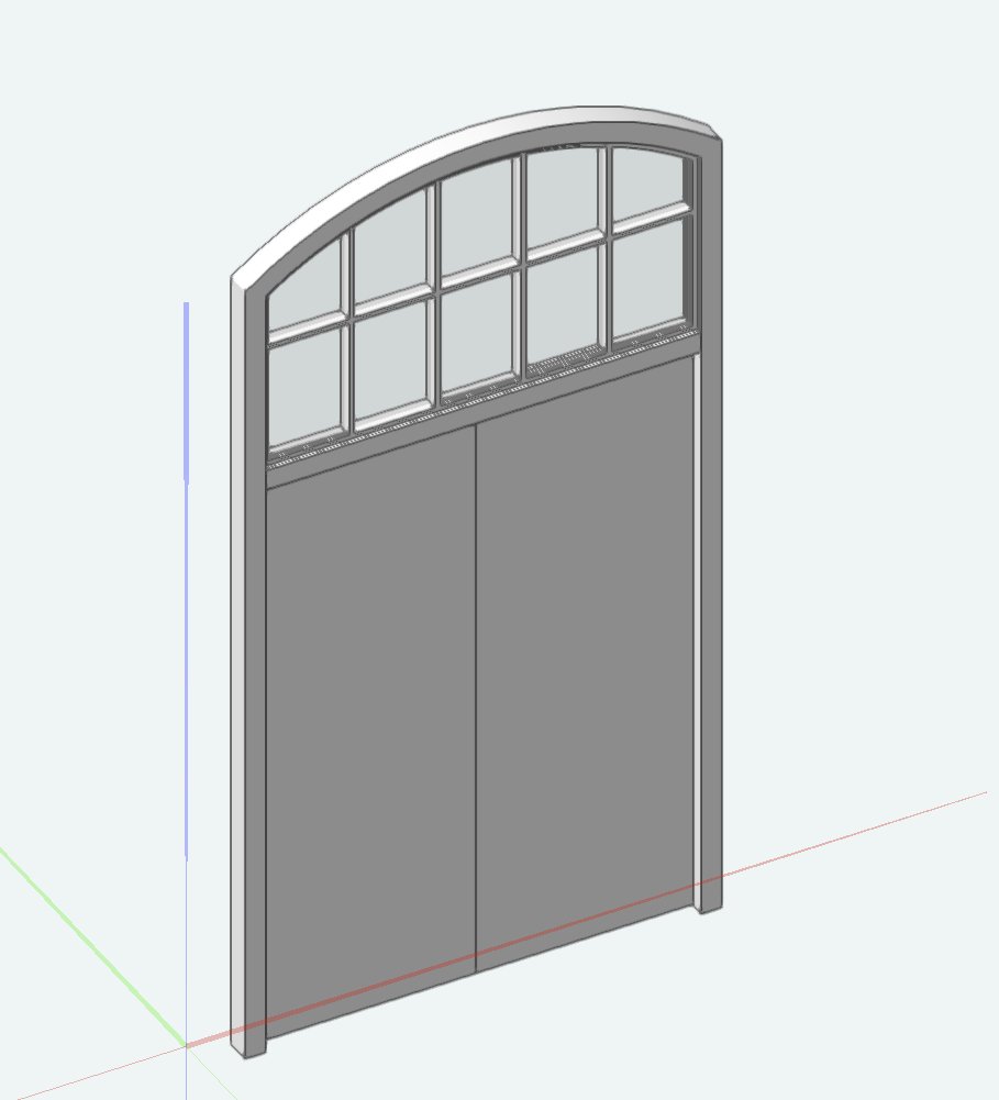

-
Parking line solid thickness
zoomer replied to Vectorworks drafter Shiv's question in Troubleshooting
Select Lines and"Create Objects from Shapes" / Walls ? Walls Style > Wall width about 10 cm, Top Bound fixed 1 cm above Wall Bottom Bound. Walls should export fine. -
Rendering with windows, doors and extruded object VW2024
zoomer replied to Catmansound's question in Troubleshooting
I think Windows and Doors got some substantial changes for VW 2024. I also experienced some strange things after migrating my VW 2023 files. Not all Doors and Windows (of a same Style), but some. So after VW 2024 migration I usually do a "Reset all PIOs". -
VW2024 Doors - how to change hinge side on a swing bi-part configuration?
zoomer replied to StefanoT's question in Troubleshooting
Thank you very much again ! I was not sure if others experience the same behavior or just me. Or if it makes sense ... or so ..... (Like something with "uneven" Sash width needs to happen - if I change the mullion width ?) -
VW2024 Doors - how to change hinge side on a swing bi-part configuration?
zoomer replied to StefanoT's question in Troubleshooting
I tried a clean File from VW Blank Template, one of the default generic Wall Styles. I imported my migrated Window Style and inserted it into the Wall. Set to custom Configuration. Set 2 Columns, Double Tilt/Turn. I'll attach the test file : Untitled WIN TEST.vwx I even tried one of VW's default Library (simple custom) Window For me it does the same ...... As soon as I edit another value, uneven ratio dimension setting jumps back to default equal size. Untitled WIN TEST 2.vwx -
I had this in VW 2022 (?) since I installed it. after I downloaded nearly all of VW Libraries but moved them from System Disk/VW App Folder to my Workgroup Folder on an external disk. Either VW had a problem with moving (too much ?) objects itself or I assume it maybe could have to do with a loaded Library which is not meant for my VW Arch license type (?) or that VW got a problem to check license or file date that way. Never could get rid of it. So for following VWs I just avoided downloading their extra libraries.
-
VW2024 Doors - how to change hinge side on a swing bi-part configuration?
zoomer replied to StefanoT's question in Troubleshooting
just as a teaser so far, it seems reproducible. (did not yet try new Windows in a file from scratch) Steps : - Window in Wall - type custom - no matter if horizontal or vertical Sash group, create (min ?) two sashes - enter a custom dimension for width or height to make an uneven ratio for sashes (Maybe save and reopen settings dialog first) - edit (anything) something like new mullion width .... - Custom Sash Dimension value immediately jumps back to default even Sash ratio. (I mean it does not only happen after you close/OK the dialog, it happens immediately or at least when you confirm the new value by entering another input field) -
VW2024 Doors - how to change hinge side on a swing bi-part configuration?
zoomer replied to StefanoT's question in Troubleshooting
So far, I did open the VW 2023 file again in VW 2024 SP2 and it looks exactly the same. (all the issues I mentioned about Doors and Windows) Need to examine the File in VW 2023 .... But this and the other Door/Window things, will need some time .... until I find the time .... to ..... -
So far it is not. It is still called Screen Plane. But it is partially hidden from users now in VW templates or migrated files that do not contain Screen Plane Elements. That is what I mean by using Apples (OpenGL now deprecated ....) term. (OpenGL is still available on Mac ... just no development ... which wasn't that existing there before though ...) BTW I meant screen plane clean .....
-
Delete outside a marquee
zoomer replied to Malcolm Woodruff's question in Wishlist - Feature and Content Requests
Usually do a Marquee Selection when everything is active and editable and than just choose "Invert Selection" AFAIK you can reach that over right click option menu if things selected, at least you find it in the regular Menu / Edit (?) You can do so also to fit these objects in view for examination before really deleting. -
How to identify screen plane objects in an old file?
zoomer replied to Amanda McDermott's question in Troubleshooting
I don't think these are much of an issue. I would just care about Unified View enabled with correct Settings. I thing the only nuisance about screen plane objects is when using a 3D Iso or Perspective View and some 2D Objects will jump off ground and stick to your screen ....