line-weight
-
Posts
3,755 -
Joined
-
Last visited
Content Type
Profiles
Forums
Events
Articles
Marionette
Store
Everything posted by line-weight
-

Wall Closures - VW2024 Workflow, and transitioning files from VW2023
line-weight replied to E|FA's topic in Architecture
Yes please, if you manage it! I had to write myself fairly extensive instructions to understand & use wall closures in VW2023 and am slightly dreading the transition to VW2024. Some notes from another "real" user would likely be very helpful. In particular if they highlight all the points where something in the UI is unclear or inconsistent or misleading, because you can never get that from the official documentation. -
But using what tool? Structural member tool?
-
What type of object exactly are you trying to draw? If you are using a 2D tool it'll only draw on the layer plane unless you set a working plane, in which case it will be able to draw on that. If you are drawing a 3d object then you are not constrained in the same way.
-
How do I Make a Curved Wavy Wall (Curved in Plan and Elevation)?
line-weight replied to Jack2022's topic in Site Design
It's a shame this can't be used to define a wall's shape in elevation (rather than in plan). -
VW wrongly tells me classes are invisible when in annotation space
line-weight posted a question in Troubleshooting
When I am working in annotations space, I'll often go to the class dropdown, to choose a class to draw something in, and that class will be marked there with a X to indicate that it's invisible. However, that class is set to be visible within the viewport. I think the "invisible" marking in the dropdown is left over from what applied before I entered the annotation space - that is, the class is set to invisible in the view I happen to have of the sheet layer, before editing the viewport's annotations. When I'm working within the annotation space, surely the marks against the classes should reflect what applies to that viewport. I do need to know if I am attempting to draw something in a class that's set to invisible for that viewport, because I then have to adjust the class visibility settings for that viewport. Sometimes VW alerts me to this with a popup that asks me if I want it to turn on that class for that viewport. But I'm not sure it does this consistently. Sometimes I have to turn the class on manually. -
Walls that are below the cut on floor plans appear red
line-weight replied to Harpahei's topic in Architecture
My opinion: yes. There are pros and cons of each method (standard top/plan viewport or horizontal section viewport) and many opt to stick with standard top/plan because it suits their workflows. But I'd say horizontal section viewports are the way forward and give you more control over how things appear. Because you can ask them to section at a "real" height, you don't have to worry about fiddling with things like classes and attributes for objects below the cut plane: you simply tell VW to draw everything below the cut plane in a line type of your choice. -
window and door appearance in top plan
line-weight replied to Tatiana Petrova's topic in Architecture
It might be something to do with the interaction of line attributes associated with the wall object itself, and line attributes associated with the wall components. And it may well behave differently in VW2017 compared to 2023/2024. -
window and door appearance in top plan
line-weight replied to Tatiana Petrova's topic in Architecture
Hm. I recognise this issue, because I've come up against it in the past but can't now remember what the explanation/fix is, which is frustrating me. Can you post a copy of the file where it's happening? -
The problems I've had may or may not be buried in this thread: https://forum.vectorworks.net/index.php?/topic/66229-controlling-visibility-using-data-visualisation/page/2/
-
It's a while since I was last looking at this, but I think there is some kind of problem using this workaround, in certain situations. At this moment I can't recall what it is.
-
The inability to control visibility with datavis is its most glaring omission. There are lots of things I would use it for, but can't, because of this.
-
Yes!
- 99 replies
-
- 2
-

-
- vectorworks 2024
- new ui
- (and 1 more)
-
Assume it's because it's importing everything as a mesh-like group of 3d faces, and top/plan displays those kinds of objects in wireframe. VW doesn't know it's looking at walls or floors and top/plan only really works with objects that are programmed with a 2d representation for top/plan. Personally I would use a horizontal section. Then you can view that geometry in hidden line. You can adjust the cut plane height depending on whether you want a plan layout or a birdseye view.
-
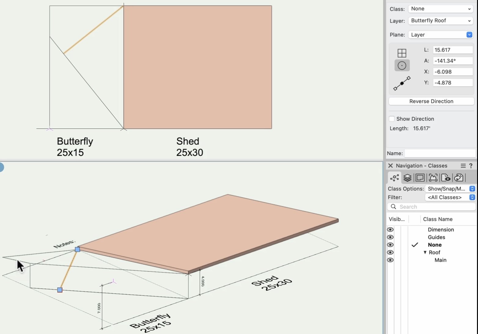
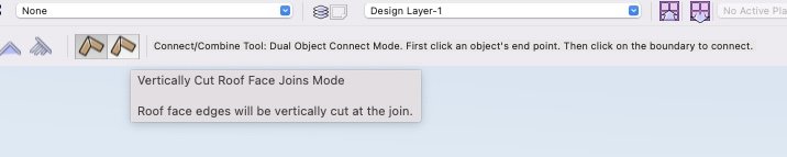
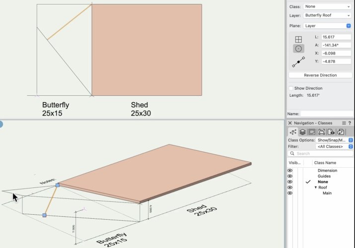
Also...regarding the "taller fascia" on the steeper sloped portion - this actually highlights a real-world construction detail question, because the fascia is not really taller. Measured perpendicular to its bottom edge it's the same height because it = the roof face thickness. The apparent discontinuity in height where the two fascia portions meet is because of the way the junction between the two roof faces is modelled (the join is projected vertically up from where the two planes meet). When you use the connect/combine tool to join roof faces you're given the option of how this join is made - vertically or mitred: This requires a bit of careful thought if you are modelling something in any detail (aside from the fact that the connect/combine tool is rather temperamental) because doing vertical joins is kind of easier to keep track of but doesn't reflect the reality of what's going to happen in most real world multi-layer roof buildups. Essentially you need to decide what's going to be the "reference plane" for the roof (I'd say you should have in mind what makes sense for the person building it - so it might be the top-of-joist plane) and then let the geometry work out from there. In many cases the actual "valley" in the roof surface will not be vertically above the join between the roof reference planes. And it can all get rather tricky if you want to set things out so that the valley ends up in a particular place...
-
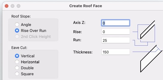
I think there are some unnecessary steps after you get to this point: Because you can specify the roof pitch by "rise over run" - you don't need to measure the pitch angle. At this stage you already know the length of that line (the run), and you know what the rise needs to be along its length (4.000 in the example).
-
@Ed Wachter I have some similar experiences to you. Certainly isolating geometry can help in many situations. Beware in particular of wall or slab objects which are not visible due to their component classes all being switched off, but which can interfere in a major way with things like acquiring snaps or push-pull faces. I think this is a bug present in 2023 but hopefully fixed in 2024 (have not yet tried). You might find some of the comments posted in this thread useful: https://forum.vectorworks.net/index.php?/topic/112507-should-vw-be-finding-me-a-45-degree-line-here/ I have picked up a few tips given in that thread ... but it remains the case that I don't always feel fully in control of what's going on with snaps etc. There's only so many shortcut keys and so on that my brain can reliably keep in its memory. One thing that improved my life recently was realising that I could use the "move by points" tool in many situations where I was previously just trying to drag objects by grabbing them with the selection tool. The "move by points" method makes it easier to find snap points.
-
It looks a bit like it is not exporting lineweights correctly. I wondered if it was something to do with having "zoom line thickness" on or off when viewing your sheet layer, but I think that would only make sense the other way around (PDF comes out with thicker lines than appear when you look at your sheet layer).
-
The issue discussed in this thread is not surface fighting, although it has a very similar appearance. Surface fighting will usually be visible in both orthogonal & perspective view I think. However this separate issue was only a problem in perspective view. But it was largely fixed (at least as far as I know) a few releases back. I currently use 2023 without experiencing it.
-
Publish to pdf results in large file size
line-weight replied to taliho's topic in General Discussion
Also when a large image file is scaled down in a viewport, VW somehow still includes the whole of the original file in the pdf. If you manually adjust the resolution of the image in the viewport this can reduce the pdf size. But it's really stupid that we should have to do this manually. -
Publish to pdf results in large file size
line-weight replied to taliho's topic in General Discussion
"Print to pdf" can sometimes be better and it doesn't cause the colour issues I mentioned above either. However, it's not a useful alternative if you are publishing a drawing set with tens or hundreds of sheets - in that case you need to use the publish command. And if (as is sometimes the case) you want to publish each sheet as an individual file, then passing all those through a third party compression programme is rather tedious. -
Publish to pdf results in large file size
line-weight replied to taliho's topic in General Discussion
I have used other compression apps but haven't tried this one until just now. Gave it a 28MB PDF created by VW and it compressed it to 550k with no noticeable loss of quality. The fact that this is possible, to me is a clear demonstration that VW's PDF export doesn't work properly. Sort it out, VW! -
Publish to pdf results in large file size
line-weight replied to taliho's topic in General Discussion
I don't think you should rebuild your file. I don't think there's anything wrong with your file - there's something wrong with the way VW creates PDFs. You would be better investing your time in finding a PDF size reducer, for example the one recommended by @Christiaan above. Because you will likely have this problem with most VW files. -
This thread (note most recent addition to it) illustrates why reliance on an exporting-the-model workflow makes me nervous.
-
Publish to pdf results in large file size
line-weight replied to taliho's topic in General Discussion
Exporting to PDF is such a core part of pretty much everyone's workflow these days, it's very poor that VW show no interest in addressing this issue. There have been so many threads about this over the years. Never do I recall a response from anyone at VW acknowledging that it's even a problem. And parallel to this is the fact that publishing to PDF can mess up colours in images. -
Publish to pdf results in large file size
line-weight replied to taliho's topic in General Discussion
Excessively large PDFs has been a problem with VW for years. There was a another thread about it just yesterday. And that thread has links to other threads. https://forum.vectorworks.net/index.php?/topic/113794-pdfs-tips-for-reducing-size-scrolling-speed/#comment-494791 Maybe complain to your VW distributor. Perhaps if enough people complain about this they'll think about fixing it one day.