


Boh
-
Posts
1,704 -
Joined
-
Last visited
Content Type
Profiles
Forums
Events
Articles
Marionette
Store
Everything posted by Boh
-
I'm afraid, as far as I'm aware, all frame members are controlled by the same class.
-
Yes it's this details level setting.
-
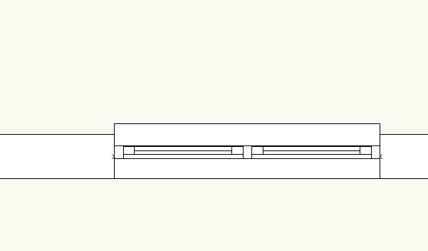
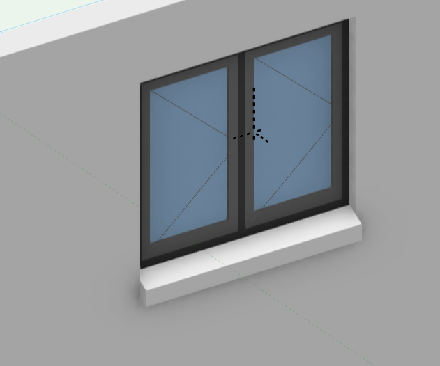
I'm not sure why the wall sill isn't showing in 2D. I thought maybe you had no sill projection but the 3d view shows there is one. I'm not having this issue. This is a Windoor on my machine: I could have a look at your file if you want to post it.
-
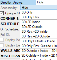
This might be the Direction Arrows setting in the OIP. In top / plan view awning windows will show up a rectangle next to the window to show where it is opening. I usually have these set to hide for 2D.
-
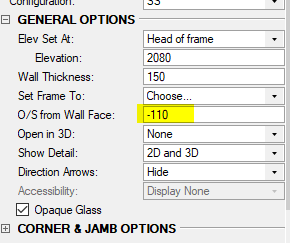
It might be the offset from wall face setting. I get a line too but it is offset 110mm which is the default O/S from Wall Face setting. You can adjust this in the OIP. What does the window look like when you put it in a wall?
-
Converting 2022 .vwx file to 2021 without access to 2022 anymore
Boh replied to SODOHO's topic in General Discussion
Hi Sarah. No I don't think you can. There is usually someone on the forum happy to help. I would be happy to do it except I haven't upgraded to 2022 yet... -
Attach record to symbol in resource manager
Boh replied to Jayme McColgan's topic in Python Scripting
You can attach a record to all the symbols in a selected RM folder via the tools menu. This will just apply the default record field data to the symbols. If you want to change the record info for these symbols from the default you need to right click on a symbol in the rm and select “attach record”. Select the record and click on the edit fields button. -
You can’t lock classes but you can lock any object. I have my slabs on the same layer as my walls and often lock the slab so they don’t move accidentally. It also means you can select all and “move to front” and the locked slab will stay behind everything else, just where you want it.
-
I don’t have vw2022 but in 2021 this problem is usually solved by turning on unified view in the view menu.
-
I found the RM worked a lot quicker when I removed all those nice to have favorites files located on a server.
-
Hey Federico. You can edit the notes via the keynote legend. Double click on a keynote legend and there is an option to edit the notes. This will edit all duplicates instances of the same note linked to that legend. Also, in vw 2021 and vw2022 the notes manager has been developed a bit so that when you edit a keynote callout vw should ask you if you want to update all instances of the same note as well asking you if you want to update the note in the database it is linked to. The notes need to be linked to a database for this to work. I'm not sure what best practice is here. I have a "Master Notes" database from which I take a lot of notes from but then usually edit the notes to suit the project I'm working on and then add the notes to a project specific notes database. That way as I go around and annotate my drawing I can quickly add the revised notes to the drawings. I make sure all keynotes are linked to the database so that if I update one, all of the duplicates will update with it.
-
The legend is listing all the keynotes that have been assigned to it. To remove a keynote from a legend you need to find the keynote and either delete it, assign it to anther legend, or turn it into a normal callout. If the keynotes have duplicate copies assigned to the same legend then you need to find all the duplicates.
-
Another, possibly better, but with it's own limitations, technique to repeat geometry over a number of levels in a multi story building is to use design layer viewports instead of symbols. I have used this successfully and haven't had the issues with wall heights. To do this you create a "base plan" and then create dlvp's of it, one for each repeating level. I would suggest putting each dlvp on it's own design layer and use the design layer elevation to control the height of the geometry so that the z height of the actual dlvp can stay at 0 in relation to it's dl. Ask for more detail if you are interested in trying this out. Cheers
-
Yes the section line itself has to be the same for every defining section line. Ive used the data tag technique where I wanted to have the marker off the line due to crowded annotations so haven’t had to fiddle either the line I agree with you re viewport naming. Vw should have a better way of naming vps that use the sheet no, drawing number and drawing title. I rely heavily on a script to rename vps for the very reasons you outlined in you post above..
-
When you say “link” I think you are talking about section elevation lines which “define” section vps. Ie the line length and location defines where the section cut is made. VW uses the term “link” where a section line is simply linked to the section vps sheet and drawing numbers. Ie moving the section line has no impact on the section vp. If you draw a section line and instead of creating a vp from it, where the section line will then “define the vp”, you can instead just link it to an existing vp. So for question 1 I don’t think you can “undefine” a section line from a vp but instead of ungrouping it you can trace another section line over it an in the oip and just “link” it to the section vp. Then delete the original section line. The linked line and markers can be moved around without changing the vp. For question 2. Yes the section line markers will all be in the same place for section lines which “define” a section vp. If you want section markers in different spots you could do what I suggested for question 1. Another option which I have used, and which might answer your follow up issue is to use a section elevation line style that has no markers, then use data tags as markers. Then only the section line itself will define the vp but the marker tags can be anywhere you want.
-
I can't find a way which makes me wonder what the "Standards" folder is for specifically? The other folders contain default content that various tools can draw on. What tool uses the Standards folder?
-
This is what I do and it's a great way to keep your class standards tidy. You could create a symbol with geometry in the new classes and export the symbol to the standards file. With a create symbol shortcut key it've very quick to turn a line into a symbol>locate symbol in RM>Export. Yes it would bring the classes in but, and I need to check, maybe not any hatches, textures etc associated with that class unless the wall used class attributes.
-
duplicate an object does offset the duplicate?
Boh replied to KingChaos's question in Troubleshooting
Tools>Preferences Might be in the display tab. It’s a n there somewhere… -
Section VP of a DLVP : Objects Beyond Cut Plane vanish.
Boh replied to Stéphane's question in Troubleshooting
I have encountered other bugs sections through DLVPs. I’m not sure if this is a bug though. Can you post or pm me the file? -
Yes! I've done that too and created a whole bunch of custom selection scripts for various common objects like lines, circles, spaces, text, etc etc and made them all commands in custom menus. Another advantage of making them commands over resource scripts is that scripts in the RM are file specific whereas commands are available to use on any file. One thing I do like with palettes though is that you can have them right next to where you are workin,g which is what I do when I am using them a lot, and when finished you can switch them off. I have a bunch of scripts in custom palettes in our drawing template files. Thanks for the reminder about the quick search function. TBH I had totally forgotten about both that and the smart options display. I'll have to try and start using them in my daily workflow.
-
Yes quick ways to do repetitive tasks are definitely worth the time to set up! There are at least a few ways to make scripts in VW without having to know how to actually write them. When you make the script you need to stick them in a palette. If you don't have any custom palettes then VW will ask you to make one. I've made a few scripts to place objects in certain classes. This is one which will place selected objects into the "None" class. To customise it for other classes you just need to replace "None" to "Whatever is the name of the class you want to place the objects in". Procedure SetTheClass; CONST kCName = 'None'; VAR gh1 : HANDLE; Function DoIt(h1 : HANDLE) : BOOLEAN; BEGIN SetClassN(h1, kCName, True); END; BEGIN Locus(0, 0); gh1 := LNewObj; ForEachObjectInList(DoIt, 2, 2, FInGroup(GetParent(gh1))); DelObject(gh1); END; Run(SetTheClass); I You can use quick search toggle custom script palettes on and off. You would still need to click on the script you want. Hope this is helpful in your efficiency drive!
-
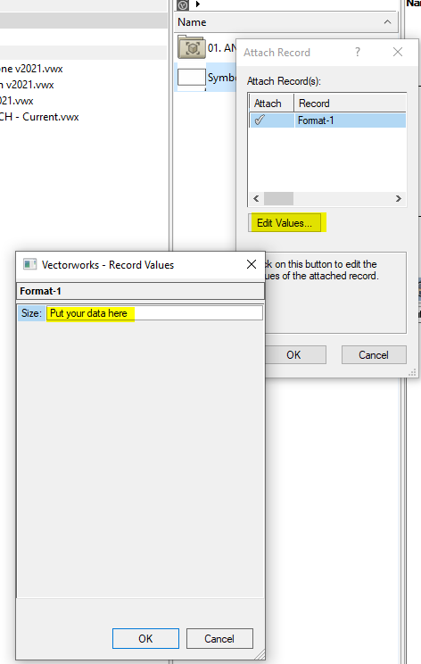
Once you get to the "Attach Record" dialogue, as described above, put a tick next to the record you want to attach and with that record selected hit "Edit values" The data you input will now replace the default record field data and will be inserted into the file with the symbol.
-
Not sure I understand what’s going on but I think you either need to make sure when you place a symbol you are getting it from the active file not the version in the workgroup which doesn’t have the updated record info. Or you’ve only edited the record info attached to symbol instances not the symbol definition. If you edit the info to the definition then it will be attached to the symbol when you insert it in your dwg. To edit or add info to the definitions right click the symbol in the RM and select “attach record”.
-
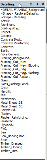
This one is handy as it saves a lot of scrolling through the class drop down list in the oip. Another trick is to use scripts. I have some for commonly used classes that simply place the selected object in a specified class. Then there is also the custom tools command where you can create scripts to draw an objects and also have them placed in specified classes. Below is a bunch of scripts I created for drawing 2d details. All the objects take on the class attributes so it makes drawing details very quick.
-
I use the eye dropper tool all the time for changing an object’s class. There just needs to be another object nearby already in the reqd class. I’ve even changed the shortcut key for it to ‘E’. Another way is in the nav palette. Right click on the class and select “assign to selection”.
