Boh
-
Posts
1,704 -
Joined
-
Last visited
Content Type
Profiles
Forums
Events
Articles
Marionette
Store
Everything posted by Boh
-
Yes this is a tricky situation where you have a single tall building element passing through multiple layer elevations requiring a different 2d plan representation on each level but also requiring a homogenous 3d representation for live sections & elevations and perspective views. This happens with things like downpipes, curtain wall glazing and ramps. As Lineweight has said there isn't a way to model it where a single object can serve satisfactorily for each of these different views. The only way I've found is to create a hybrid symbol which has within it separate 3d & 2d top/plan representations. (I understand VW 2019 has developed this further so that hybrid symbols also have separate 2d elevation representations though I haven't used that yet). It is still drawing 2d & 3d separately but at least it is all contained in the one object. To do this: Create the whole chimney as a single solid 3d object. Place the chimney object in the "Chimney_Elevation_Object" class. Turn it into a symbol. Double click the symbol to edit it and overlay 2d representations of what you want the chimney to look like in top/plan view on both the ground floor and the first floor. Class the 2d linework into something like "Chimney_Plan_Ground" and "Chimney _Plan_First" Place the 2d linework on the screen plane. Now when you exit the symbol edit mode it will have become a hybrid symbol so that only the 3d elements are visible in 3d views and similarly for the 2d portions. Place the symbol in your model, perhaps on a dedicated layer just for the chimney and adjust layer, class visibilities to suit the viewport(s) as needed. Alternately you could place the chimney symbol on both ground floor and first floor design layers (adjusting the symbol's z height as required for the first floor layer) so that in elevation views there would actually be two chimneys but you would only see one as they would be exactly on top of each other. Hope that helps
-
I think this is the way to go except make the other chimney parts solid objects (rahter than wall objects) then you can select the whole chimney, right click and "add solids" which will make the whole chimney a "solid addition" and it will remove the unwanted lines. You can still double click on the chimney to enter the addition and edit it later on.
-
For space tags you can have multiple size text in the tag classed for different scales and linked to the same record. e.g. the "name" record could have a 14pt & a 28pt text linked to it and classed to "Space-Name 1:50" & "Space-Name 1:100" classes and then adjust VP visibilities to suit the VP scale. For windows & doors it's a bit trickier. I don't use the Native VW window & Door tool, instead the OzCad WinDoor tool but it sounds like the same problem. This thread might have some pointers: Also I think data tags in VW2019 are more flexible and can be used for windows and doors but haven't stated using it yet.
-
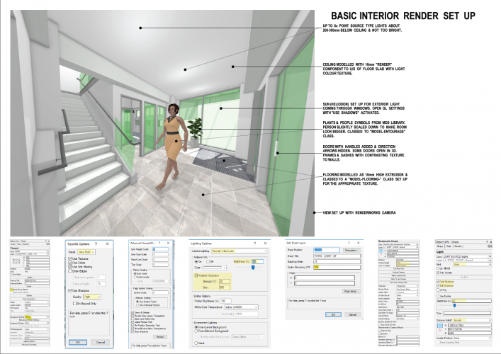
Hey I'd really appreciate some feedback on this one if anyone has some time. Renderings are one of the things I struggle with in vectorworks and I'd really like to get a workflow that gives the best possible result without blowing the time allocated to do it. This took me most of the day and it's an average render, I'd like to have a set up where I can produce better renders quicker. Any good advice I will update to this PDF and reshare on the forum for others to use. thanks.
-
make all textures the same button
Boh replied to lupin's question in Wishlist - Feature and Content Requests
Yes. Definitely gets my vote! -
Site Model - What is the Best Way to Set the Elevation?
Boh replied to mgries's topic in Architecture
That's the way I do it too, however f,just note that for a recent new house on a sloping site we viewported the site design layer into the house floor plan rather than the other way around. That way, to tweak the siting of the house, we just move the Site DLVP around and our ground lines auto update on our house elevations & sections. -
Hi Our office needs to be able to produce quick and simple renderings of interior spaces occasionally for clients. We were previously using Sketch up but are now moving to using vectorworks for not just plans & details but also our 3d images. I'm not a renderworks expert but have managed to come up with a workflow and a bunch of settings that produce reasonable images - no need to be photo realistic here. I threw together a pdf as a reference document for our office of the basic sheet, viewport, lighting settings etc so we don't have to recreate the wheel everytime we do this. I'd appreciate it if anyone cares to check through the settings on the attached and provide any feedback that would improve the images produced without increasing time spent disproportionately - i.e. bang for buck is the top priority! We are currently using VW2018. Thanks!
-
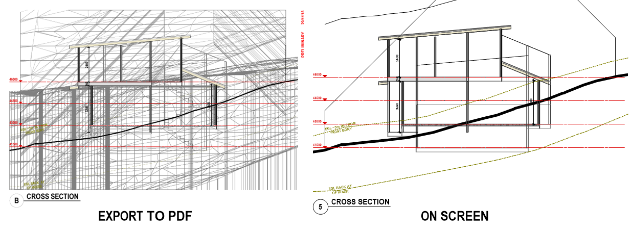
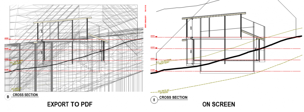
When I export my cross sections to pdf the extents before & after the cut plane of objects in a DLVP are exported even though they are not displayed on the screen. Anyone know what is going on? Just started using VW2019 SP1.1.
-
Not quite mate!
-
Not on my version! It seemed to be working ok on Wednesday. Thursday some 3d locii showing in 3d views, others not. Haven't got 2019SP2 yet.
-
Have just started using VW2019, have literally just updated to SP1.1 (latest SP available where I am). The "Simplify Polygon" command is mixed up. to activate it I have to choose the adjacent "Validate 3d data" command on the AEC menu. Haven't yet worked out howto "Validate 3d Data". hopefully won't have to. Does anyone know if this is a known bug? Are there more of these command mix ups? Can I fix it? Thanks
-
I don't suppose putting the worksheet inside a viewport and then using the VP visibility controls would control the class visibilities of images in the worksheet?
-
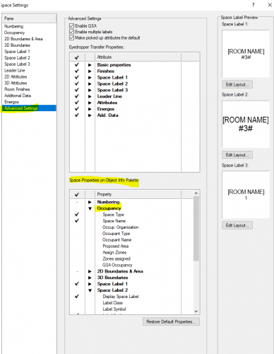
Assuming these are on a design layer then maybe try copying everything on that design layer into a new blank file along with the worksheet and then recalculate the worksheet in the new file to see if the anomaly reappears? If not delete the oringinal DL and reimport the new file design layer. If it does reappear then you could gradually start stripping out everything in the new file design layer, recalculating the worksheet as you go to see if you can corner the offending items. Have you tried editing the numbers directly in the actual worksheet? This is one of the big plusses of how a two way worksheet operates. That said, some data fields may not have this capability so yes you would then need to edit the actual object. You can change what space info appears in the OIP via the "advanced " tab of the space object dialogue. I'm not an expert on this but I would say it is probably due for a clean out...
-
Good points Line-weight. Our local council has also finally started taking electronic building consent applications too so now there really is not much reason to stick to A1 format. We are about to upgrade to vw2019 in our office after the xmas break and we'll also start using the native VW Title blocks so that we'll likely make the change to A3 then.
-
I think the "Custom Stair Tool" is now a legacy tool, (i.e. no further development). There has been a lot of discussion on the forum about improving the "Stair Tool" however and there were some improvements in 2019 as I understand things.
-
You could add a couple of extra columns with "=L" & "=C" in the database headers so you can narrow down what class and layer the spaces are on. Other than that I think we would need to see the file to see what is going on. What are the columns in your image? areas? and?
-
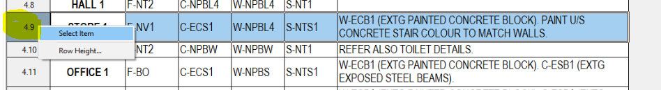
In the works sheet, if you right click on the row header you get a pop up menu. Go "select item" and it should take you to the space object you are trying to find.
-
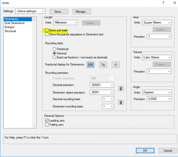
Hi Sandra. Go to File>Documents Settings>Units> and uncheck "show unit mark". Hope that works.
-
Edit Symbol in Viewport Annotation Show other Objects
Boh replied to John Meunier's topic in General Discussion
I just had a quick play with settings and couldn't find a way to do it. -
Like you Andrew we also mostly print to A3. We have set up our pages for A1 (with 50% reduction for printing). This is means we have set up a large 14pt standard text size for A1 that is still readable in A3. So text in any symbols throughout our library are typ set to this font. We are using PCs which, when set up for 50% reduction in the printer set up can mean hatches sometimes don’t scale correctly. I don’t think this is an issue on Macs. Srtting up for A1 and printing at A3 does give a little more printable area than setting up straight for A3. we are considering moving to an A3 set up so interested in other thoughts. For renders and presentation drawings as opposed to construction detail drawings we will sometimes set up straight to A3.
-
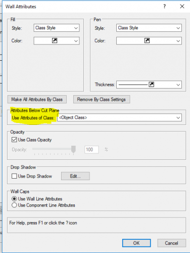
Does editing the wall style help with image 2?
-
Occasionally symbols may contain some information on "NonPlot" classes which you wouldn't want to see in the worksheet image, so this is a good reason for the images classes visibilities to be controlled through the current class visibilities. What about putting the worksheets inside a viewport and having the viewport visibilities control the image classes?
-
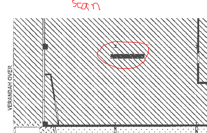
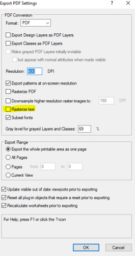
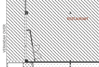
Haven't used pattern fills much, thought I'd try them. Looks great on the screen in vectorworks, also looks great when exported to pdf, but when I print the pdf it messes up any overlaid text. This is a scan of a printed hardcopy: This is what it should look like: I've discovered that if I have "Rasterise text" checked" in the export pdf dialogue then this sorts out this little problem. The next question is how do I make this the default PDF export option so I don't have to remember to have adjust this setting everytime I export? Thanks in advance!
-
Maybe I've misunderstood but, in the criteria dialogue can you not just keep adding an additional choice for each layer for which you want to select objects? I thought that if the object criteria are mutually exclusive then it will select objects that conform to both criteria - an "or" scenario (in this case layers). If the criteria is not mutually exclusive then it is an "and" scenario, i.e. only objects that conform to all criteria are selected.
-
Cool thanks.