
Andy Broomell
-
Posts
3,178 -
Joined
-
Last visited
Content Type
Profiles
Forums
Events
Articles
Marionette
Store
Everything posted by Andy Broomell
-
BTW - the tricky thing about that OpenGL quality level is that it's a setting that saves into Saved Views, meaning if you already have a bunch of saved views, then increase your quality setting, then run one of your Saved Views, it will revert back to the lower quality. I recommend making sure your blank template has it set to High so that it's never an issue on future projects. (I also like to turn on OpenGL edges and Ambient Occlusion under lighting options).
-

My wish: VW2021 to have no new features. Please.
Andy Broomell replied to line-weight's question in Wishlist - Feature and Content Requests
@line-weightYour two posts above perfectly encapsulate many of my views on things like 2D vs 3D, my frustrations involving the two, and how we 'make it work'. I design almost entirely in 3D, but still need to produce 2D drawings (which isn't going away in my industry any time soon, nor do I think it should). Both 2D and 3D both have very legitimate places within my workflow. I think that the integration between 2D and 3D is one of Vectorworks' strengths and a major selling point compared to other programs; I simultaneously feel that it is one of its weakest points that needs way more attention as it relates to actual workflows. While these seem to be contradictory statements, both are true. Over time I've thankfully become intimately familiar with many of Vectorworks' idiosyncrasies related to the above, involving numerous workarounds and manual fixes... weird Section Viewports, converting copies to lines, plane issues, and so forth. While in many ways I've "adapted" to these idiosyncrasies, I see less experienced users hitting roadblocks in the program which makes me realize how much easier and more intuitive many aspects should be. Posting on the forum is helpful, of course! We all continue adding our thoughts about what's good and what's not-so-good (although sometimes it's difficult to clearly explain what the underlying problem might be - there are a few issues I feel apathetic about even attempting to explain). I almost wish I could just record a day of me working in Vectorworks to help show the program's engineers what's actually involved in one user's real-world use. It's all the little things that add up to our frustration. But I also know that my frustration arises from my love for the program and all the things it allows me to do (not the least of which is to provide me a steady income). I just hope 2018 includes mostly fixes and improvements to existing elements. Brand new tools are great, but I find myself barely using them compared to the bread and butter of the program. -
This might not be related to your particular case, but double check under View < Rendering < OpenGL Options that your "Detail" is set to at least "High" if not "Very High".
-
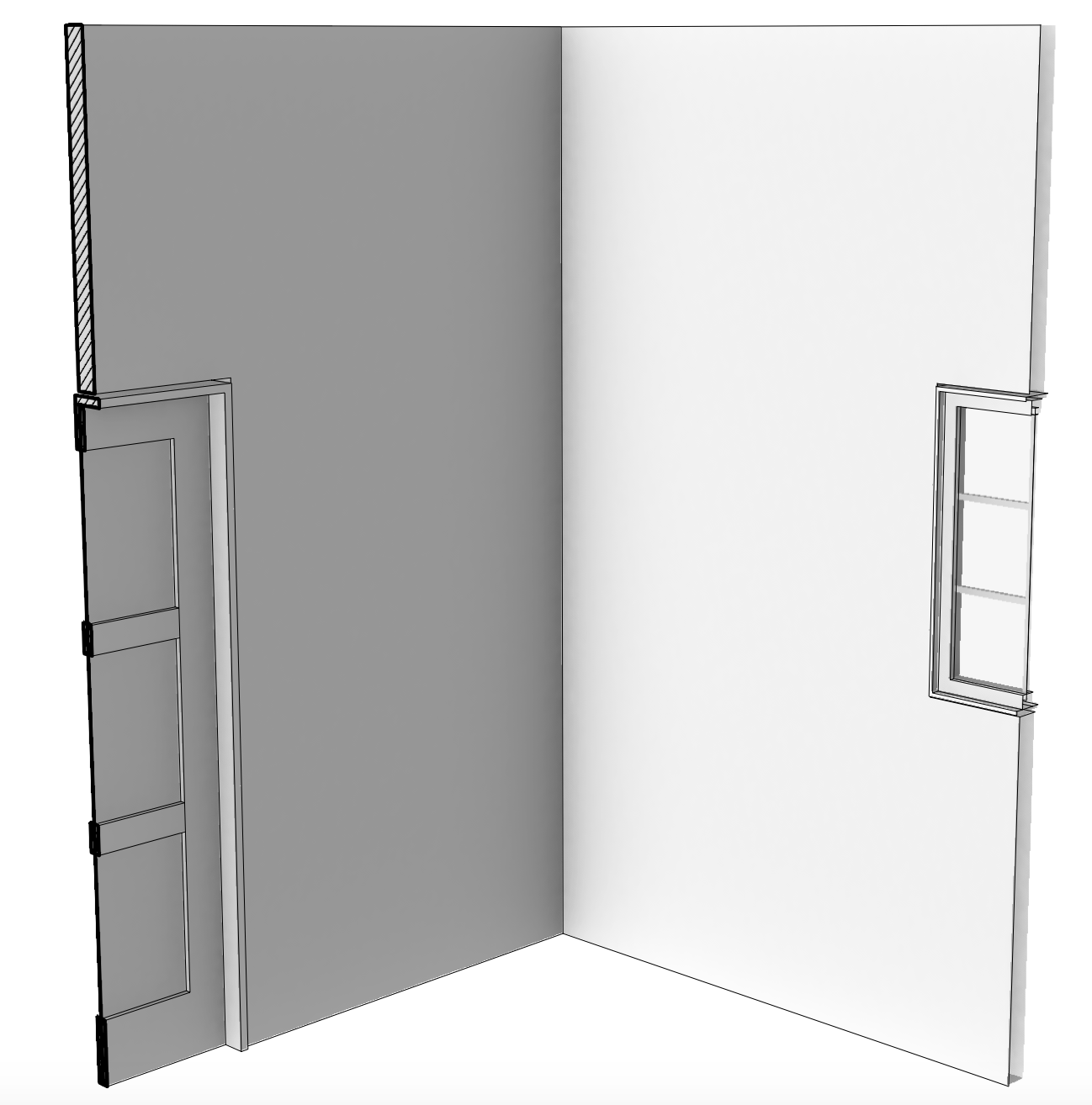
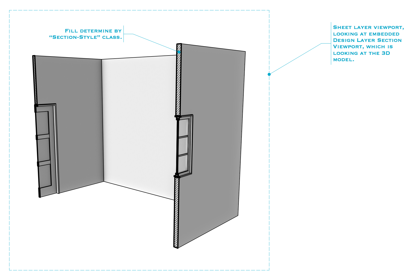
This is effectively true. While you can cut away on a second plane by setting Length Range to "Limited by Section Line Length" (and positioning the section line accordingly), the cut plane of that second cut doesn't received the Section Style fill:

-
It is possible! Not super intuitive, but possible. See the attached file at the bottom of the post for how to set it up. Screenshot: Perspective Section.vwx

-
I often use the Visibility Tool (hotkey "V") to quickly turn off a class by clicking on an object which is on that class. It's an easy, interactive way to hide things I don't want to see. As you hover over an object with this tool, it preview highlights in red all the objects on that same class. If I have a large, complicated file, there are bound to be many things on the None class, and if I happen to hover over something on the None, the tool stalls for a while as it tries to interactively highlight every single object on the None class, including things inside groups & symbols. It then stalls a while longer as it tries to de-highlight everything upon moving the cursor away. Because of this, the Visibility tool essentially becomes unusable in large complex files (which ironically is when it's the most useful). It'd be great to have the option for this tool to ignore the None class, because not only is the stalling quite disruptive (and looks bad when in the middle of screen sharing), but I never intend turn off the None class in the first place. I don't want to accidentally turn it off with the Visibility tool. There's already a settings button for this tool - so this improvement could simply be a checkbox added in that pop-up which says "Ignore None class".
-
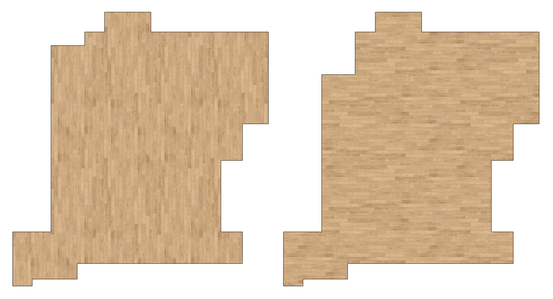
What exactly determines default texture direction in an Extrude? I ask because we almost had a bit of a disaster when an revised flooring plan was sent out to our flooring people, but showed the planks rotated 90° from what they should be. I've pulled out the shape into its own file and attached it. Here's a screenshot of the shape before and after: The floor shape had been modified in Top/Plan in a Design Layer (where it's easy to not think about textures). The Viewport for the flooring plan is in OpenGL. All that was modified was moving the edge in the upper left corner using the Reshape tool (within the Extrude). No vertices were added or subtracted, only the one edge was moved parallel to where it was. This should not cause the direction of the texture to change. This almost screwed us, but thankfully an attentive eye on the flooring team asked "Was this intentionally changed from what it was previously?" before installing the flooring onto the set. I should also note that I'm working on a television show, and changes are made constantly and very quickly / on the fly. There's not a lot of time to triple check everything. One should be able to assume that moving one edge slightly shouldn't cause any other changes except for that one moved edge. Any info about the underlying cause of the texture flip? FlooringTextureDirection.vwx

-
Separation Lines in ClipCube
Andy Broomell posted a question in Wishlist - Feature and Content Requests
Similar to my request here, I want to be able to see the lines between objects that are being cut through by the ClipCube. For example instead of this: I'd love to see this: This would be much more informational and helpful to me. It should probably be an option that can be turned on and off, because I'm sure there are times when the current method is preferable.
-
But what about a Renderworks Style that's set to Artistic?

-
Messing around with the Lines and Shadow artistic render style... Is there a way to control the quality of curved things? See the shadows in the lower part of the screenshot below (OpenGL on top, Artistic RW on bottom).

-
Class cursor position
Andy Broomell replied to Pierluigi Feltri's question in Wishlist - Feature and Content Requests
In one sense I completely agree, and in another I wonder how to keep the "New Class/Layer" handy because I use that ALL the time. -
Line Type/Dash Style/Line Style Scaling
Andy Broomell replied to Gonda's topic in General Discussion
To clarify this a bit (because the "New Line Type" dialogue box is admittedly a little unclear) the two varieties of Line Types are "Simple" and "Complex." Simple: These are the old-fashioned ones, based on the line length and gap length. Most of the default linetypes are this variety, and distances can only be page-based. Complex: These are the ones that can be made up of other geometry, and can be page-based or world-based. Looking at the dialogue box, it's either the upper portion or the lower portion. But at first glance it appears that "page-based" and "world-based" are just options related to creating lines with the upper visual interface. But in fact, you're either choosing Simple by using upper portion, or Complex by using the lower portion (along with pre-determining whether its page- or world-based before drawing the geometry in the subsequent interface). All that being said, I don't know of any way to make a line-type be screen scale, unfortunately.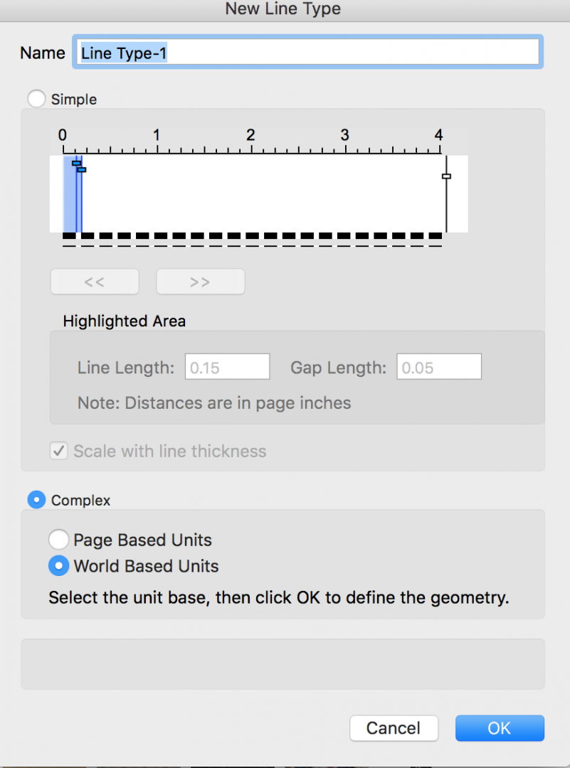
-
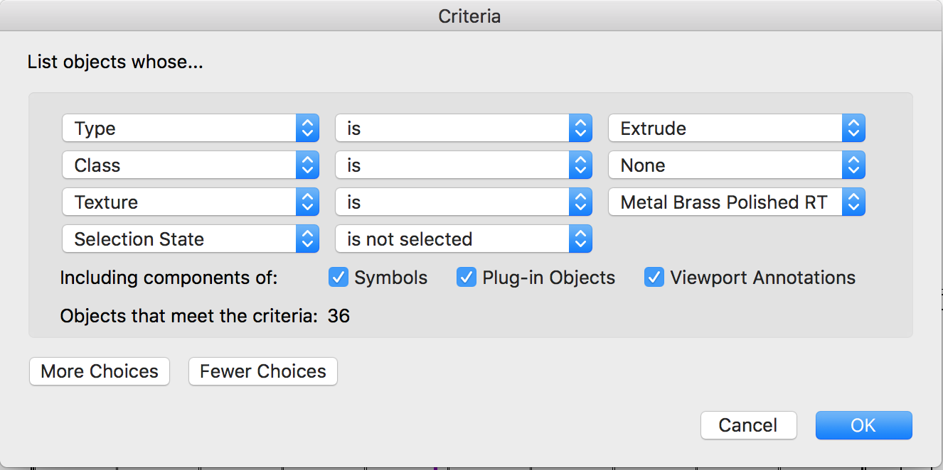
Additionally, any place in Vectorworks where additional criteria are defined with "More Choices" and "Fewer Choices" buttons, there needs to be a way to delete individual criteria lines, instead of only being able to use "Fewer Choices" to delete the last line. For example, if I wanted to delete the "Type" criterion below (in order to then include all 3D objects such as Solid Additions, Sweeps, etc.), I'd have to delete all of the other criteria first, then recreate them. Instead, there should just be a little minus button in front of each line for quick and easy removal of unwanted criteria.
-
Cool - I hadn't seen that other thread! I do hope that multi-pass rendering is eventually implemented into Vectorworks.
-
Good idea! Photoshop would allow you to do many things to the AO, such as remove unwanted areas, alter its graininess, or even change its hue for some interesting effects. Regarding graininess of AO within Vectorworks itself, I believe that's controlled by the anti-alias quality setting of the render style.
-
Beautiful!
-
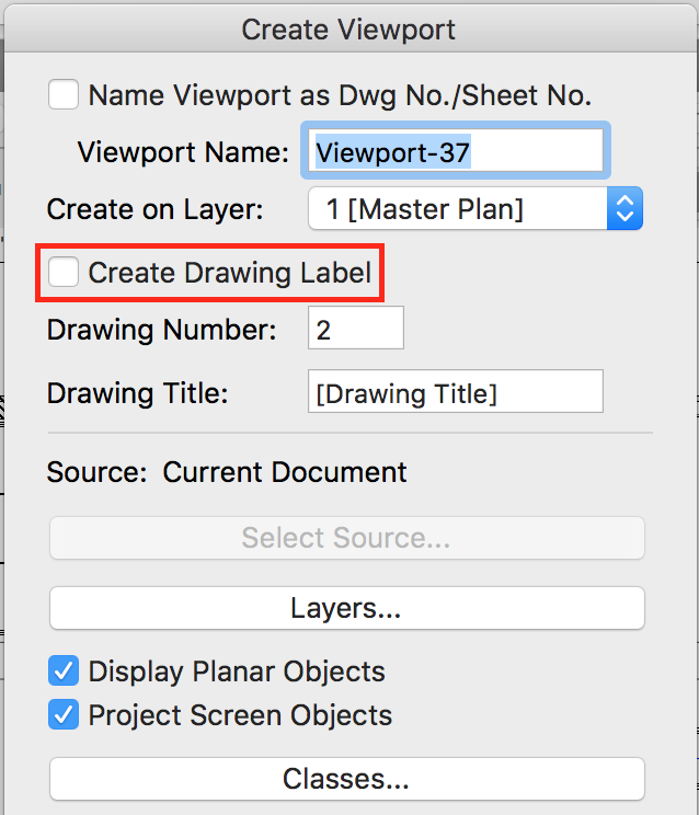
To avoid creating the label in the first place, uncheck the "Create Drawing Label" box while creating the viewport: To delete ones that have already been created, double click the Viewport and choose Annotations. (You can also right click the Viewport and go directly to "Edit Annotations"). This is where the Drawing Label objects live so you should be able to delete them this way.
-
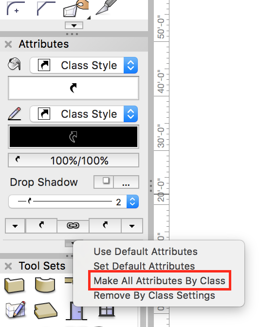
There's also a handy "Make All Attributes by Class" command in the little flyout at the bottom of the Attributes Palette.
-
Railing/Fence Tool - eyedropper doesn't work
Andy Broomell replied to Andy Broomell's question in Known Issues
Any update on this bug? Having to manually match handrail settings is a drag. -
Select the object, then in the OIP click "Plant Settings." On the "Size" tab, enter a Custom Spread and Custom Height.

-
What happens if you switch to another Workspace (under Tools<Workspaces)?
-
Extrude along path.....need help
Andy Broomell replied to Steven Kenzer's topic in General Discussion
When you do the Extrude Along Path command, make sure that the 36" circle is highlighted in red, not the 1/2" circle. Otherwise it's using the wrong circle as the path which in this case causes it to fail. EDIT: We posted at the same time. If that's not the issue, then I'm stumped! -
The records can be accessed in the Resource Manager. Make sure that your current file is selected in the lefthand column, then in the dropdown near the top make sure "All Resources" or "Record Formats" is selected. Your Record Format should show up, which you can right click and edit. By the way, after editing a field that's already attached to text in a title block, I've found that sometimes I have to go back into the title block Symbol and relink the field to the text (Tools<Records<Link Text to Record) for the change to take effect. Hypothetically you shouldn't have to do this, but it's been buggy for me before and this seems to be the fix.
-
I've wanted to do this a few times, but have never found a way. Would be a great function to add.
-
Interactive Fillet
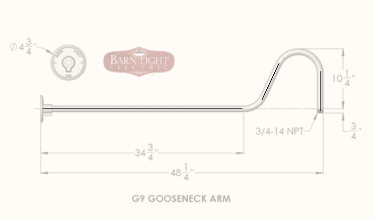
Andy Broomell replied to Andy Broomell's question in Wishlist - Feature and Content Requests
Bump. Crossing my fingers for implementation in 2018. This would be a great example of making a simple yet essential improvement to an existing tool that people use every day. It would save lots of time and headache. Here's a quick example of how this would be useful. Below, I'm tracing the simple shape of this gooseneck light arm. After drawing the three straight lines, I need to connect them using the fillet tool. Ideally I could just click two of the lines then drag the mouse to interactively set the size of the fillet. However, it only works by typing in the fillet radius ahead of time, but I have no clue what that number is. So I first grab the arc tool and draw an arc approximating the curve (the problem being that it's impossible to get the arc perfectly tangent to both lines). This allows me to see the radius in the Arc's OIP. Then I delete the arc, go back to the fillet tool, type in that radius, and finally create my actual curve. This should be a much simpler process.