
Sam Jones
-
Posts
1,191 -
Joined
-
Last visited
Content Type
Profiles
Forums
Events
Articles
Marionette
Store
Everything posted by Sam Jones
-
You will have to make a vectorscript command. You can do this with the custom selection tool. OR Put the attached file somewhere on your hard disk and double click on it. OR Use the plug-in manager to create a command called "Select all Legacy Hoists". When you edit the script, place the following line in the text window: SelectObj(((R IN ['HoistVW']))); and save the command. You can then put that command into your workspace in any menu that you specify. Why are the new hoists the way they are is above my pay grade. If you want help with any of the above, contact me. Sam Samuel L. Jones Developer of AutoPlot Tools for SpotLight, and AP Cable Tools E-mail: sjones@autoplotvw.com (310) 993-4172 (cell) Select All Legacy Hoists.vs
-

create and insert folder into preexisting folder.
Sam Jones replied to Jayme McColgan's topic in Python Scripting
What you need to do is make the new folder in its final destination by specifying that path when you call the CreateFolder() function, then move the newly created symbols into that folder by specifying its path. I do this with 7 different routines. If you specify a path and folder that already exists, no new folder is created, and the newly created symbols are placed in the existing folder. -
Let us know if Lightning Tapes got back to you. Their website says they have suspended registrations.
-
I have created and am good with event enabled point objects and path objects. Is anyone willing to share a tool template, or instruction on the difference between an event enabled PIO tool and an event enabled PIO object. It seems likely that tools are not event enabled, since they do not persist, but a simple example would be good. TIA, Sam
-
What version of Vectorworks Spotlight are you using?
-
New options in script parameters...how to use them?
Sam Jones replied to SamIWas's topic in Vectorscript
Pat - Thank you. Kevin - ?? -
New options in script parameters...how to use them?
Sam Jones replied to SamIWas's topic in Vectorscript
I didn't understand any of that. Is there a kindergarten version explanation? -
You might try using "Inst Type" instead of "Instrument Type". "Inst Type" is the worksheet or universal name for that parameter. Just a thought; I haven't tried it.
-
Happens to me too, Pat, but I've just been playing around with Truss, Hoists, and Hanging Positions. I will be curious if any source of the problem you find might not be dependent on the tagged object. I would send you an example, but I deleted them as they occurred and moved on; I thought I might be doing something wrong.
-
Cool. I'm looking forward to checking them out.
- 3 replies
-
- 1
-

-
- worksheets
- order
- (and 2 more)
-
Label Legends / Schematic Views / Sidearms together
Sam Jones replied to Bri's topic in Entertainment
Me too please. -
This also happens to me. I wish I could find out what is causing it. I have found that nudging the selected object up and down will restore the OIP.
-
Hoist Tool 2021 & Up Proper Weight Field & Format
Sam Jones replied to MattG's topic in Entertainment
Matt, The new hoist is confusing in the extreme. None of the parameters can be viewed with the plug-In manager, but, as you have seen, they can be listed when you create a worksheet of the Hoist PIO. The universal name of the new Hoist PIO is BrxHoist. I have written a script that collects all of the parameters of a selected object and writes them to a worksheet. Below is an image of all the weight and weight related fields that I could find. I will be referencing the column A names. You will notice that "WeightWithChain" comes in formatted as a dimension. It does that both in the vectorscript and the worksheet database. As a result I have no idea what that number actually represents. I have written another script that collects the weights of all selected objects (of any kind) and lists them in a worksheet and totals them. For the BrxHoist, I use the "WeightWithChain_formated" field. I parse the units being used "lb" or "kg" and convert to kg and lb as needed. I haven't tested, but I suspect that metric drawings are formatted in "kg" and imperial drawings are formatted in "lb". But this needs to be tested. My script doesn't care since it will take whatever comes in (kg or lb) and convert to the other. Hopefully, VW will come back with an explanation of all weight relevant BrxHoist parameters, but until then good luck with your worksheets. If you are interested in the "Collect and Total Weight" command it is part of the latest AutoPlot Tools for Spotlight upload, 6/17/21. Which is fully functional for 2 months without registering.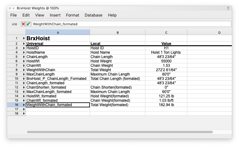
-
Thank you Josh! I've used waldo before, and I'm embarrassed that I did not think of it, but it is a different application from my previous ones. The use of "PrevSObj()" is fabulous, very scalable and applicable for the vast majority of my needs.
-
I want to get a handle to a selected object that is inside a group. In particular, I want to get this handle while I am inside the group editing it. Actually it is inside a group that is inside a group. I know that the group is the parent to the selected object, but there does not seem to be a way to get a handle to a selected object while editing that object inside the group. FSActLayer returns the handle to the highest level group that contains the object being edited. Actually, I'm not so much editing it as collecting data about it which is why I need its handle. Anybody have a neat little trick to get a handle to selected object inside a group that is inside a group. I am, of course, in group edit mode.
-
I looked at the above. After a bunch of trial and error, I was able to build an example below the "====" line, but I really don't understand what I'm doing. Here is what I am tripping over. These procedures/function have obvious functionality and are understood. PROCEDURE ProgressDlgClose; PROCEDURE ProgressDlgEnd; FUNCTION ProgressDlgHasCancel:BOOLEAN ; PROCEDURE ProgressDlgOpen( title :STRING; canCancel :BOOLEAN) ; PROCEDURE ProgressDlgOpenDelay( title:STRING;canCancel:BOOLEAN; delaySec:INTEGER) ; PROCEDURE ProgressDlgSetBotMsg( message:STRING ) ; PROCEDURE ProgressDlgSetTopMsg( message:STRING ) ; only sort of obvious. I expected it to be in the position of the SetMeter String Then there are these: PROCEDURE ProgressDlgSetMeter( message:STRING ) ; "Set progress meter message of a progress dialog." With minimal testing this became clear. It would have been nice if it had beem named "SetProgressDlgLabel" or "ProgressDlgSetLabel". "...SetMeter" is opaque until after one figures it out. PROCEDURE ProgressDlgStart( Percentage :REAL; LoopCount :LONGINT) ; "Start a progress context. This defines progress percentage and loop count for ProgressDlgYield calls. LoopCount is fit in the Percentage of the progress." "Percentage". Percentage of what going in what direction? "LoopCount". "LoopCount" ???? What Loop? What Count? PROCEDURE ProgressDlgYield( count:LONGINT ) ; " Increases the progress. This must be called between ProgressDlgStart and ProgressDlgEnd and defines the LoopCount index." "count"??? Counting what? All the examples have this set to "1" What does this do? Where in the loop or in the survey by criteria is this needed. What happens if the value is not "1", maybe "2" or maybe "0"? It is defined as a LONGINT, so it would seeem a bunch of values can be expected. I really don't understand this call, but I put it in each iteration of the repeating task. ============================================================== PROCEDURE ProgressDialogExample; VAR index :INTEGER; x1, y1, x2, y2 :REAL; progress :LONGINT; BEGIN x1 := 10; y1 := 10; x2 := x1 + x1; y2 := y1 - y1; ProgressDlgOpen('Draw Squares', TRUE); ProgressDlgSetMeter ('Drawing Squares First Half'); ProgressDlgSetTopMsg ('Top'); ProgressDlgSetBotMsg ('Bottom'); ProgressDlgYield (0); { start at 0% } ProgressDlgStart(100, 30); FOR index := 1 TO 30 DO BEGIN message('index = ', index); IF index = 15 THEN ProgressDlgSetMeter ('Drawing Squares Second Half'); RECT(x1, y1, x2, y2); x1 := x1 + 5; y1 := y1 + 5; x2 := x1 + x1; y2 := y2 - 5; ProgressDlgYield (1); { Increment the progress bar } IF ProgressDlgHasCancel THEN index := 60; wait(1); END; {FOR index := 1 TO 60} ProgressDlgStart(0, 0); ProgressDlgYield (0); ProgressDlgEnd; ProgressDlgClose; Redrawall; clrmessage; END; RUN(ProgressDialogExample);
-
Does anybody have an example of, or know where I can find an example of, the implementation of a progress dialog?
-
The measure from a selected place, or user defined place is partly a chicken and egg problem. With Hoists, the hoists have a parameter that holds a value naming a Hoist Origin PIO. The hoist gets the location of the named hoist origin and does the math. The math is done in the code that defines the hoist. Pat is a great scripter, but I think we have to be clear about what it is likely that you will need to create. I could be wrong, and it will be great to see what others come with. I think you will need to create a script that does all the work and shoves the result into a record field of your choosing; records cannot do math by themselves. 1. Identify where you want to measure from. a) a selected object: vs command "FSActLayer" b) a user click: vs command "GetPt" c) a known object like a Hoist Origin, but perhaps one you create. Get it UUID, or give it a name, something unique and get the location of the object with that name d) some other location identification I haven't thought of 2. Select all the objects you want to which you want to attach the record. 3. Run the command that does the work a) It attaches the record to each of these objects. ForEachObject() which will run a subroutine to attach the record b) it then gets the location of each selected object and do the math and put the result in the record. This will probably be done by the same subroutine above that attaches the record. 4. Running the command a second time could, if desired, collect all the objects that already have the record, plus all the selected objects and perform the calculation and assignment work. ForEachObject() a second time that uses the presence of the record as criteria instead of selection state. Data Tags could be used to access the record. Or, if only symbols are selected, text attached to the record could display the results. The creating a command probably has the advantage of easily changing the measure from point, if desired, and is easily paired with Data Tag technology. This is not your garden variety beginning script, but it will introduce you to several important concepts and commands that will be part of almost any other command you want to try and make. It is not rocket science, let us know what you come up with. You got help from the 2 power teacher/scripters in Josh and Pat.
-
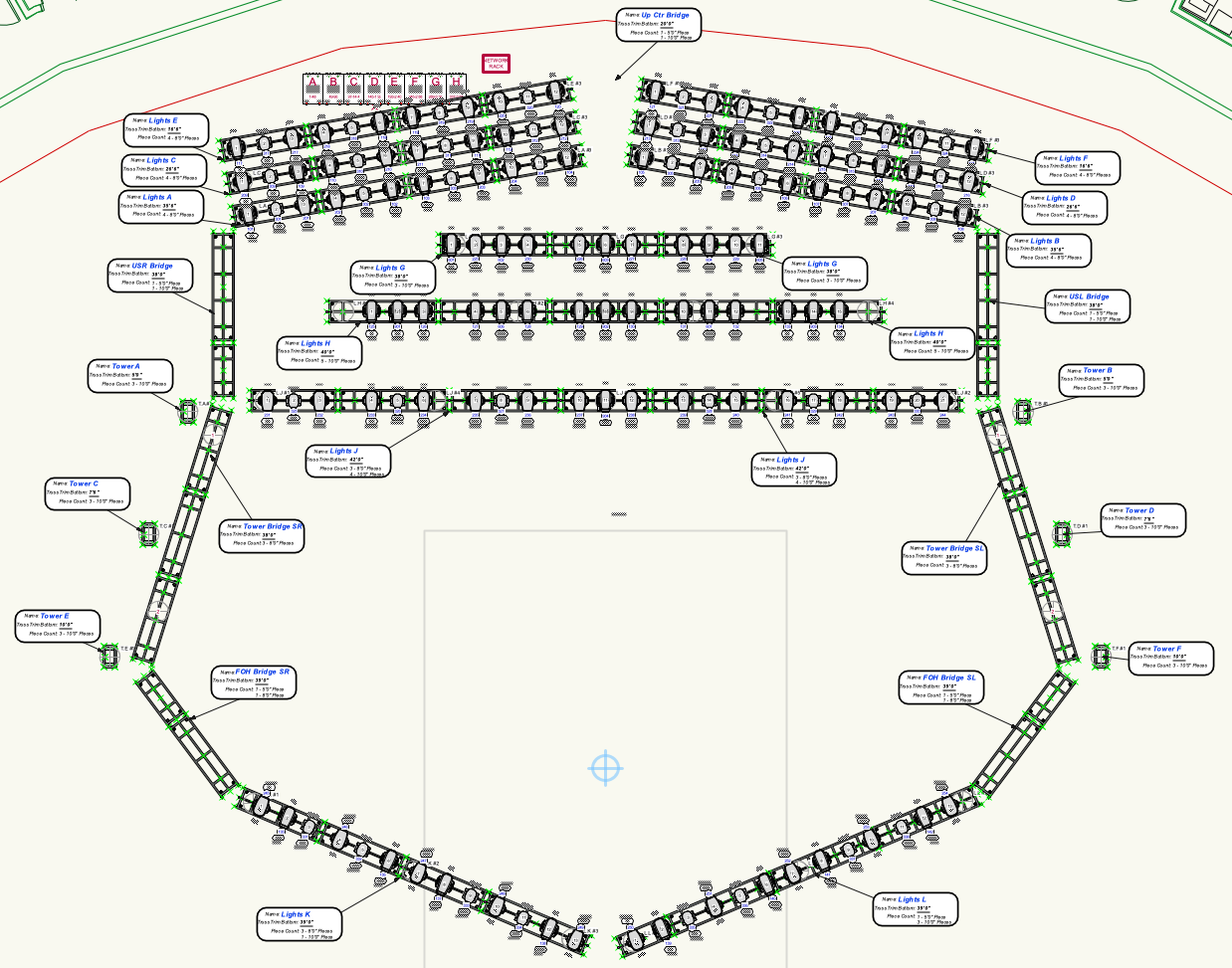
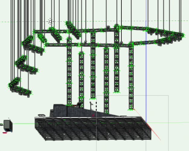
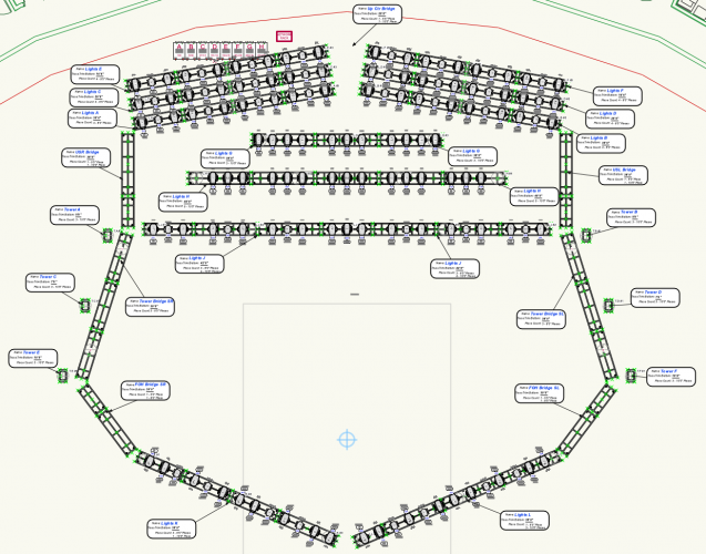
1. The only way the new cable tools can provide the necessary organizational information to create build lists of looms is for the user to make sure that no cable run object has more than one part. If there is such a cable run exists it must be broken into different objects using the split tool. If you are going to try and hav a workflow that can handle all the variety of cable run paths, then the above statement is absolute; there is no other way to do this. "A", not all the parts of a cable run will be members of the same loom, and "B" different parts of different cable runs will be in the same loom. 2. If you are going to control where all the parts of a given cable run land, you must do it with the split tool. This is an absolute rule. It is possible to draw the entire cable run as a single object, but you want to create loom build lists and/or more accurately control where the cable breaks land. The cable run must be split using the split tool into single part cable runs that are identified as a single cable run by the Cable ID. This still makes it difficult to create the stickers described above. It might be possible with a script. The "absoluteness" of these 2 rules is reinforced by the fact that only the whole cable run has a Loom ID. Each part needs a Loom ID, but cable parts are only virtual objects, data entries in a cable run object. The data structure of a cable run could be changed to accommodate loom IDs for each part, but that hasn't happened yet, and would not matter without better control of part end placement. I used and highlighted the word "absolute" because I wanted to be sure everyone takes notice. If you do not believe it, cable the rig below so that each separate truss stick (several connected truss objects), can be flown in without having to fly any thing else.
-
PS: Imagine the issues when different parts of a cable run are members of different looms. Try and generate the paperwork for that. Again, use the split tool to split every cable run into single cable run parts. I'm still looking for the "Loom" parameter field. Fun, fun.
-
Also, if you want to end a cable part at a geographic location that is a shorter distance than the part length, you will have to use the Split tool to cut the cable run into 2 parts that share a cable ID. Now the cable report has more than 1 row, and each row may have more than one part. That means that a report of parts cannot really coherently be done. So far, in my limited experience, the only way to get any kind of part location control and part reporting is to make sure that you split any cable run into individual cable parts using the split tool, making sure that no part has no more than 1 part inside it. You would then get a database report with each part of each cable run on a separate row related to each other by Cable ID. You would have to sort by Cable ID to make any sense of this, but you probably would anyway. So far, making build lists and cable stickers is a mess, unless Jesse can enlighten us further.
-
As best I understand it, you can't display the parts this way as part of a set of cable database rows. It might be possible to write a script to write the separate parts into separate regular worksheet cells.
-
?? What matrix?
-
Is it possible for VS to get the structural units of a .vwx file?
Sam Jones replied to Sam Jones's topic in Vectorscript
Not in my local 2021 version, but I'll go back and download and see if I get something newer. -
Is it possible for VS to get the structural units of a .vwx file?
Sam Jones replied to Sam Jones's topic in Vectorscript
The URL is what I needed. Even after emptying the cache, I can't get Safari to go to that version of the online Function Reference without clicking on the URL shown above.