All Activity
- Past hour
-
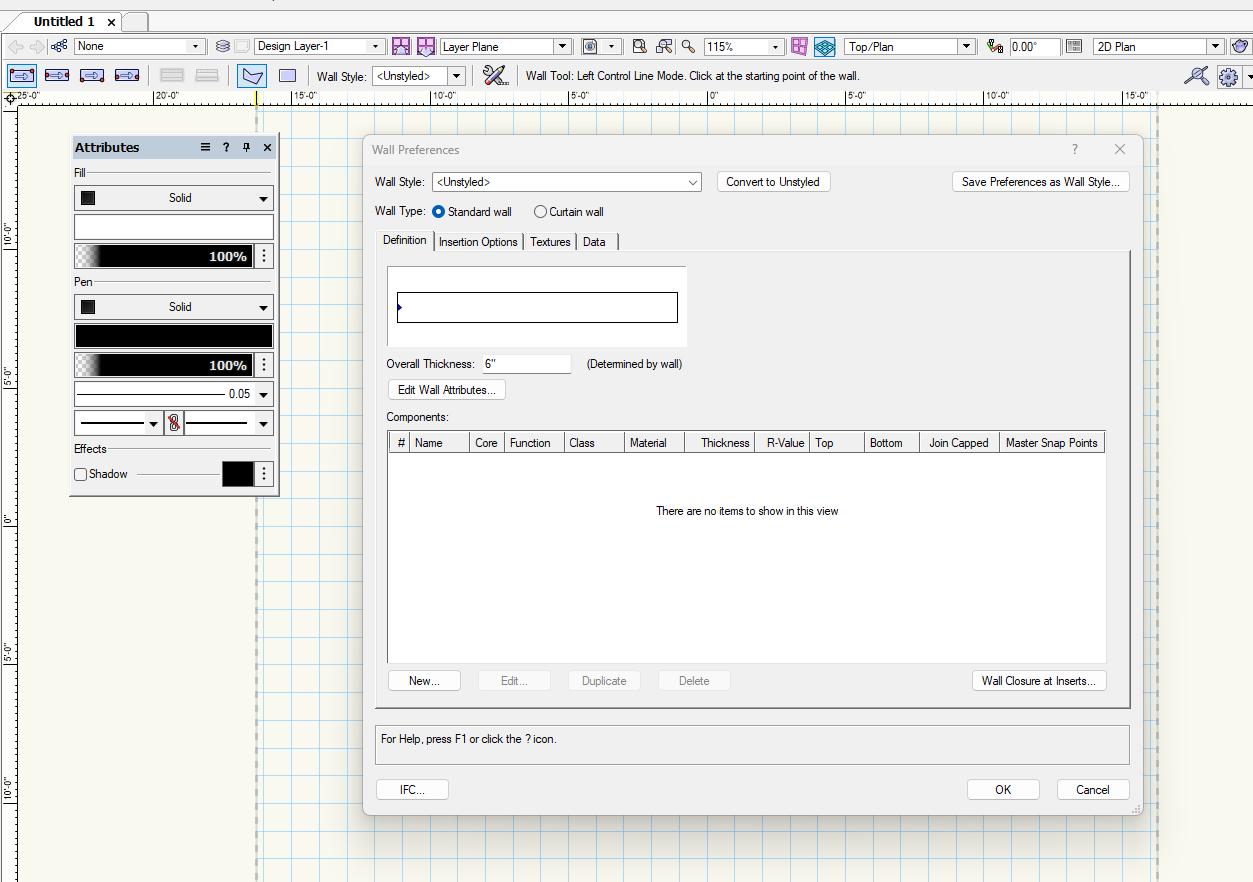
Once a drawing has a styled wall you can no longer make an unstyled / generic wall. Your best bet it to copy paste a wall from a blank document and then make your generic wall a wall style.
-
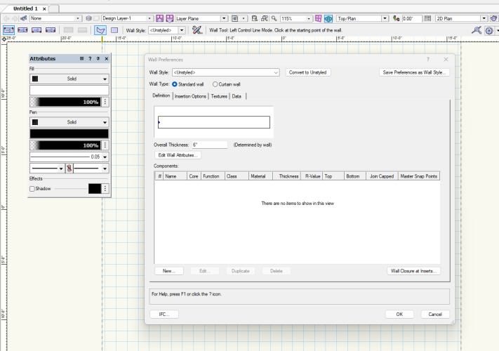
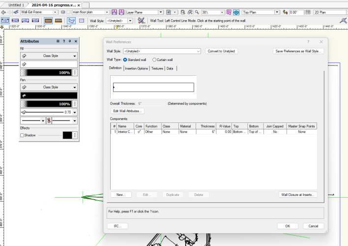
I use simple 'generic' walls quite a bit during preliminary design (no components, unbound), but have been having some problems recently. I must have changed a setting somewhere along the line. When using a work-in-progress file, I can no longer use generic walls. Clicking on the wall tool, under 'wall style' I select 'unstyled', and then normally I would be able to select whatever 'overall thickness' dimension I need, but it is now greyed out. So the only option is to select one of the generic walls from the Vectorworks library, which are often not quite right for my requirements. If I open a new file, the generic wall tool works just fine: What am I missing here? I have checked class and layer visibilities, and everything is set up correctly. And I am not using stories, so walls are drawn on a layer. Any suggestions would be appreciated.
-

'Proposed Contours' not working as expected in Site Model
nicovlogg replied to nicovlogg's question in Troubleshooting
Never mind, it's not letting me upload the file.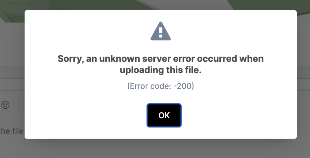
-
Makes complete sense + it's something I find annoying too. I think I've raised it previously but perhaps not as a Wishlist item... When you replace one styled wall for another (or edit an existing style) you get the option of determining whether the replacement wall will align centrally, to the left side or to the right side of the existing wall. It would be great to have the same option when you edit the width of an unstyled wall rather than the alignment be central by default. You're not doing anything wrong. All you can do is edit the thickness in the Wall Preferences (wrench + pencil icon) before drawing the Wall. Actually... it would be great for those of us who spend a lot of time modelling existing (old) buildings to be able to interactively resize an unstyled Wall's thickness like you can (now) with Doors + Windows...!
-
'Proposed Contours' not working as expected in Site Model
nicovlogg replied to nicovlogg's question in Troubleshooting
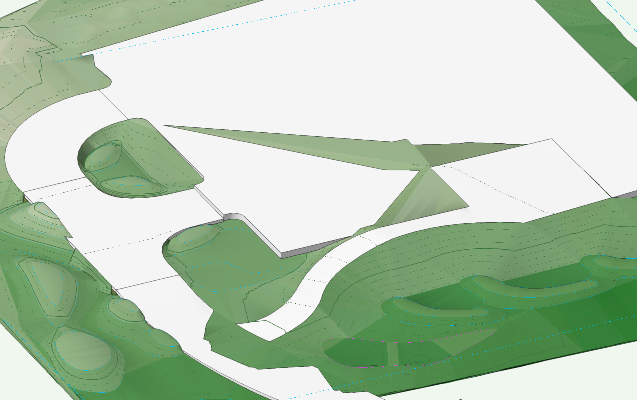
Hi Jeff Thanks for your time and the detailed breakdown. What I often miss is that Vectorworks has very specific rules about which 3D data differing line types have. I come from a Rhino background where a line is a line and all lines and points have 3D information. More adaptation is required than I expected. I have been working on the file a bit more, and now have some hardscapes and so on that I want to add. I am using a combination of arcs and lines and NURBS to get the curvy surfaces I'm looking for and they seem to be working OK. However for some reason the hardscapes are in some areas covered by the landscape, regardless of whether I use the 'cut landscape' option or not - what am I doing wrong here? Does this have something to do with the grade limit again? Can I simply extend the grade limit beyond the extents of the model so that it covers everything inside the site model? I will attach the file again. Thank you again.
- Today
-
 Dano Parke joined the community
 -
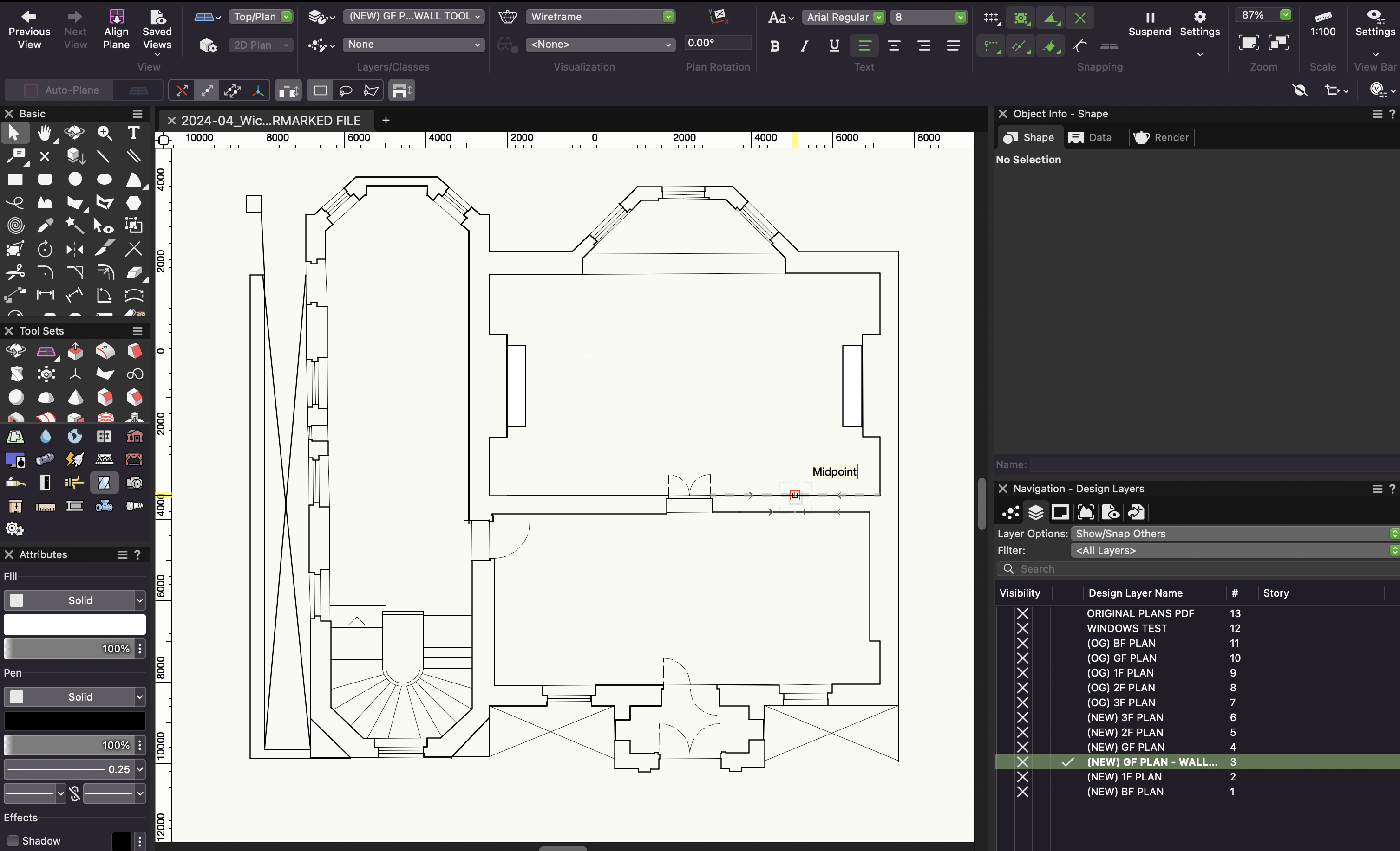
Thanks Tom. I'm struggling with using the wall tool because I go around the perimeter. Then I select each 'segment' and input the thickness, but then that thickness goes beyond perimeter line, i.e. from the central line the wall gets thicker 50% either side, rather than just 100% on the inner boundary line. Not sure if that makes sense. What am I doing wrong? Agreed, not the easiest project but hopefully if I get one floor sorted I'll be able to duplicate most of the work. Thanks
-
For some reason it only does this with my custom scripts, but why and what's the solution? Is it a bug? Dave
-
Worksheet function get alphabetic letter from number searched
Pat Stanford replied to matteoluigi's topic in Vectorscript
Look at C_HR and https://www.asciitable.com Capital A is C_HR(65), lower case a is C_HR(97) So C_HR(64+YourVariable) will give you the character in capital letters, C_HR(96+YourVariable) will give you the lower case. The forum does not allow the use of the real function name. So take the underscore out and it should work. -
 Here are some examples I threw together for you. rounding examples.vwx
 -
This is all doable with Wall/Doors/Windows. The internally curved walls shown in the file (but not in your screenshot) could be achieved with Wall Recesses: Not the easiest project to be embarking on so depends how much hair you're willing to pull out + overtime you're willing to put in to get there... What is it about Walls with different widths that you're finding a nightmare?


-
Don't change the formula. You can't combine Data Tag functions + Worksheet functions.
-
 @Jesse Cogswell Thanks for looking into this - It seems like it's more trouble than it's worth. Cheers! Nic
 -
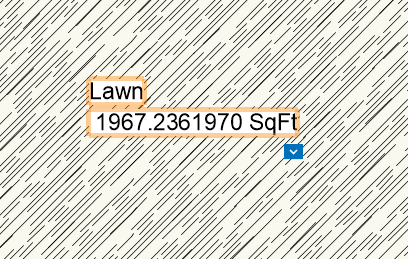
Thanks Tom I changed the formula to: #Landscape Area#.#area##WS_(INT(AREA/10)*10)+10# SqFt I got this result: Unfortunately, no rounding at all.
-
In a Data Tag try #WS_(INT(AREA/10)*10)+10# SqFt to round up to nearest 10 or #WS_(INT(AREA/100)*100)+100# SqFt to round up to nearest 100.
-
 Hi, sry for my post here but there doesn’t exist a forum for worksheet scripting. I am looking for a function that could get me an alphabetic letter from a number. 1=A … 26=Z or do I have to solve it with an IFS-clause? (btw I think that worksheets, data manager, data stamp,… should all base on vectorscript and/or maybe python) thanks matteo
 -
Well Don't I feel like an idiot. Life lesson, dont ask till you've scrolled all the way down. 😅 Thanks Andrew
-
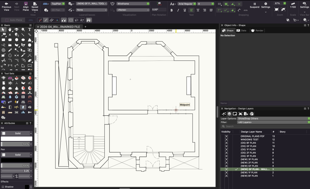
Hi there, I am needing some help with a project I am working on. I am struggling to know how to 3D model the attached building. This floor plan shown originates from an architects' plans which I have re-traced. Because of the 'trickiness' and complexity of the building (lots of indentations etc) I thought to initially extrude polygons in order to create walls etc, but given the number of windows in the house / potential future level changes I thought it might be better to use the wall tool and then insert Georgian sash windows. What would be the approach you would take? I have tried to use the wall tool but when it comes to setting different wall widths for each section I am having a nightmare. Any advice would be more than appreciated. Attaching model if anybody needs to see it / show anything in particular. Thanks! 2024-04_Wick House_MODEL.vwx
-
Look for the "Tilt" parameter in the OIP.
-
Edit the door settings to change whether it's opening direction is pre-set or not.
-
A bit off topic - I was sent here by @Jeff Prince I'm trying to round a landscape area data tag and he mentioned you had listed the proper syntax here... I'm not quite getting where the rounding formula is stated anywhere above. The suggested formula by the 'define tag field' menu is: #Landscape Area#.#area##prec_0# After looking at all your posts I tried #prec_0_2# but that just adds a "_2" to the end. I tried throwing "round" into the equation in various places, but no success. Any thoughts? An official guild would be so helpful - as it is now, those of us that are trying to learn syntax are at the mercy of the old guard - usually @Pat Stanford - taking the time to help out. Pat is great, and very responsive, but he can't be the only source - the man has to sleep sometimes!
-
So, I have an upcoming event that the LED supplier has designed a truss frame around an LED wall and the truss and screens will be flown at an angle of 24° over a stage. Is there a way to force the LED screen tool to tilt the panels forward to align with the truss? The rotate tools wont allow it.
-
 Jeff - thanks form the lead, but I'm not finding anything in that post with rounding formulas... I tried adding #area##in_2_0# instead of the #area##prec_0#, but this did not round. I also tried using #Prec_2_0# which did not work either. Any chance you could give me the syntax for a rounding formula for #landscape area#? ...or a link to the help pages where they list rounding formulas?
 -
They are working for me, both using the 'Flip' button + the 'Hinge Side' + 'Swing Direction' settings. Perhaps post a video or a file.
-
Hmmh, but that would .... flip the Wall ..... which in case of a Curtain Wall isn't often wanted. E.g. that would move the glass panels to the inside of the Wall and such things.
-
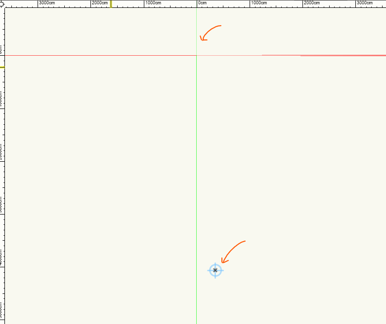
 Hi to everybody, I have a question about user/internal origin. I read in the manual: Why when a create an empty drawing, using no template, my user and internal drawing are not coincident? (screenshot below is taken on an empty new drawing) They are also on different Z. Also, it seems to me that is possible to move the origin on x,y and not in the z. Am I missing something? Would anybody explain me this concept? Thank you very much, Davide