Jake Wilson
-
Posts
15 -
Joined
-
Last visited
-
Hey all Not sure if there is a thread that covers my questions, if so please direct me there. I work in events and often have to create room templates for venues we regularly visit, hotel ballrooms, convention centers etc... I have been trying to create custom designed stairways to match event spaces for quite some time now with little luck. I normally have to just fudge it or build stairways one step at a time which is very time consuming. I have tried using the reshape tool but its constraints are far too limiting. Any ideas how I can create a 3D representation of stairs like this?
-
Hi, I tried to open the file you shared in VW2024 design suite and all I see is an empty design layer. I checked the classes and everything is visible Layer options are Show/Snap others The OIP data tab shows some light information(plug type and temp) I downloaded and opened like any other file and got the this file was created in an older blah blah blah Not sure what I'm missing here
-
I have noticed recently that some symbols and objects, usually World based, don't share the same Z axis zero point. In the attached file I have a stick of 12" Prolyte truss from the VW library that is good and an Applied 16" truss symbol extracted from a DWG file where I have to 3d move the truss up 8" to react the same zero Z as the Prolyte. Can someone explain what's happening here and how I can change the symbol and any future symbols to avoid this? truss Z.vwx
-
I have never defined the working plane as far as I know. I've always used the rotate / rotate 3D functions in the modify menu. When I move between top/plan and front view VW generally shows me the front center of the symbol / object and I move up my view manually to where I need to be. On the odd occasion when I have need to rotate an entire drawing I will move everything onto one layer and group before rotating then move things back to their separate layers. I use Layers as locations for symbols in a drawing and Classes as parts of symbol in a drawing to avoid overlap that is difficult to see through and make things easier for me to manipulate in 3D
-
Not sure why there is not a reply option for each individual answer but here goes. LarryO: The symbol was created in AutoCAD by the manufacturer and sent as a DWG file, I imported it and when directly to the front view by pressing the 2 button on my keyboard, to review the symbol and it was laying on it's side, the symbol is a truss tower for a truss roof crawler system so it is not difficult to know it's proper orientation. As it is comprised of multiple pieces I then selected them all, grouped them and then, still in the Front view used Modify/rotate/rotate left 90° and the tower stood up with half of its height below the 0-Z point, I then 3D moved it up so the bottom of the tower would sit at the 0 point. Now when I ungroup and try to use the 3D move and enter a distance i the Z axis the piece of the tower I am trying to move up moves to the right as thogh the z axis moved with the tower when I rotated the tower. michaelk: Please expand on your working plane theory, I assumed I was always on the working plane and just changing my view points from top plan to front, back, side etc...
-
Ok, so I requested a symbol from a manufacturer for one of their products and their designers sent me the multi part symbol DWG file(Hybrid I guess) and the symbol was laying on its side in the drawing. I double clicked it and selected everything, grouped it and rotated it 90° to a standing position and adjusted its height to the Zero point (drives me crazy that we have to re-zero things when they are rotated, when you rotate the bottom zero point should automatically change to the new bottom point. Rant over) Anyway, I am now trying to alter the symbol to add physical height to it, I select the top section and try to 3D move it up 10' to accommodate a new section below (yes it has to be done this way.) when I open Move 3D and use the Z axis to raise the top instead of moving up it moves to the side as though the symbol was still on its side. I'm sure the solution is something simple, how do I change the symbol so Vectorworks sees it as standing instead of laying on its side?
-
Hey Alex Can you expand on this a bit. I followed your directions and ended up with the attached file. I modeled the screen with one of the screens I use at work and just manually rotated each column then composed and add solids. Am I missing some thing? Thanks curve screen test.vwx
-
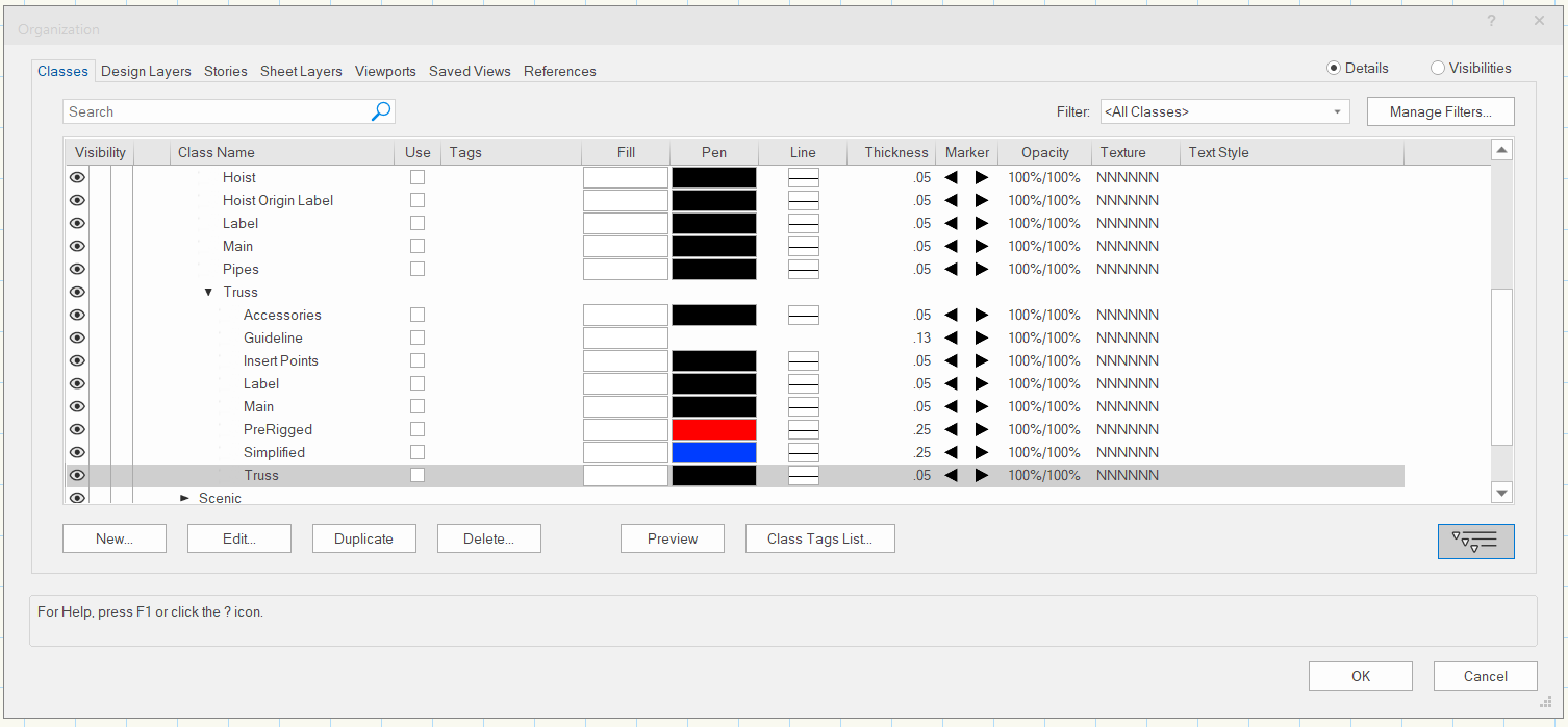
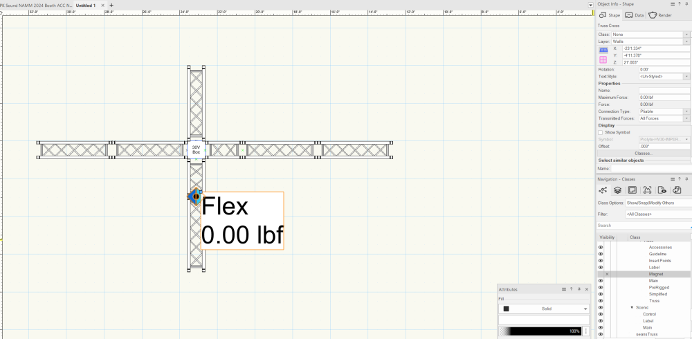
Attached is what the class list looks like in my generic spotlight template I use for creating drawings. I don't see truss cross and when I search in classes for truss cross I get "There are no items in this view" and yet when I put truss together the crosses pop up randomly. When they do pop up their class is always none. I have no idea why the cross chose the section in the attached picture and not all the others, the truss is all exactly the same Prolyte just different lengths, they are all classed rigging-truss-truss as is the corner block. I CTRL/Shift and drag a piece away and then drag it to its new connection or simply mirror tool it and at random times the cross will pop up. I have tried shutting off the magnet class in rigging-truss which seems to stop them popping up while im working on that session but once I save and reopen they start popping up again. many times I have re-classed them to a new class and turned off the class only to find they reappear when I open the file the next day as duplicates of none class, when I check the new class I created to turn them off, the ones I turned off are there so the duplicates are new. I have been a VW user for more than a decade and this function of braceworks is by far the most useless and annoying. I purchased Vectorworks and I am really tired of a program I did not order or ever want (braceworks) messing with my drawings and slowing my work down.

-
This crap is still happening, it's been almost 2 years now. This is not a truss corner problem and not a tomcat problem as this happens with all truss brands and sizes. This is a Braceworks problem. Braceworks is garbage, I did not purchase Braceworks, I purchased Vectorworks. I do not want Braceworks. I don't need Braceworks help with load calculations, or telling me that two pieces of truss are connected, I know they're connected, I connected them. Having to constantly stop and reclass these stupid pointless crosses is seriously affecting my workflow. Please give those of us who do not want Braceworks the option turn them off completely. We are paying money every year for the software to work not tell us how we should work. Fix this.
-

Arena Model Available
Jake Wilson replied to scottmoore's topic in 3rd Party Services, Products and Events
Fantastic job, great time saver thank you. I will be recommending this to everyone I know that works in VW. If I can make one request it would be an update for the seating sections to make the aisle count from ice level to concourse level adjustable in two or four row ring sections and to raise and lower the concourse entrances to suite small and medium arenas. -
Jake Wilson changed their profile photo
-
No such luck, the entire wall is a window that is leaning out away from the room about 10° as well as being angled at 7°. I get an error saying the only hybrid objects can be rotated.
-
Hello all, PC user with Design Suite 23, 72GB Ram (system and Graphics card). I am working on a room that has an entire 55' tall x 188' wide window wall that leans out away from the center of the room by about 5° at the top. How can I lean this wall? The drawing will be used for event design. The 2D view of this wall is not important and will have zero effect on event design. Only 3D matters. Any help is appreciated.
-
resizable frame over walkthrough tool
Jake Wilson replied to Jake Wilson's question in Troubleshooting
That did it Thank you Andy. Been driving me nuts. -
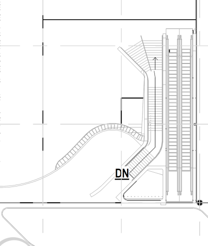
I'm working in design suite 23 trying to build a room that has structural Wilson style arched truss. Does anyone know a way to create this type of truss? See attached image for example of truss type I'm looking for. Thanks

-
Jake Wilson joined the community
-
Hey all, I need some help, I have a drawing that someone else gave me that seems to have an odd setting I have not seen before. I'm running 2023 design suite and the drawing in questions was created in an older version. When I take the drawing in to walkthrough mode there is an odd frame that is resizable but limits the zoom and flyover functions, when i try to flyover the drawing seems to stretch out of shape but if I go back to top/plan view and then use flyover everything is fine. Also when in Walkthrough if I use the pan tool all it moves is the framed work space so I can't re-center my drawing in walkthrough.