Search the Community
Showing results for tags 'landmark'.
-
We have a new issue, never encountered prior to VW2018. Currently we are having difficulty with Plant plug-in object visibilities...I've attached 2 screenshot videos (no narration, sorry) that show what we are encountering, but I will do my best to explain. We have (8) different classes...
-
Hi there, I've had this issue come up a few times over my last few projects. I've previously managed to find work arounds but never solutions. Can anyone tell me why my hardscape objects render as black polygons rather than the textures I've assigned them? I have tried differ...


-
I'm trying to add multiple plant species into a hedgerow object and I can't seem to add more than 7 species - is this a restriction of using a hedgerow does anyone know? If I was to use a landscape area I could have loads more species.
-
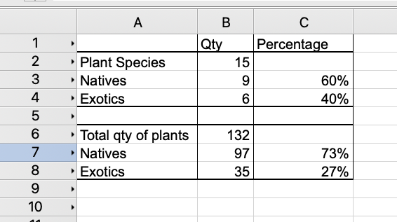
Hi all, I need to create a worksheet for local government compliance. In the past I have been doing this manually and I'm over it. In the worksheet I need to show the total number of plants and of that how many are natives and how many are exotics with percentages in the next colu...
-
 I would like the ability to choose "insertion point" or "center" for auto placement. As it is a data tag seems to attach to the center of the object (when using the "all eligible object mode" at least). It would be nice to have a setting to snap to center of object OR snap to...
-
Hi I have been having issues with worksheets on sheet layers. I have tried playing the worksheet on a sheet layer duplicating it as it won't fit on one landscape page. The other option I have tried is placing the worksheet on the design layer and use 2 viewports. The second viewport doesnt appear wh...
-
We are in need of a draftsman or designer for Remote, Contract work. We are a full-service Landscape Architecture firm. We need someone that can prepare Landscape Plans in Landmark. This is a remote position but would prefer experience in the southeast United States. Experience in the en...
-
 Looking to establish a cooperative arrangement with a competent VW Landmark practitioner for drafting work. Small practice with both residential and commercial landscape design work. 2D plans required range from base plans, to concept plans, to construction plans, elevation plans, sections and detai...
 -
Is there a way to turn off the automatic irrigation network update that occurs at every pipe connection? The disruption to workflow with having to wait 5-10 seconds after every single lateral pipe placement is getting to be quite tedious on larger irrigation plans. I cannot find any setting to disa...
-
 It it possible to createa road on a site model with a complex cross section profile? I have to design a road with a compelx road - gutter - shoulder profile. Look image attached . The examples in VW Land design only offers a road with a simpel square gutter. Any help?
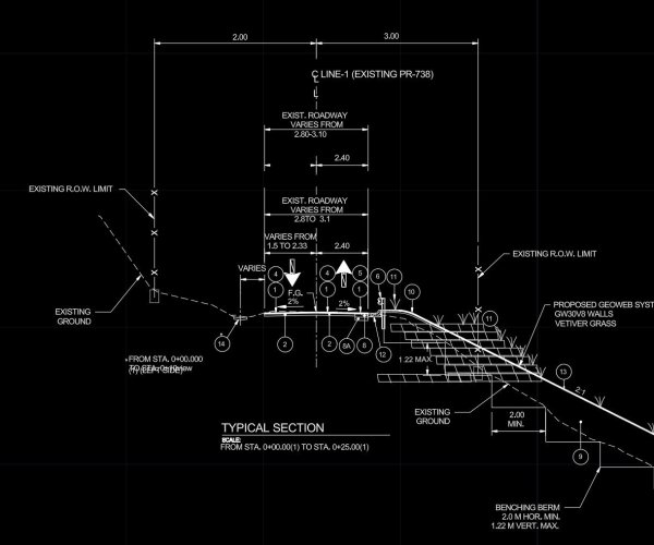
-
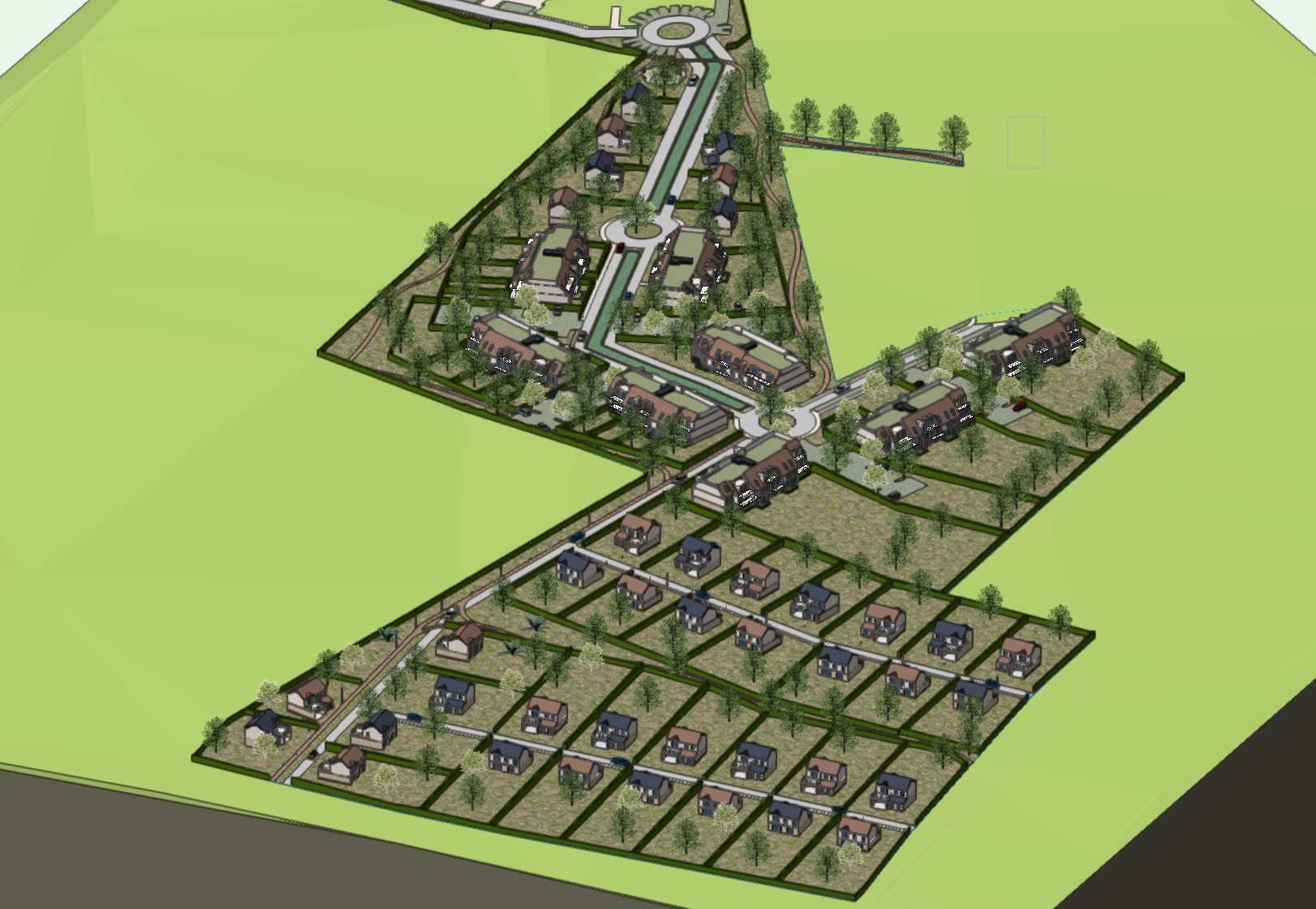
Hello, How do you guys manage your workflow withou making your Vectorworks files bulky. In the exemple below i have use reference for my buildings and house. My files have reach 600MB and i am yet to create viewport for presentation and print. The file contains vehi...

-
I would like to request Unit and Labelling for the grade tool similar to the Stake Tool. Units for grading are often not the same as the drawing units. our drawings are usually millimetres and vertical grading units are often metres to conform to the survey units. Also the ability to la...
-
I've been trying to find the solution to this for a while, but I'm not sure if I'm googling the correct terms. I want to make the Borders of Hardscapes more real-world accurate. When I apply a texture to the Border Slab in the Object Info, it visually looks like the rest of the hardscape...
-

Assign class to a plant
James Dawson Design posted a question in Wishlist - Feature and Content Requests
Hi, I would love to be able to place a plant and it automatically assigns to a class, regardless of the current class setting. -
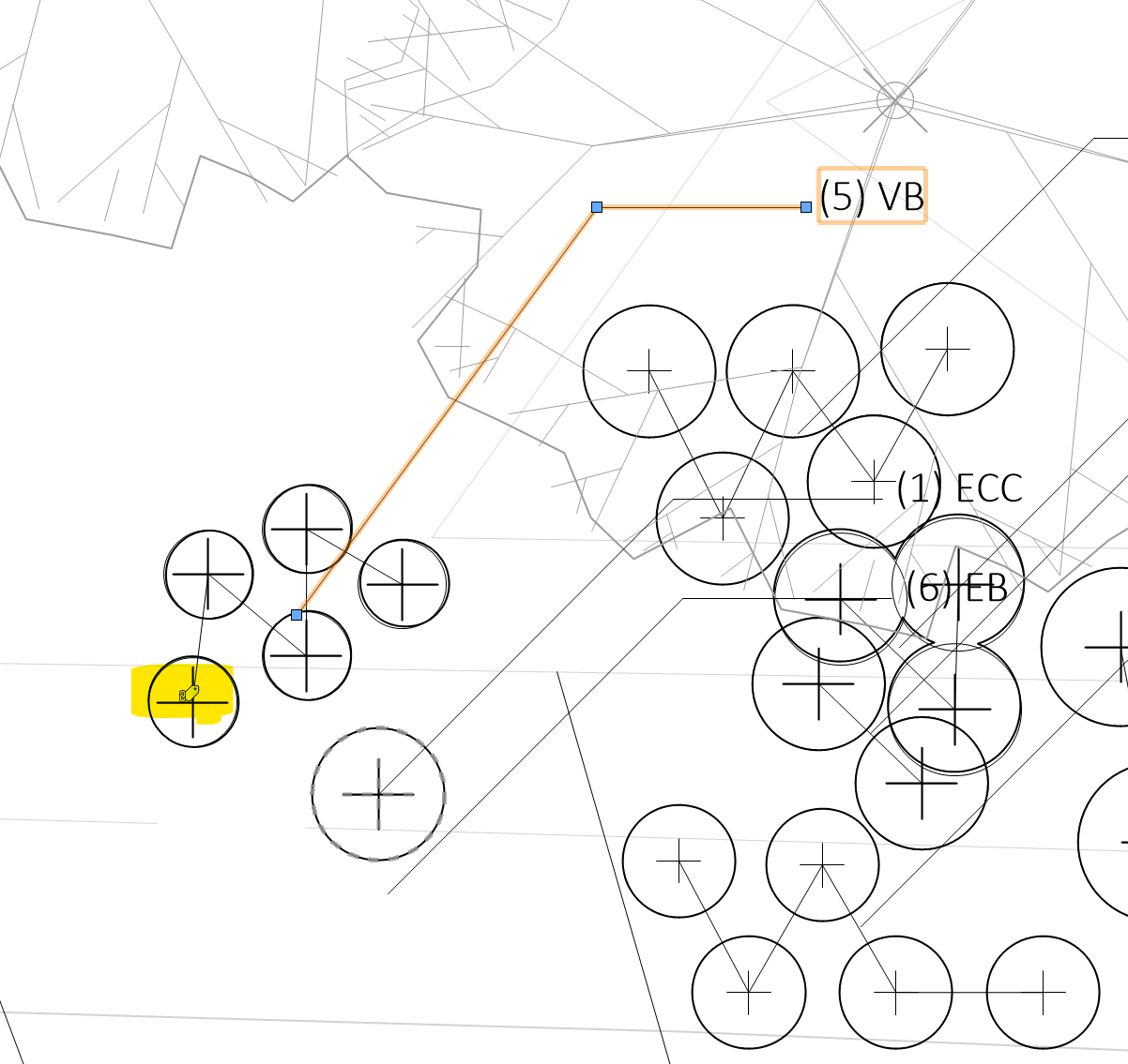
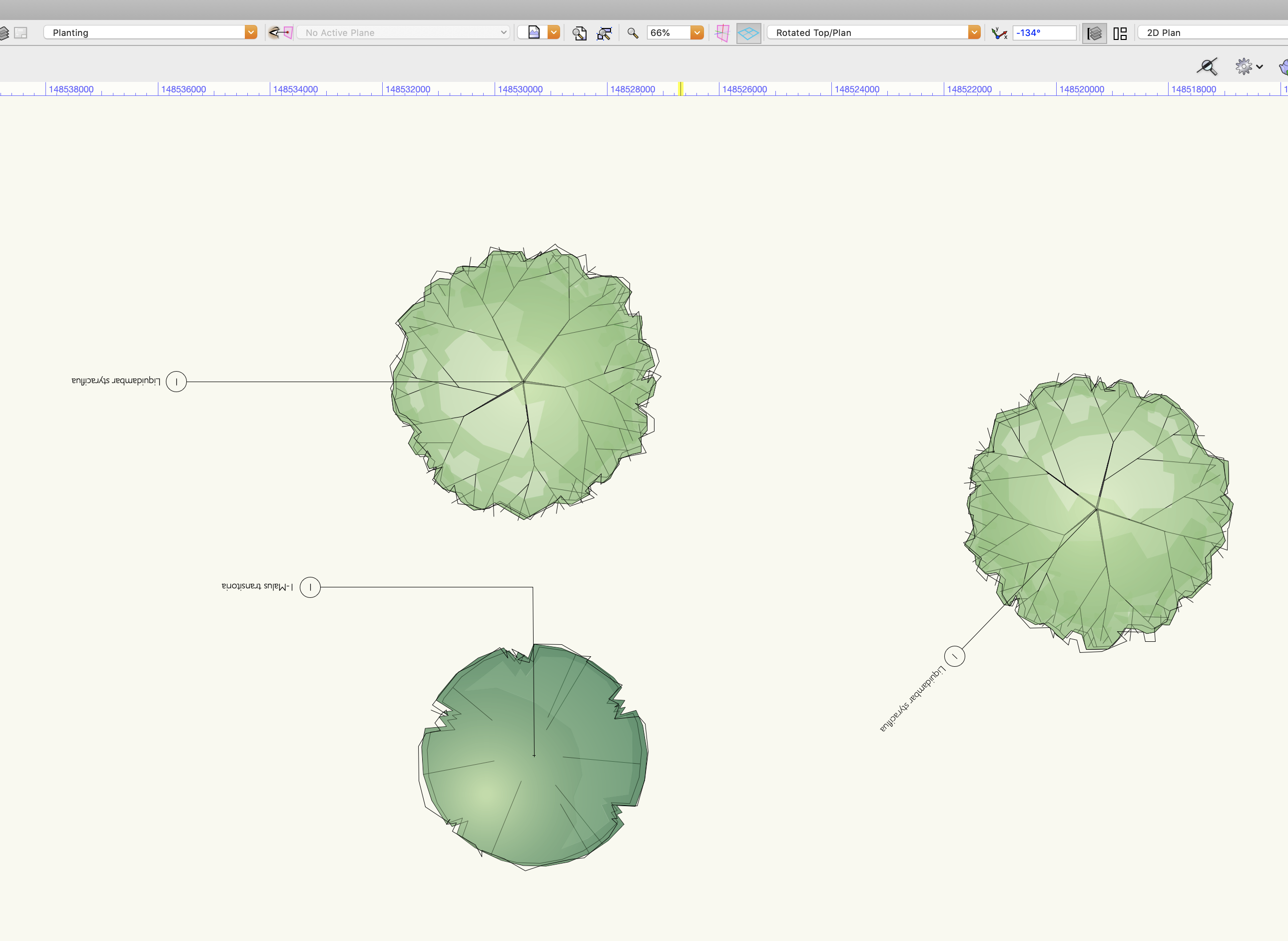
Help please, I am finding it impossible to insert plants onto a rotated plan and get the tags to behave. Desperate to know how to resolve this asap. This plan is rotated -134. The tag text is upside down, whichever way i rotate it. I have tried inserting plants t...

-
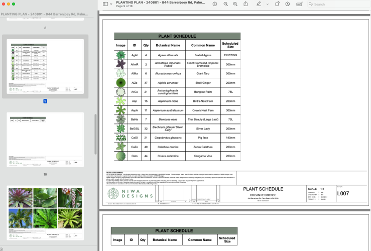
I am working in VW 2023 and there is one plant symbol that won't show up in the schedule. It is on the correct class and layer (same as all other plants) and I have tried duplicating it as advised by someone in another post having the same problem. Any idea why this is the case?
-
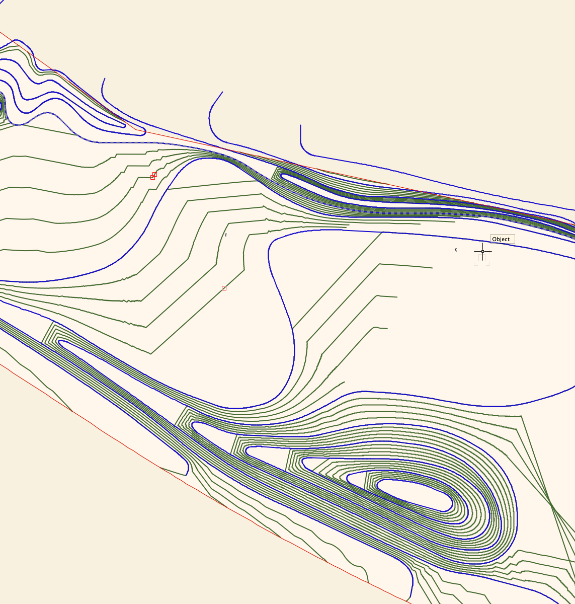
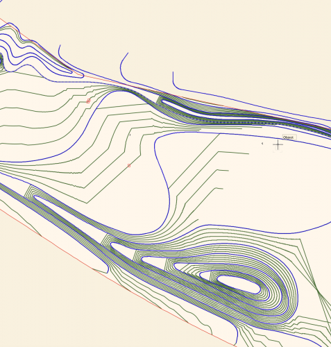
I'm wondering if I'm missing something in terms of the control we have over site modelling in Vectorworks. I've attached a screengrab of a site model I have created. Blue lines are the 3D polyline contours I have drawn and set to 0.5m height intervals, the green lines are the contour lin...
-
I have a site model if a area alone the water front. I am set contour data for areas on the water to be below 0 (negative levels) I will like this surfaces site model to render blue color to allow clearly differentiate between upland and wetland. Here is a link to the VW file...
-
 We're seeking an experienced Vectorworks ‘Landmark’ designer/drafter starting on an as-needed/contract basis to build to a long term position. This position is preferably filled by someone in Ontario OR has working knowledge of regional and Municipal building, planting and permitting requirements....
 -

Gradient Cut Fill Site Model Visualization
ericjhberg posted a question in Wishlist - Feature and Content Requests
It would be awesome if you could generate a 2-dimensional visualization of a Site Model's cut/fill, but instead of just static Cut = Red and Fill = Blue...you could assign a gradient for each that could color the site model based on cut severity or fill severity. For example a White to Red gradient...- 4 replies
-
- 4
-

-
- site model
- landmark
- (and 2 more)
-
I am trying to streamline the documentation process for designed plant communities for both installation and visualizing with clients (along with my own forgetfulness). I have a resource drawing that I keep for plant objects with records attached that describes the varying interest seaso...
-
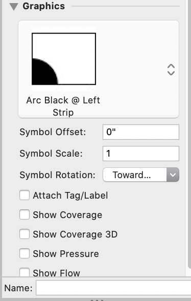
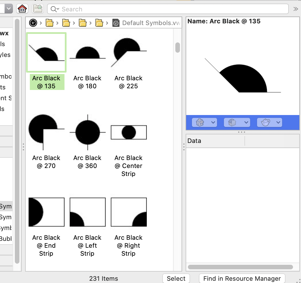
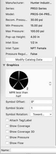
Anyone know how to apply the correct symbol for irrigation heads (get it to "stick")? When I pick the correct symbol (1/3 head, standard vectorworks symbol, filled), vectorworks picks a different, wrong symbol (Q head, unfilled). Luckily, the catalog data remains the same. Replacing...


-
Hello, Im using Vectorworks 2021 SP1 and I just tried to use the VBvisual Plant Tool - More Plants but it gives me an error page and I can't download more plants. Do you know any website where I can download new plants to complete my design? I'll prefer not to use the Plant tool because th...
-
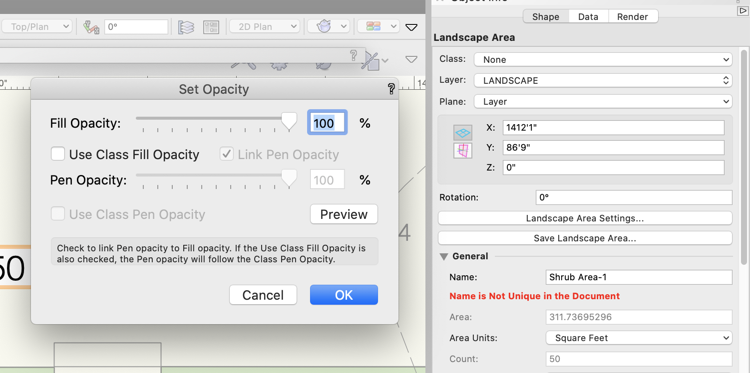
 For years, I've been wishing that you could assign different opacities to fill and pen style in a Landscape Area. You can do this with most other objects, but not a landscape area. It would make life a lot simpler as I like drafting with a more transparent fill, while having the pen set to 100%....
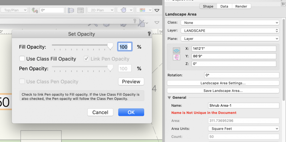
- 3 replies
-
- 7
-
-
- site design
- landmark
- (and 3 more)
-
Shut up and take my money!!!
jpccrodrigues posted a question in Wishlist - Feature and Content Requests
https://paper.dropbox.com/doc/Land-Kit-BETA-R9DujKA3zEYp69LBbOjbq Talking about logarithmic design, this is the direction that VW should look at!!! Really makes me consider start learning a new software https://tse2.mm.bing.net/th?id=OGC.ec3def206059f4eae13c2385248ab72b...