EmmaLa
-
Posts
10 -
Joined
-
Last visited
Recent Profile Visitors
146 profile views


-
How to create a curved bench seat with vertical batten array back rest
EmmaLa replied to EmmaLa's topic in General Discussion
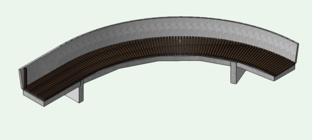
Thanks all. After trying a few differrent things I found the best way to array battens along curved face of backrest was to duplicate batten along nurbs curve with fixed distance mode. This resulted in the batten profile staying the same along the curve, but the gap between battens changes between the inner and outer arc.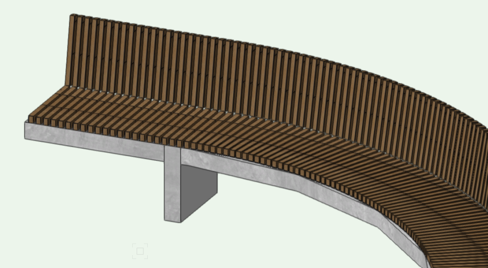
-
How to create a curved bench seat with vertical batten array back rest
EmmaLa replied to EmmaLa's topic in General Discussion
Thanks @Peter Neufeld. This seems like a good method for creating curves - however after following your steps I just got a message 'deform tool failed'. This is a frustrating brick wall I seem to run into a lot with vectorworks modelling. It would be so good if it told me why it failed! Also noting with this method - is there a way to then 'explode' solids after add solids and deform has happened, so that the battens are separate to the concrete base and correct textures can be applied? -
How to create a curved bench seat with vertical batten array back rest
EmmaLa replied to EmmaLa's topic in General Discussion
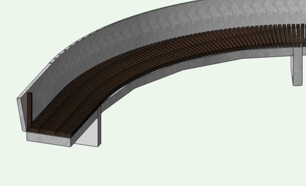
Thanks for your help everyone. @Tom W. unfortunately this didn't work for me. The backrest is for some reason in segments and so the extract tool doesn't produce a single nurbs curve along the top edge. See image below for reference: Is there a straightforward way of creating this backrest with the angle 10degrees that I am missing?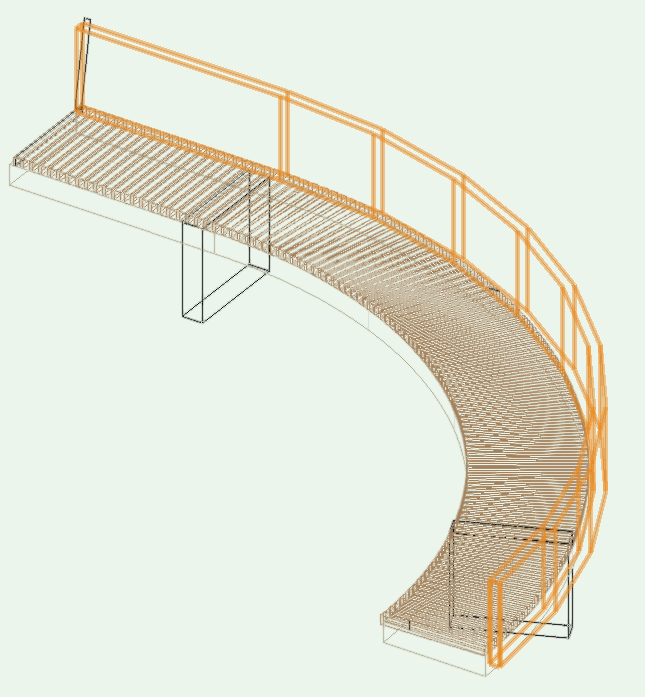
-
I am new to Vectorworks 3D modelling capabilities and am trying to model a curved bench seat that features vertical timber battens as a backrest at an angle of 10degrees. I've managed to create the seat components (a base with battens arrayed along curve) and a solid backrest at the angle I want, but I can't figure out how to array the vertical battens for the backrest at the correct angle. Here are a couple of snips showing where I'm at:
-
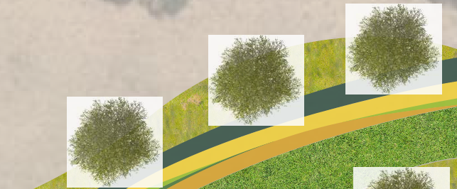
I am working with transparent Bitmap symbols in my drawing and having some issues when exporting the file to pdf. For reference, I am exporting several plans as pdfs in Vectorworks and the symbols appear as they do in my viewport (no issues with graphics transparency), however when I PDF the presentation that has the exported pdfs as links in Adobe InDesign, I am presented with the issue below (bitmap background graphics showing) I have tried exporting as jpegs, which solves the transparency issue in my final PDF. But the file sizes are just too large, and compressing them I lose a lot of quality. Any help would be much appreciated!
-
Thank you Jonathan. I have just solved the issue. I went through each symbol and there appeared to be a 'ghost' symbol among them that had no category - this didn't appear in the library/resource manager so it's a bit confusing where it came from. My workaround was selecting all and changing the category in OIP Thanks for your help
-
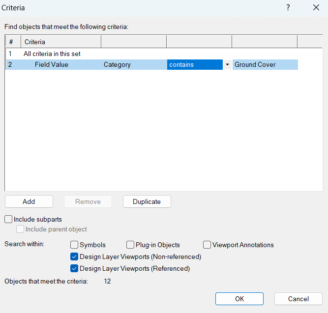
Thanks for your help, unfortunately no luck though. The criteria for the missing plant has the data that should pick it up...so I'm completely stumped
-
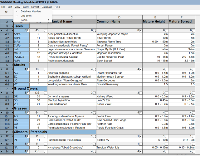
I am working in VW 2023 and there is one plant symbol that won't show up in the schedule. It is on the correct class and layer (same as all other plants) and I have tried duplicating it as advised by someone in another post having the same problem. Any idea why this is the case?
-
Hi there, I am having the same issue with a single plant not showing in schedule. I have tried all of the above but still no luck...any other ideas?!
-
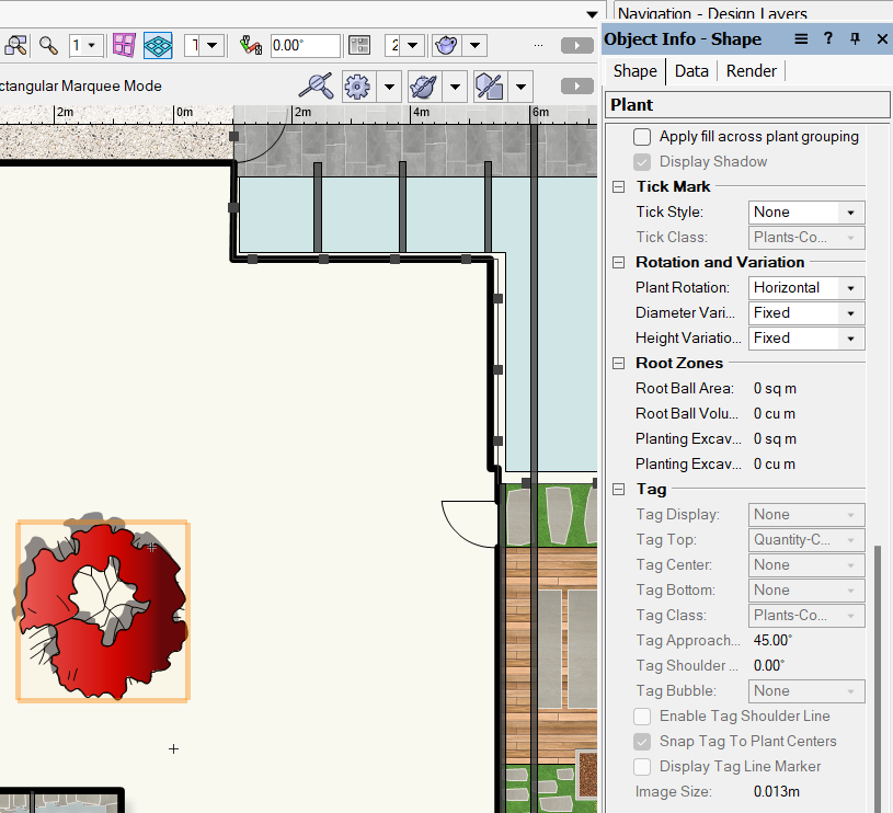
Plant data and tag information greyed out in Object Info
EmmaLa posted a question in Troubleshooting
I am working in Vectorworks landmark 2023 and have encountered a couple of problems I have not seen in previous versions. Using a plant symbol from the vectorworks library, the plant data and tag information are all greyed out in the object info palette - meaning there is no option to display plant tag data attributed to the symbol in my drawing. Another odd one - on the symbols where the data tag is showing, it is locked in the vertical plane...can' figure out how to move it!