CipesDesign
-
Posts
5,153 -
Joined
-
Last visited
Content Type
Profiles
Forums
Events
Articles
Marionette
Store
Everything posted by CipesDesign
-
RW Texture should follow length of Framing Members
CipesDesign replied to Christiaan's question in Wishlist - Feature and Content Requests
In the Edit Texture Dialog, next to the Color [Image eg] Pulldown, click the Edit button. Then click the Rotate button. Voila!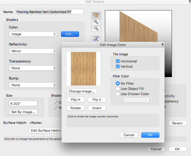
-
psm, Using the the Edit Workspace command, search for the Fit Walls command, and if it's available you can add it to your workspace. Boh, yes that is one way to skin this cat!
-
Not Subtract. Use the command Fit Walls To Objects . Subtracting will turn the walls into generic 3d forms, losing all parametric ability.
-
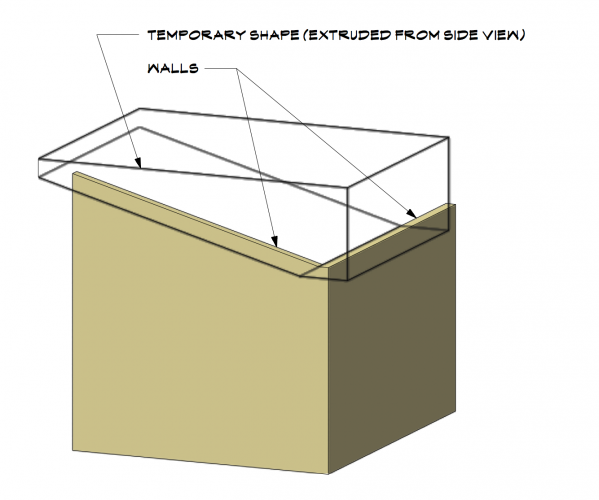
The easiest way to work around this (which occurs due to the mitered wall join at corners) is to create a Temporary Shape and us it as the "Fit To" object in the Fit Walls to Objects command. The shape must be Solid and must completely cover the portion of the wall you wish to reshape. P
-
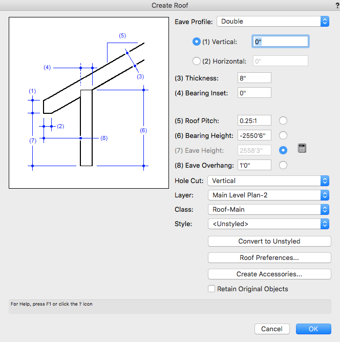
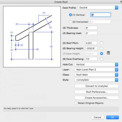
In the Create Roof dialog, you can enter a pitch (slope) value in the following format: .25:1 (eg). See attached
-
Many ways to do this. And no roof is actually totally flat. 1) try giving slope a small value (1/4" per foot, eg); 2) Use a Roof Face instead of a Roof; 3) If you really want it totally flat, try using a Floor Object; 4) You can use a simple extrude (but a Floor is better, with more control over textures and graphics).
-
https://forum.vectorworks.net/index.php?/topic/55005-tji-wood-i-beam-built-in-shapes/
-
TJI / Wood I-Beam Built IN Shapes
CipesDesign replied to Tom Klaber's question in Wishlist - Feature and Content Requests
Try using a "Framing Member" object, set to: Type= Wood Floor Truss; and at the very bottom of the the OIP, check "Use Solid Web". The rest should be self evident. -
Hi Stephanie, Sorry I didn't understand your original question! I am not super savvy with the Plant Placement tool. Hopefully someone who is can jump in?? One suggestion that may or may not help: Select the Plant, then in the Object Info Palette click on Plant Settings, you should be able to choose from the Plants in your current document (or others from default or other content).
-
A SYMBOL can only have one specific definition. There is no way to change only one symbol without changing all other instances of that symbol (with one exception, which is a "scaled symbol"; same exact definition; different size). In order to do what (I think) you want to do, go to the Resource Browser and Duplicate the Symbol (and name it as you like), then modify the new Symbol as you wish. Another method which *might* work for limited purposes (eg: only one or two are needed) is to select the instance of the Symbol to be modified and Convert to Group. You will then be able to enter and edit the Group (but you will lose any parametric abilities, and although you can make a duplicate of the Group, it will not be a Symbol)
-
Not exactly, but you can use the Move command to move each by the same exact distance. The Move command will retain the most recently entered numbers, so this is a pretty fast way to achieve what you're after. Another way is to select both walls and then drag them together; or better, select them both then Group, then drag, then Ungroup.
-
If the Site Model and the Walls are in different Design Layers (as they should be) check the Elevation (Z) of the Layer in which the Walls reside... For this (your) example, try setting the Z of both Layer to the same elevation; or if there is a compelling reason to leave the Layers at different elev's, do the math and adjust the Walls accordingly.
-
Move it up or down using the Move 3d command. When you create a Roof make sure to set the Bearing Height to the correct value. I usually set up my Design Layers so that the Floor Plan (where the Walls are) and the Roof layers have the same Z (elevation) value. Then when I create a Roof there is no additional math to do [eg: if walls are 8 ft high, then Roof will bear at 8 ft].
-
I (or someone) would need to see your file to trouble shoot it. If small enough you could post it here and hopefully someone will have time to take a look. FWIW, I have also had problems with Retaining Walls and the auto generated Site Modifiers (Pads and Boundaries). I generally prefer to use Pads, etc to do the "grading" first, then add regular walls as needed. It takes a little longer but seems to afford more control.
-
Welcome to the Forum. It is generally helpful if you create a signature (in your profile) that tells us your OS and VW version, etc. The issue you are having usually happens when Site Modifiers are located at (or very near) the edge of the Site Model. You can probably fix it by editing the Site Model data such that the Model extends beyond the edge of the project by some amount. Let us know if you have more questions.
-
walkthrough tool cuts through buildings walls
CipesDesign replied to patrick king's topic in Architecture
There are a variety of ways to set a 3d View. Using the walkthrough tool (once you get the hang of it) is good for moving through a building or site in "real time", but not my first choice for setting up a static view. I usually use the Renderworks Camera to get the view I want and then make small adjustments either to the camera settings or by using the Translate View tool; then I create a Viewport so I can crop and place on a sheet. And yes, FWIW, while using the Walkthrough Tool the user becomes like a ghost/ninja, and can pass through 'solid' objects like walls of floors;-) -
Texture beds work fine as long as a) the Site Model is fairly smooth/even under them and b) you don't zoom in too close or at particular angles which show unevenness.
-
Nurbs Road, created from centerline/poly. It will take a lot of massaging, but it can be done. Suggest you play around in a copied file so you have freedom to explore and learn what the various tool settings can (and cannot) do.
-
That's weird! I assume you tried a restart?? Also, what happens if you copy and paste all the walls into a new clean file? Any difference?
-
This may be due to using Fit To which may have created some extra Vertices (sometime even along a flat-top wall). Double Click the Wall and use the "-" to remove any extra vertices, then see what you have.
-
If you haven't already done so, have a look at Hardscape Objects and Tiles.
-
Try this: Click on the Background Render button in the OIP, and then turn off "Use Shadows".
-
Regarding the first question, yes I have also noticed that the "use as crop" option seems to disable itself (or maybe it's some user error?). EDIT: On closer examination (reading the manual!) I discovered that if the desired Cropping Object is Selected during the Create Viewport it will automatically become the crop. Also, you can easily create a Crop. Just double click (or control click/right click) on a VP and choose Edit Crop. Once in the Crop Edit space, simply draw the desired shape. As a side note, often a drawing label is created with the VP and this can be far away, making the VP appear to be much larger than the cropped area. It is in the annotations and can be moved, or removed by entering the annotation space.
-
The functionality you describe is (probably) not as designed, but more likely just a by product. Try using the Eyedropper Tool (with a close look at the specific tool settings) to pick up and put down attributes, classes, and other things.
-
Yes, this is a shortcoming of the Parking Space tool. One way to achieve it is to create a solid shape and place it behind the parking spaces. Then you can Group the two together to make it a bit easier to deal with changes, moves, etc. Hope that helps. This would be a good Wishlist Item!