
shorter
-
Posts
3,100 -
Joined
-
Last visited
Content Type
Profiles
Forums
Events
Articles
Marionette
Store
Everything posted by shorter
-
WinDoor?
-
We don't use Roof Clipping.
-
When I say 'it works' i was not referring to referenced DLVP... 😉
-
To @Christiaan and @Tom W. re: referencing... It works. But you have to know how to use it properly. It only 'creates more problems than it solves' if you fail to adopt the correct protocols and fail to follow those protocols. It is NOT an adhoc workflow, i.e. you need to plan for it's use.
-

Sheet layer naming in accordance with BIM standards
shorter replied to Christiaan's topic in Architecture
@Christiaan The sheet number simply needs to be the n digits sequential/logical number at the end (e.g. 120100). The rest of the titlesheet should contain the fields required, and in conjunction with dynamic text fields in the titlesheet, and the publish command, generate the full ISO19650 document number by concatenation. -
macOS 14.4 Compatibility Issues with Vectorworks
shorter commented on JuanP's article in Tech Bulletins
We advise to never print direct, but to 'soft-proof' your PDF prior to issue or printing. A 30Mb PDF that takes an hour to print 'should' be raising alarm bells. 😉 -
macOS 14.4 Compatibility Issues with Vectorworks
shorter commented on JuanP's article in Tech Bulletins
Absolutely! -
macOS 14.4 Compatibility Issues with Vectorworks
shorter commented on JuanP's article in Tech Bulletins
Out of interest, is this bug caused by an update, i.e. upgrading from an earlier version of Sonoma? Can anyone confirm if a clean install of the OS causes a similar issue? Too often users 'auto-update' and this causes the problem, rather than carrying out a clean install or updating with what Apple used to call a 'combo' update. -
my feeling is that users 'should' be familiar with the standards they are using and set them themselves and not expect a software vendor to set them for them. this setting should be off by default unless explicitly set by the user.
-
It all depends on the complexity of the viewport. Tend to find @Pat Stanford's suggestion of convert to lines, etc, fails dismally, and and that strangely it is far more reliable to set up the Section Viewport in modelspace (i.e. place the section viewport on a design layer, and 'display flattened'), and export as a DWG and reimport the DWG.
-
Only to reduce it further, but not to edit it. Have to select 'Edit Crop' to change it's shape.
-
why don't you just use the clip tool? one click, done, and very direct. no messing around with entering the crop 'space' of the viewport. saves time and you are looking at the sheet when you do it.
-
Try using the Clip Tool instead. Create the Viewport, then use the Clip Tool, in the 'Inclusion' mode. I recommend you use a section viewport when creating an elevation of a building. https://www.dropbox.com/t/4rnJvPlvRMrl4l16
-
it would appear to me that like windows and doors, etc, there needs to be the option to 'offset' components within a wall. You can set top and bottom offset, i.e. the z value, but not the offset in the X or Y of the component from it's resting position within a wall or from the centre line of the wall or from the control line of the wall.
-
@KJ_KJ No new perpetual, no. New licenses are only available via subscription (in the UK, at least), but you can generate legacy licenses when you take out a subscription. @Victoria Casey Fierro is referring to 'secondhand' licenses. Secondhand licenses will still be perpetual and can be sold between end users, but the 'service select' contract associated to the license, if any, cannot be transferred with the license, and you cannot purchase a new service select contract for the secondhand license. Note: 'Service Select' and 'Subscription' are NOT the same thing.
-
Best practice question – Internal vs external revisions
shorter replied to Blinkglitter's topic in Architecture
That would be the most logical approach yes, but most find ISO19650 revisioning far from logical. Most practices use P, T, and C prefixes in front of their issue number, i.e. P01, T01, C01. Very clear and very logical. However, ISO19650-2:2018 UK NA 2021 only allows the use of 'P' and 'C' prefixes for revisions. It also has a status code and uses S0 (Work in Progress) S1 to S5 (Shared, non-contractual) and A1 to An, where n is the stage of the project. 'A' denotes the published 'Contractual' or 'Authorised' issue. So not only do you have to note the revision, but also it's purpose or status, so a drawing for coordination is status 'S1', revision 'P01', for example, but could be issued the next day as S0, revision P02.01, to denote a WIP drawing, working toward P02. The status 'B' used to be in the mix, but was deprecated a couple of years ago, if I recall. Refer to ISO19650-2:2018 UK NA 2021 Section NA.4.2, and table NA.2 for status codes and NA.4.3 It's a mixture of the two that give the stage to which the drawing is related. Status A5 would be a drawing authorised for use at stage 5, and this effectively replaces what many do when they put 'C' in front of the 'construction' issue. I was going to give a talk on all this and how to set up your own file naming protocols, if anyone is interested. I am not sure the above is what @Blinkglitter needs, tbh, unless working on a BIM project but by then the chances are these issues will have been written into the BEP. -
Best practice question – Internal vs external revisions
shorter replied to Blinkglitter's topic in Architecture
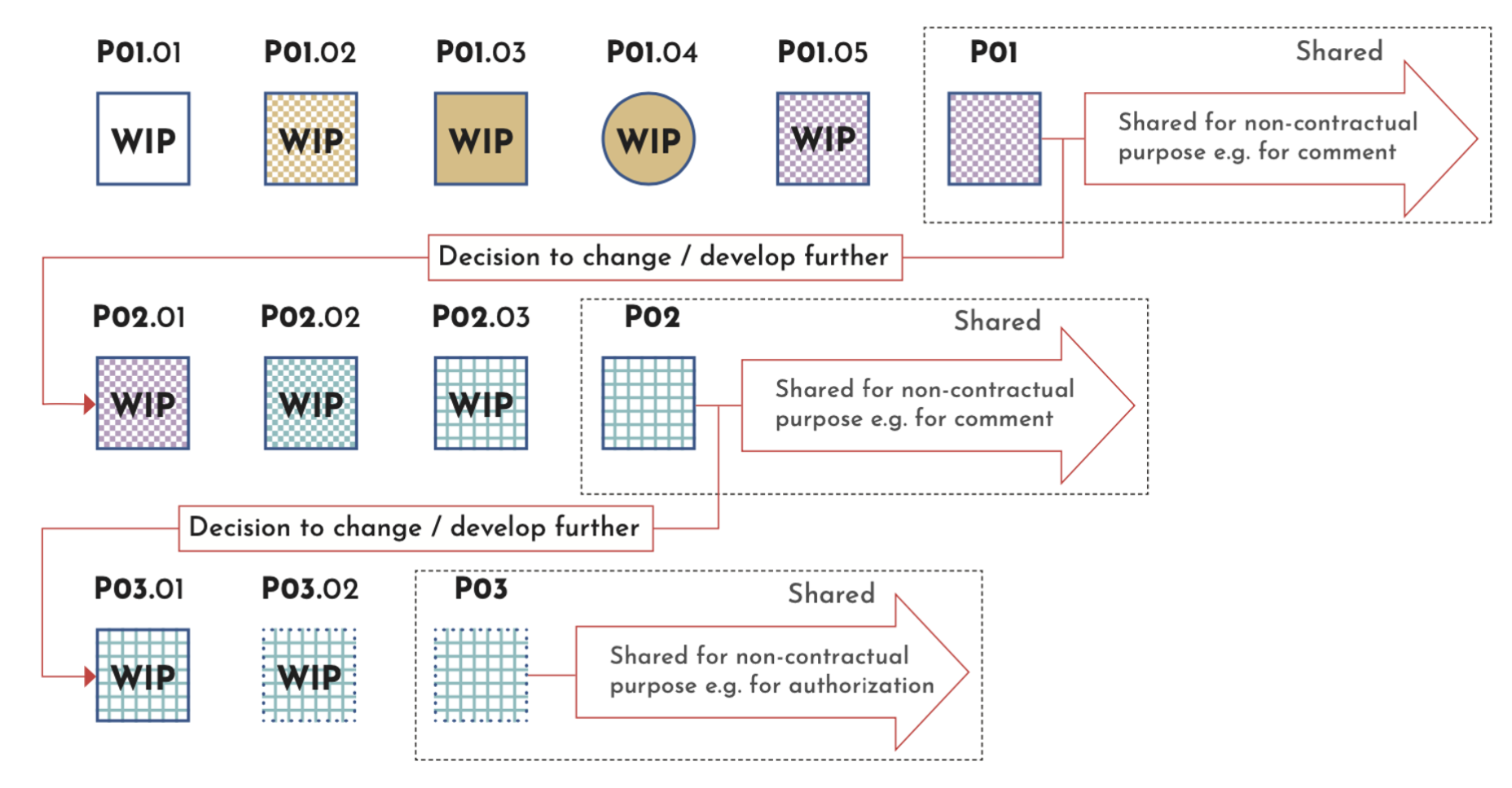
ISO19650 has a system of revisioning/issuing that involves interim revision between formal issues. It works on the basis of the issue you are working towards. It manifests as P01.01 where P01 is the revision you are working towards, and 01 is the interim issue, which could work in your particular case. You could therefore use a mixture of 'Issue' and 'Revision' in VW, where perhaps the formal Issue is P01, and the revision is A, B, C for internal review, e.g. P01A, P01B, etc All this of course assumes you are not being asked to issue documents in accordance with ISO19650. This diagram explains the concept... The 'P' standards for Preliminary or Work in Progress. Under ISO19650 if you see an issue/revision 'C01' the 'C' denotes 'Contractual' e.g. Issued for Tender.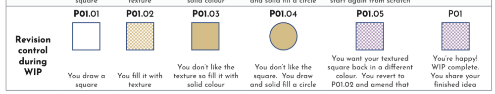

-
A native revit file will not be georeferenced when opened in VW. The georeferencing settings in revit are an applied coordinate system not a native one. Always ask for IFC.
-
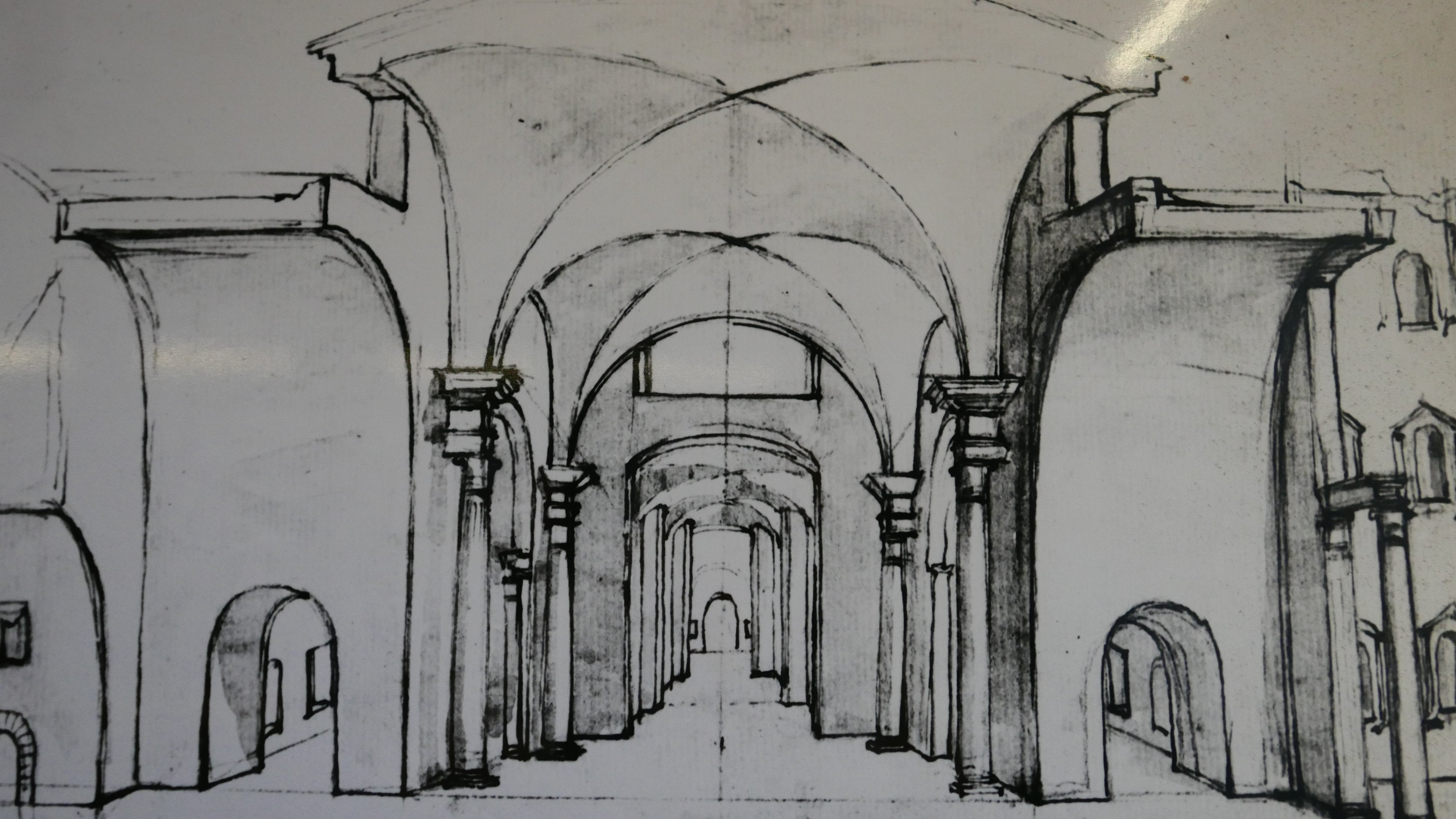
Build the profile and shell. How would VW be able to do this... https://stantonwilliams.com/en/works/the-age-of-chivalry?tag=exhibitions That said, a dedicated ceiling tool at all would be nice.
-
I should also add that we have identified a bug in Revit where the location of the internal origin will move if the rotation angle is set AFTER the location of the project base point. Creates havoc when trying to coordinate IFCs.
-
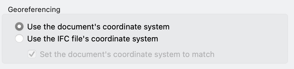
When you say 'geo-referencing' you aren't using the document setting, are you? You need to do some coordination testing and this all depends on what they have sent you as a base. Have they issued an IFC in OPS coordinates or not, and is it rotated or not. Based on the screenshot (and I assume that coordinate is rounded not precise) you need to leave geo-referencing well alone, and simply set the 'user origin' to the coordinate given. Test 1 Try opening a new file, and test an import of their IFC and reference the resulting VW file to your model. Also, check their IFC has been issued correctly by opening it in BIM Collab or SOlibri first, and checking the 'location' of the project. If the location X and Y values are not as per the screenshot, then they have not exported it correctly. 1 Set the user origin as follows (assuming I have read the coordinate correctly) https://www.dropbox.com/t/kZPVVbNt47Vv5v8o 2 Then import the IFC with these settings: 3 Check the IFC, delete any unwanted data, rename classes and layers with the author code otherwise they may conflict and then reference it to your model, which if it is set up correctly should align the IFC to the internal origin in your model (use layer referencing and 'ignore source user origin'. If the IFC has been issued from 'shared coordinates' all should be well. The rotation angle is a red herring. You will need to use rotate view to align your model to theirs if they send it from shared coordinates. If they have sent you an IFC from 'internal cooordinates' then the process is a bit easier. Test 2 Import the IFC into a fresh file, without setting the user origin. The origin in the IFC and orientation of the model should be as per the screenshot. If you or the architect need any assistance, get in touch offlist. The coordinate and rotation angle in the screenshot suggest they may need assistance.
-
Oh dear.
-
It is good practice to align all three at the start of the project. The critical point is the internal origin. Ideally this would be aligned to the PBP and Survey Point. If the Revit users want to change the location of the PBP after, it will have no impact on coordination as the PBP is peculiar to revit. However, make sure the PBP does not set a faux level unless agreed. Models must be built at the same level relative to the internal origin and a level should not be applied to the PBP in Revit unless agreed (e.g. when the buulding is up a mountain, you establish a common datum and agree that ground floor FFL = 0m in the model = 1000m AOD. It is possible to cheat and issue a model that counteracts the effects of a faux level applied at the PBP if one is applied without agreement but it's not ideal. We often end up creating multiple models to issue to different consultants because they do not know where their origin is and it's too late to do anything about it.
-
there is a process called 'proof of concept' that must be carried out before any meaningful exchange of data, even in 2D. Write the following (or similar) into the project BEP... "Proof of Concept stage (aka Coordination Testing Stage) As good practice, ensure these procedures are followed, and that a coordination test is carried out before any modelling commences: 1. All models shall be built from fresh template files. 2. Do not use ‘Save as’ to create a new model. 3. Do not use models that have been upgraded from older software versions. This is to avoid potential corruption due to the upgrade process or from previous modelling processes and configurations. 4. Following the setting up of the discipline model, either via incorporation of the coordinating DWG, RVT or IFC file issued by the Architect, test models shall be shared according to the procedures and processes outlined in this BEP and the accompanying documentation. 5. Do not commence any modelling until a coordination test has been carried out and signed off by the Architect and Project BIM Manager. The test will be successful when models from all consultants have been shown to align without editing to Internal Origins and Shared (i.e. Site) XY Coordinates, and thus they can be linked, referenced, or imported by Internal Origin as well as Shared Coordinates."
-
Do you need these for 2d, 3d, or coordination?