Tom W.
-
Posts
5,156 -
Joined
-
Last visited
Content Type
Profiles
Forums
Events
Articles
Marionette
Store
Everything posted by Tom W.
-
Man if you can do one that would be amazing. It should definitely be possible. My experiments have it repeating over insane distances though + I just don't have the maths/geometry knowledge/brainpower to figure it out. I'm trying a much simpler more symmetrical version just to get something that works... I would love to know how you'd approach something like this, just to get my head around it. This hatch for example has 980 levels!
-
Don't worry I'm still here scratching my head what a nightmare! I qualify my previous statement: I figured out how the hatch editor works, which was great for a moment, until I realised how profoundly unsuitable it was for making the kind of pattern I'm after...
-
ok panic over I figured it out phew
-
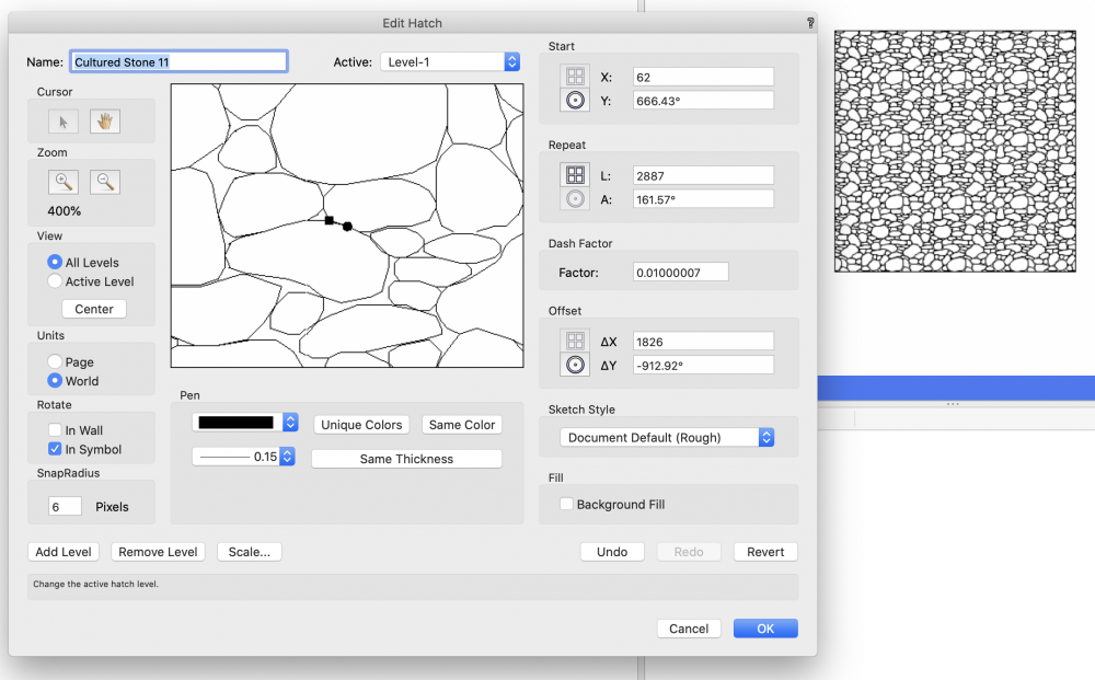
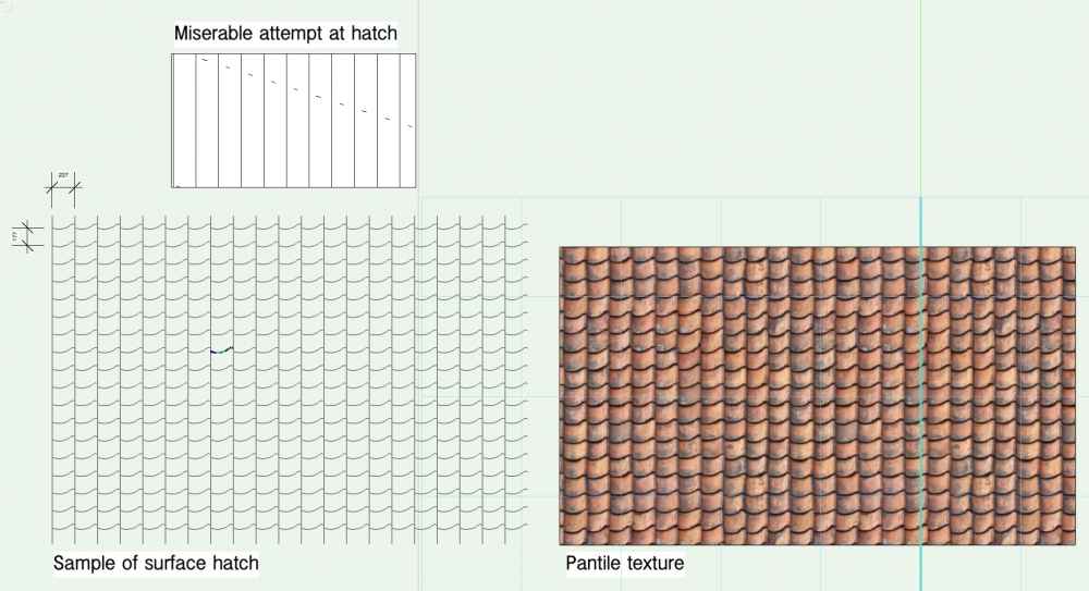
This thread has prompted me to have a go at something I've been meaning to do for a while which make a hatch to go with a clay pantile texture. However I now realise why I put off doing it for so long. I understand in principle what I need to do but I'm really struggling to understand the relationship between the lines in my sample drawing bot left + the 'start', 'repeat', 'dash factor' + 'offset' settings in the edit hatch dialog. I have dissected existing hatches + done endless playing around with the parameters to try + understand how it works but am getting nowhere. I divided my curvy line into individual straight segments but I have no conception of how many levels will be required (or how I'd work this out) or how to translate the parameters for the lines in the drawing into the edit hatch settings. I am quite happy spending the time building the levels if I knew how I needed to do it. Normally you can figure these things out by trial + error but not in this case for me at least... Any guidance gratefully received Thanks
-

Linestyle of a wall - non-uniform outline of a connected wall
Tom W. replied to Grzegorz Krzemien's topic in Architecture
No problem glad I could help 👍 -
Linestyle of a wall - non-uniform outline of a connected wall
Tom W. replied to Grzegorz Krzemien's topic in Architecture
@GRZEGORZ you need to edit the wall style + set the pen thickness in the wall attributes to 0.35: On the subject of the Pillar command depending on what exactly you're doing it may be advantageous to use the Create Wall Projection command instead. A Pillar is a separate object whereas a Feature In Wall object is part of the wall geometry. But neither method is wholly satisfactory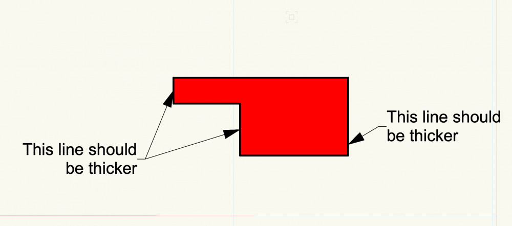
-
I'm not sure. I'm relatively happy with how the tool deals with the number + nature of components in a wall. The component wrapping works quite well in 2D: you can pick how many components inside + out you want affected + manipulate them in Top/Plan with blue handle to get them where you want them. And you can position the window wherever you want it within the thickness of the wall. The issue for me like I say is the complete lack of options in 3D + sections. The window tool I find quite useful for quickly adding windows to basic as-existing drawings where I've got a solid (single-component) wall + I just want something the right size + position + indicative of how it looks rather than an exact representation (so I won't bother showing sills). When it comes to an actual window that I want to represent 100% accurately I came to the conclusion that given the amount of work involved + the shortcomings regarding reveals, sill, etc I was better to model my own window from scratch + save it as a symbol than try + do it with the window tool. Then I could incorporate sill + reveals into the symbol + use wall hole component to clip the wall as necessary. But then obviously each symbol would be specific to a particular wall style so they'd be one-offs but at least they'd be correct + look right in all views + in section. I have a couple of projects coming up where I will try this but not done it so far so somewhat theoretical at moment
-
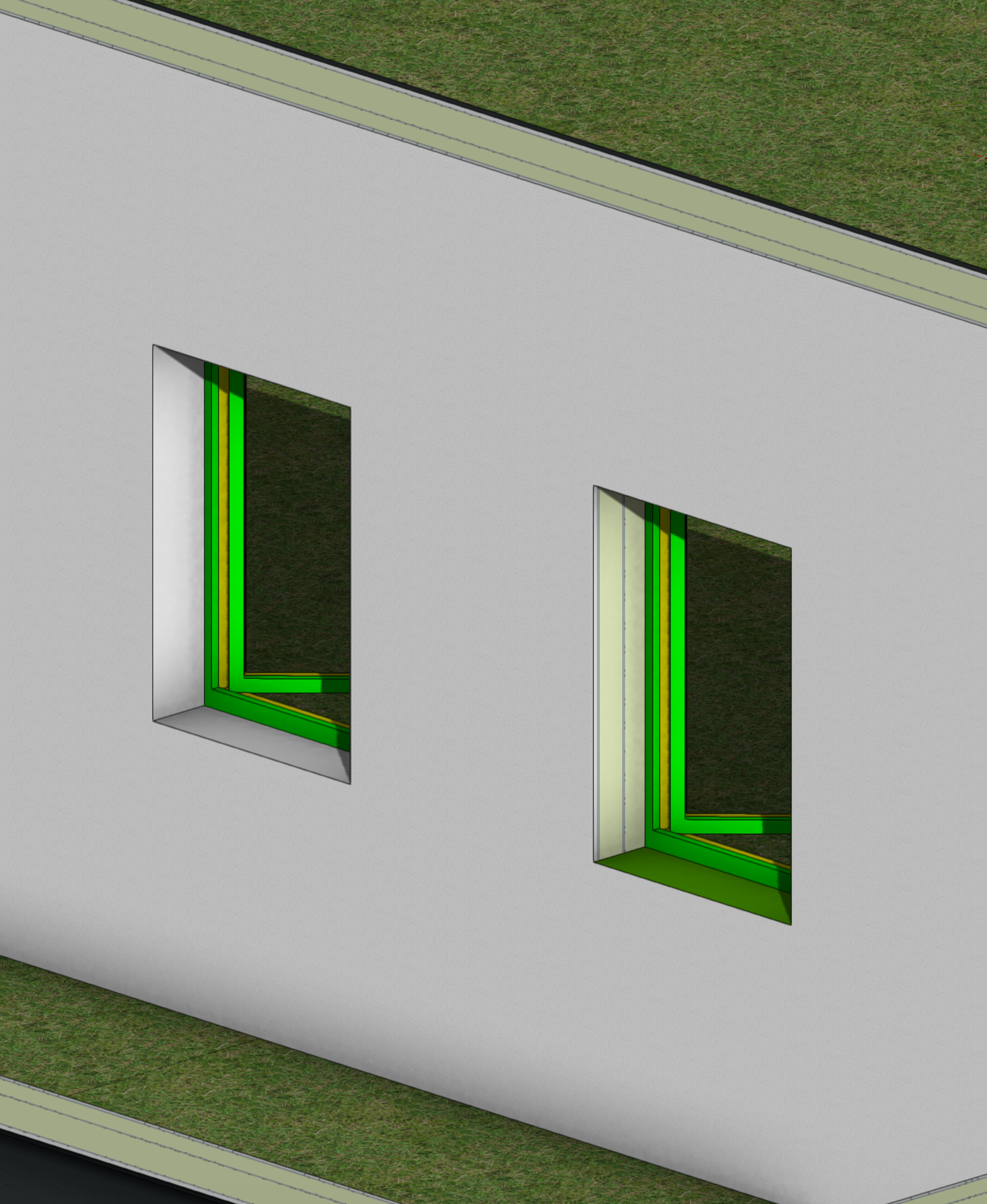
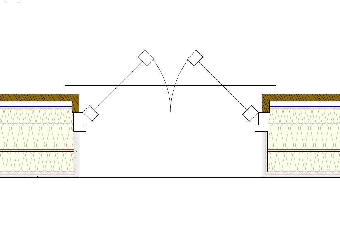
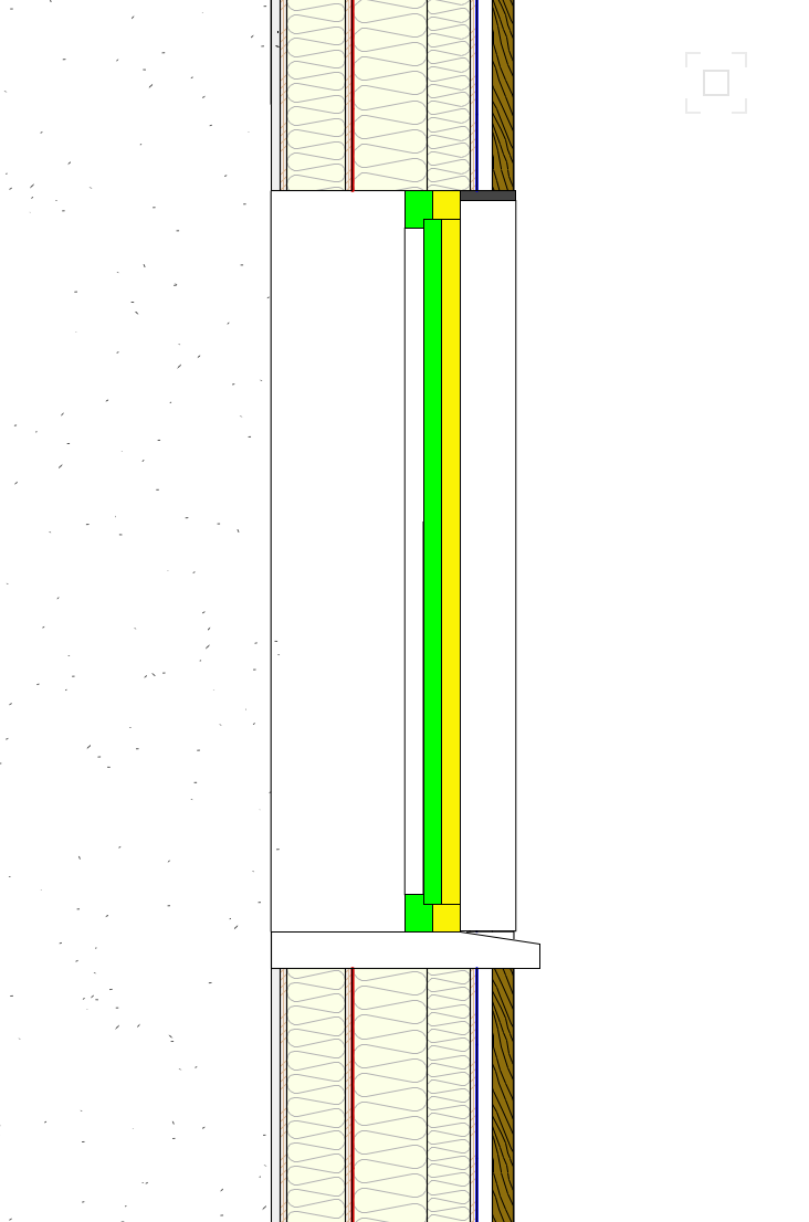
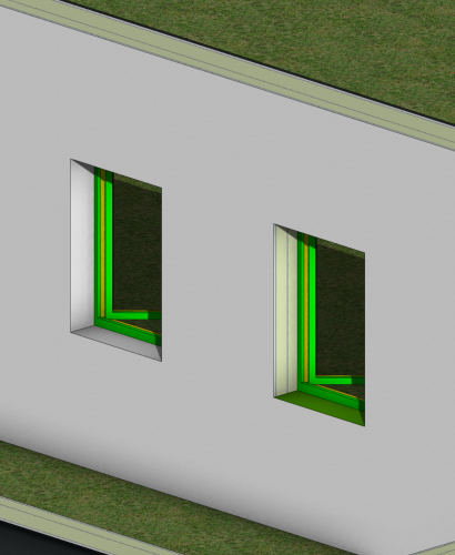
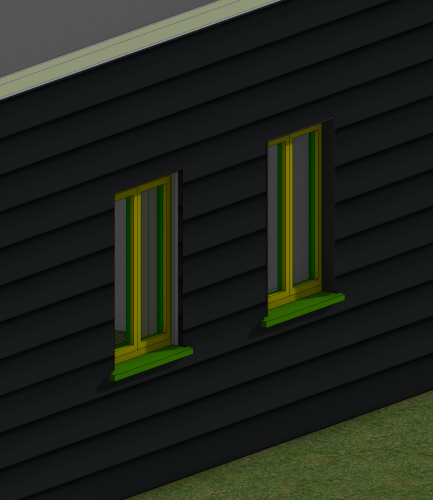
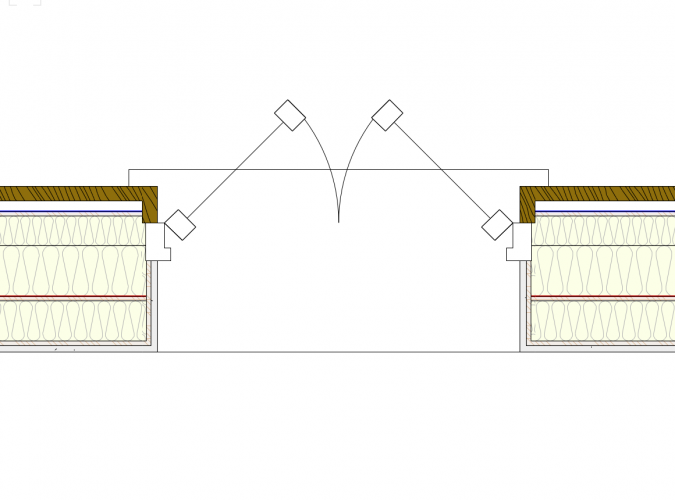
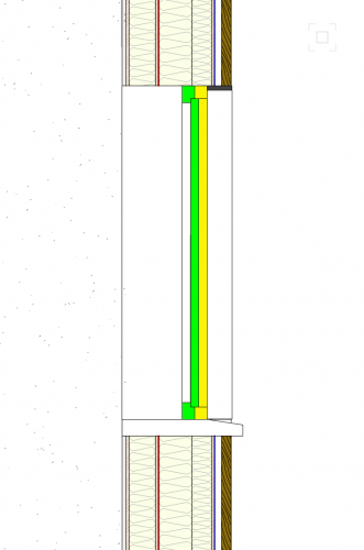
@LeeElston the window tool is a nightmare. You're correct the sill depth (4) is measured from the inside face of the wall + there's nothing you can do to move the back of the sill away from the wall. So if your wall is 300 thk + you want the sill to project beyond the external face of the wall by 40 you need to enter 340 for the sill depth. I set the Height (3) to something like 60 + the Sill Lip (1) to 40 + then the Keep (2) value is what determines where the slope on the top surface of the sill starts - and this relates to where you are positioning your window within the thickness of the wall: how far the front of your jamb is from the inside face of the wall. I enter something like 40 for the Extension (5) + don't bother entering anything for Stool Lip (6) or Stool Nose (7) as this just gives you a really crude internal window board planted on the face of the wall: you're better modelling something separately if you want a window board. In terms of the window's position in the wall it comes in centrally by default + you need to use the 'Plan Wall Offset' setting to move it in + out. So you can with extreme fiddling get a semi-ok looking window + sill but what really amazes me is the lack of options for wrapping the wall components around the reveals/head/sill. See screenshots. You can get the window looking ok in 3D by modelling your own reveals: The LH window has a 1mm thk extrude along path lining. The RH one is the same window with nothing added. You can see the green sill. Again the RH window has an extrude around it, the LH one nothing. You can get it looking ok in Top/Plan by wrapping the components in the 'Exterior' + 'Interior Wall Detail' sections ('Number of Components'). But you need to put the manually-drawn reveals in their own class + turn them off as you don't want to see them in 2D. But in vertical section you've had it: I am quite new to 3D so maybe I've missed something. To me, an accurate vertical section through a window is a fairly crucial piece of architectural information but if you want one in VW you need to draw a separate detail by hand as the model won't give it to you. Be keen to hear from more experienced people
-
Scale / Fixed position not proportional - yes I 've read instructions
Tom W. replied to DSmith2300's question in Troubleshooting
I agree with @scottmoore the best way to scale a group of objects from the centre is to use the Modify > Scale Objects... > Symmetric By Distance command. And don't be like me + ignore for years the little dims buttons to the side : they allow you to quickly take dims direct from the drawing which speeds up the process considerably! Or just use 'Symmetric' option + add a factor of 0.5 or 2 to half or double the size of the group or by whatever factor you want. Again, will scale from the centre by default.
-
To do it without converting the Roofs to Roof Faces you can increase the eave overhang of the second roof to extend it into the main roof then in Top/Plan view create polygons of the two roof shapes + use these polygons to clip the two roofs one at a time along the line where they intersect (Clip Surface command). Jonathan Pickup has some good videos on this which explain it better.
-
Hi @lisagravy thank you yes I was trying to import geometry from one georeferenced VW file into another - and guess what, I tried it again just now + it worked! So I must have done something stupid the first time: probably like you say neglected to check 'edit properties after creation' + set the imported layer to be georeferenced. I was just transferring some boundary lines I'd drawn on one OS map onto a larger map of the same area in another file. I have been importing georeferenced DWGs successfully (following the excellent instructions you posted elsewhere I should add!) + referenced DLVPs too - so was a bit disconcerting when what should have been the simplest thing out of all these - copying geometry from one file to another - didn't work. Good - thank you Good to know about the layer import referencing method as well
-
I may have misunderstood what you're asking but you can slope a slab hardscape of course to have it follow the terrain in a simple way or for more complex manipulation you can use an aligned slab hardscape + click on 'Edit Surface Modifiers' + use the stake + grade tools to really go to town on it. But ultimately you're still dealing with a series of flat planes rather than following the curvature of the terrain so this might not be what you want. What are the materials you are seeking to represent + how would they be constructed in reality?
-
Hi @Tamsin Slatter I am working with a georeferenced map + everything is set up correctly (user origin + internal origin). I want to import georeferenced geometry from another file. If I go down the Organization>Design Layers>New...>Import Design Layers route the geometry comes into the file way over at the user origin not at its correct georeferenced location close to the internal origin. But if I go down the layer import referencing route you suggest above it comes in at the right place. I am quite happy doing it this way but I'm interested to know why it doesn't work the first way + if I'm doing something wrong. Thanks
-
Ok that makes more sense thanks for explaining. Is the issue not simply the fact that Hidden Line rendering is black + white by default? So whilst a hatch may have a line or fill colour, once it's assigned as a Surface Hatch it will by definition only show as black + white?
-
@Stéphane I'm not sure what you mean by 'Line' render mode either can you post a screen shot? Surface Hatches only come into play with Hidden Line rendering. I'm not sure why you'd specify a Foreground Render but no Background Render. In my understanding Background Render is the default + Foreground Render only comes into play when you want to do something like overlay Hidden Line over Open GL as in @markdd 's example - no?
-
Your video looks to be showing the correct behaviour for the snap loupe. It is really only an aid to ensure you are clicking on the right snap point. Your cursor needs to be pretty close to the point in question when you press Z because the zoom area is quite small. Once you click on the point the loupe disappears + you automatically return to the drawing. It's not designed for doing any more than clicking on a tricky snap point. It is not an alternative to zooming in properly. You can hit Z more than once to zoom in further still if your snap points are really congested. Hit ESC to leave the snap loupe without clicking on anything.
-
polyline end point
Tom W. replied to gabrielefx's question in Wishlist - Feature and Content Requests
Actually the 'K' key. But phonetically correct! Works on walls as well -
Hi @WANA what you can do is start off with a Top/Plan VP then stack a second one on top: the second VP would be in Hidden Line + just have the roofs on it. So the roofs will display with the hatches but everything else will be 2D.
-
view object while in editing mode VW2021 - Colors control
Tom W. replied to Christian Fekete's topic in General Discussion
Doesn't unchecking 'Gray other objects' achieve what you're looking for? -
Is it literally a 'Guide'? Or otherwise locked?
-
@derred This post might be useful if you've not already seen it:
-
A surface hatch only displays in 3D. In OpenGL you see the texture; in Hidden Line you see the surface hatch. The surface hatch is like a black + white line version of the texture. Top/Plan is a 2D view so here you see whatever 2D attributes you've assigned to the objects. In your case hatch fills. So in your images the top row is Top/Plan view (2D) + the other two rows are Top View (3D). What's confusing is the surface hatch displayed on the middle left hand object: you should check the paving texture you used on the bottom LH object + see what surface hatch is assigned to it as it looks like you need to change it from the clay tile one to a brick one. If i've understood your images correctly
-
What's the best way make a second DTM to provide overhead fill like this? One site model at a time has kind of been enough for me so far but I'm interested to understand how you go about combining or stacking them... Like if you had a basement that projected beyond the footprint of a building. Thanks
-
Surface Hatched Baked into Textures
Tom W. replied to Jim Smith's question in Wishlist - Feature and Content Requests
It would be really good to do that + far more quickly/easily give a surface hatch to a texture -
That's a shame it would be so nice to have a bit more control over this detail, in 3D definitely but 2D too...☹️