cberg
-
Posts
834 -
Joined
-
Last visited
Content Type
Profiles
Forums
Events
Articles
Marionette
Store
Everything posted by cberg
-
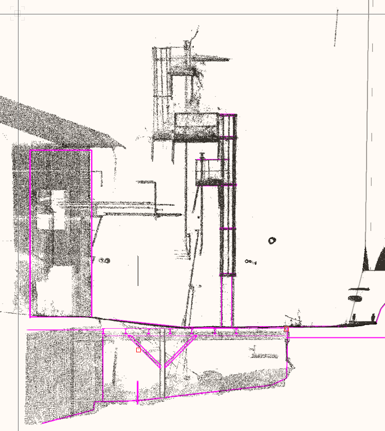
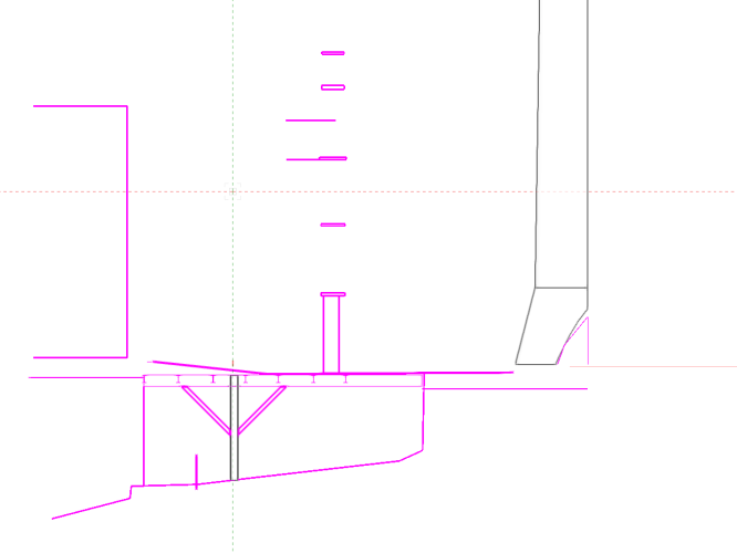
I am having issues getting dwg backgrounds out of Vectorworks after drawing over sections of a point cloud. I am working in VW2020 due to issues with rendering in future versions. As you can see from the attached screenshots, I've been able to section the point cloud, create working planes, and draw over the section in the active working plane to trace the outlines of the objects. In the model, some objects are 2d, and others are 3d. When I export the viewports from the sheet layers, only the 3d objects show up. What should I do to get 2d vector-based output so I can share this work with others and continue developing the drawing details? Maybe this is fundamentally a question about the relationship between 2d and 3d objects in Vectorworks. I would be fine, flattening the vector stuff so I can draw. But it would be better to continue to work in 3d so I can develop a model of the facility. Any thoughts as to best practices?
-
Point clouds seem not to render correctly in VW2022, viewports. I had to backsave all my models on my project to VW2020, for me to work with them. Not sure what is going on. I assumed it was something to do with the switch to the new Shaded Renderer that replaced Open GL.
-
availability - smartpaste for Vectorworks 2022?
cberg replied to matteoluigi's question in Troubleshooting
Any updates on Smartpaste? -
That makes sense. But not seeing them at a glance, makes them harder to find.... Any downsides to turning Unified View off from a performance perspective?
-
Just curious... Without disabling unified view, where do you do draw 2D details in the 3D workspace, especially if they are at different scales? We make layers just for 2d Details, various scales. This enables things to more easily move from file to file... One option is to make everything a symbol. But making everything symbols is a little confusing for the average user.
-
Interesting.... If the walls are on the same class, one can either duplicate or "copy and paste in place" and they will purge. If you switch classes or layers the walls won't purge.
-
@zoomer You probably know this.... On a test file, the command does seem to delete walls if they are duplicated in place. Probably when some slight modification is made to the wall, they are no longer exactly the same, and that is when the command fails to purge.
-
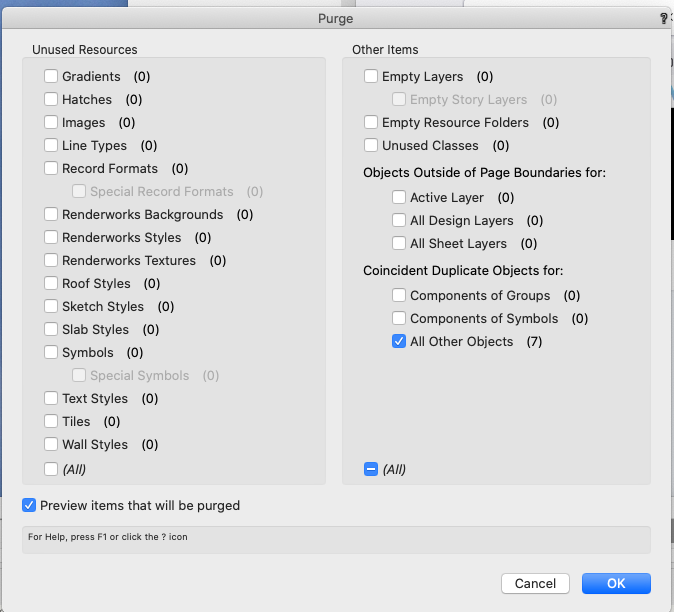
In the purge command you can delete the Coincident Duplicate Objects. Not sure how smart this will be and I would save your drawing beforehand....
-
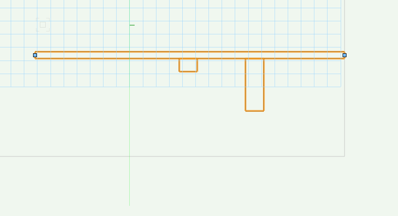
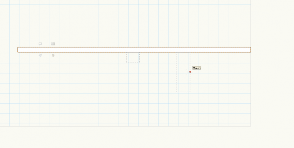
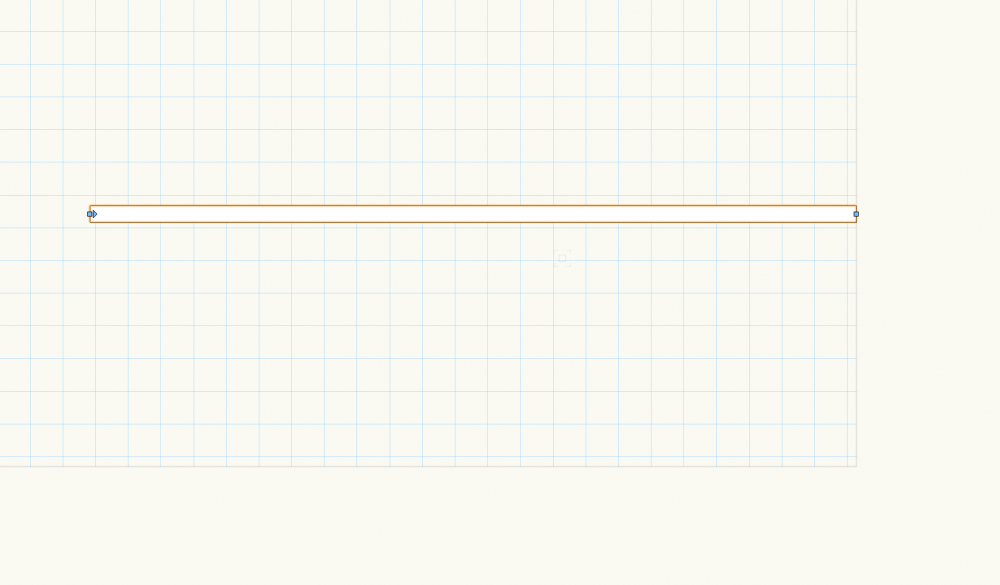
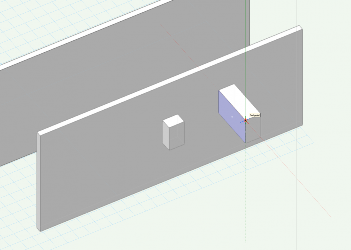
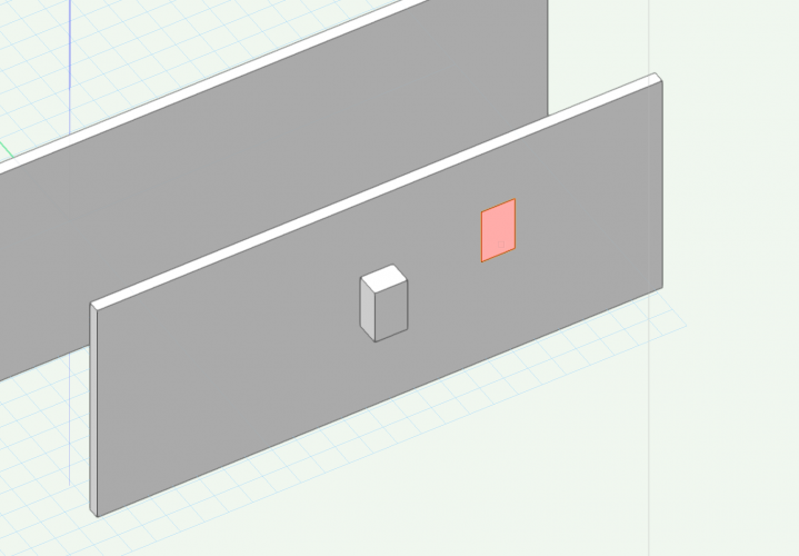
I'm not sure if this is a bug or a feature of VW2022... If you make a wall and then use the plane of the wall to make some sort of solid extrusion using the push pull tool, the resulting solid sticks to the wall. (Maybe this is the sculpted wall that the videos were showing). However these objects that are stuck to the wall have no edit behavior and no view control in 2d plan. (As wall recesses and projections do). Odder still, if you move, join or extend the wall the objects disappear. What exactly is going on? Bug or Feature? Test .vwx
-
@ChristiaanDoes that mean you model your exterior walls, interior walls, and structural elements on separate layers? Or would you divide out the exterior walls into two separate elements (framing + finishes)? Where do slabs and roofs fit into this equation? I'd be interested in learning more about how you organize your models.
-
Ohhh... It's an upside down cup of coffee!
-
I'm not going to say anything about the odd color selections.
-
Easier dimensions for sheet layer viewports :)
cberg replied to Kaare Baekgaard's question in Wishlist - Feature and Content Requests
Both of you are correct. It is super cumbersome to always click to enter the annotation space. But once contained viewports do function as a useful organizational tool. How about splitting the difference? What if there was a key command or some other shortcut to enter the annotation space using a single command? If you could break out the functions separately, then all the clicking could be turned into a programmable key command or mouse click.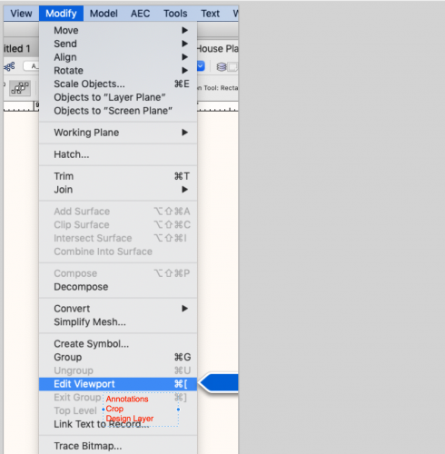
-
It would be great if the Detailer tool were somehow included in the Ozcad Tools Package.
-
Probably the best thing to do is to cut the crop rectangle and rotate the image. Then paste the crop rectangle back in place.
-
Wishlist - Custom automatic viewport naming
cberg replied to Gregovitch's question in Wishlist - Feature and Content Requests
In one of the VW2021 change logs, I saw that they fixed that bug. I haven't had any issues in VW2021. https://release.vectorworks.net/nnapub/updaters/26/NNA/eng/meta/releasenotes/SP3.html
-
Quitting a command can't happen until modeling functions use multiple cores. While this functionality has been promised for years, when it gets implemented is anybody's guess. Developers probably have to rewrite a lot of code to make this happen.
- 1 reply
-
- 2
-

-
Wishlist - Custom automatic viewport naming
cberg replied to Gregovitch's question in Wishlist - Feature and Content Requests
Here is a VW2020 file with the actual script embedded. As mentioned above, you access it through a custom folder in the Resource Manager Scripts Pulldown Menu. Rename Viewports.vwx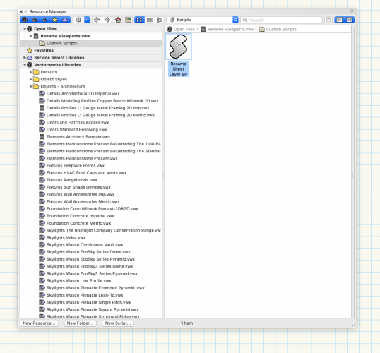
-
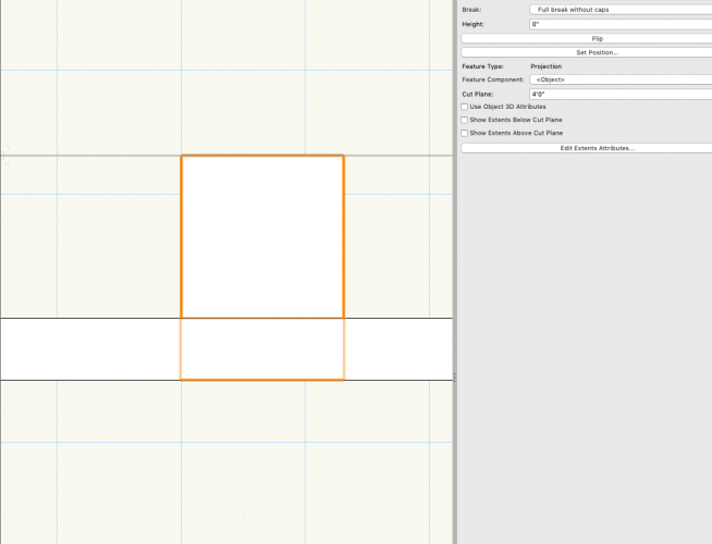
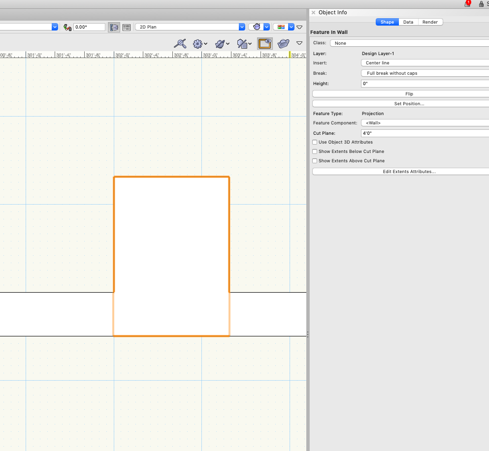
I agree with @zoomer that wall projections are not very good and there are problems at corners. @trashcan Not sure if your question was answered. If the feature component is the object, then a line appears. If the feature component is the wall, then it merges with the wall in plan 2d. There's a dialogue box to control this.
-
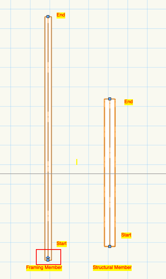
I've always used framing members instead of structural members, and now I remember why.
-
As an aside, and I may submit this as a bug. This is one of those annoying VW quirks and what drives users of the program crazy. The structural member tool doesn't indicate the start of end point of the member. The framing member tool shows an arrow. Unless I am missing something, there doesn't appear to be any way to graphically understand the start and the end points of the structural framing member.
-
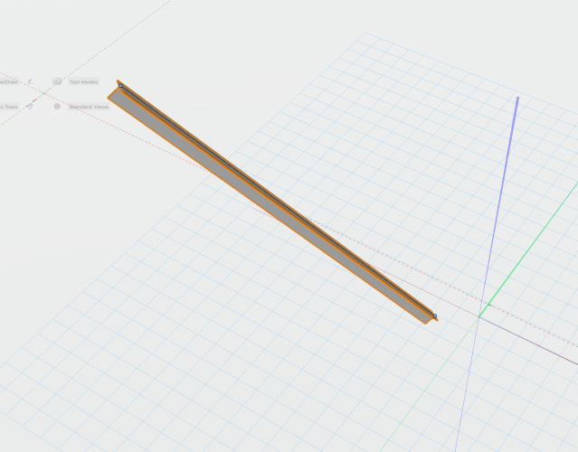
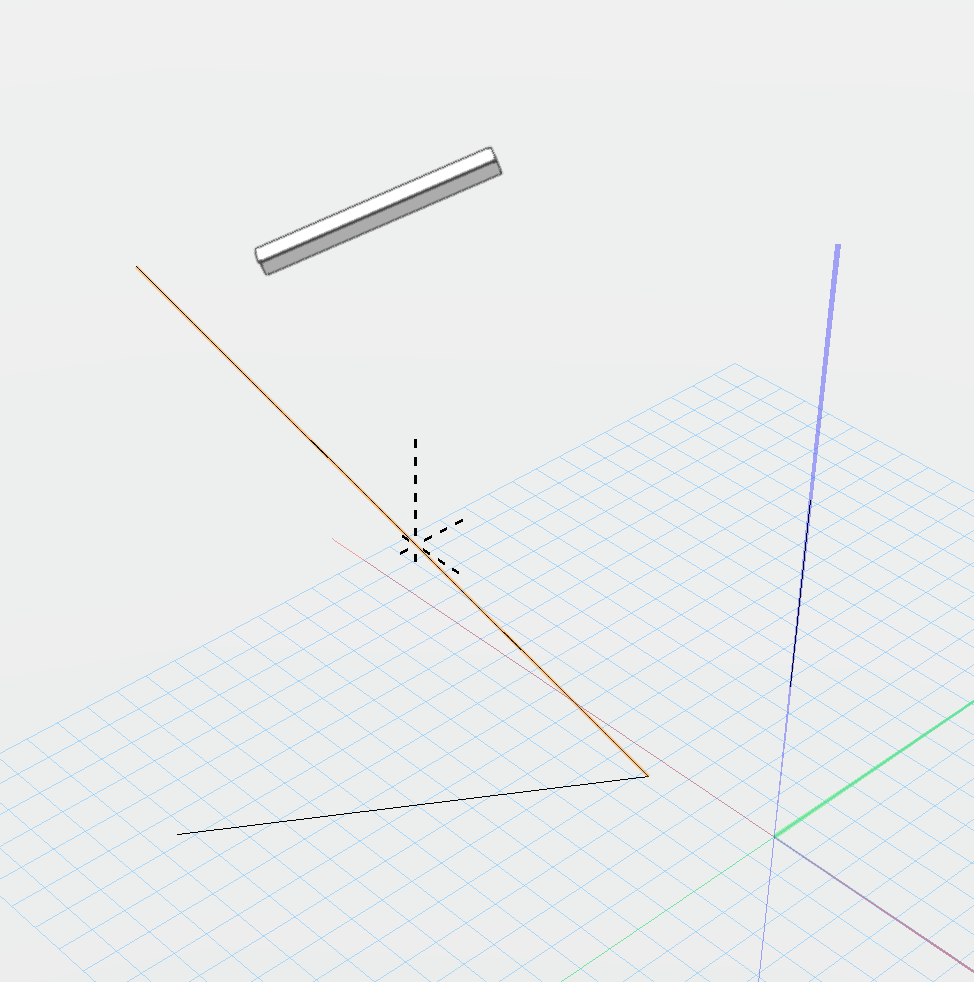
I figured it out. It is easier to do this with the structural member tool.... If you know the Z axis elevation, then you can manually enter it, and not worry about the angles
-
Is there a good way to align a framing member to the the highlighted line? I'm sure there is some trick to setting up working planes or something like that. I am having trouble getting the angle between the two lines. Which would then establish the pitch of the framing member. Test.vwx
-
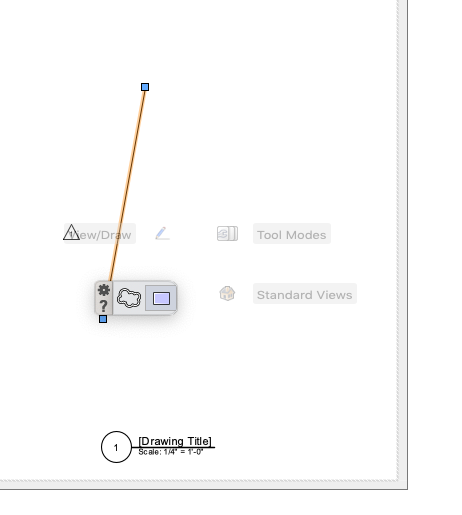
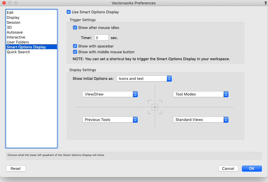
This may be a "feature," or this may be a bug. Nevertheless it is annoying. If you use a tool in an annotations viewport, it does not show up in the "Previous Tools" list that pops up via the "Smart Options Display" interface. In the file below, I created a Revision Cloud and Rectangle in the Design Layer. The Line and the Revision Marker were made in Viewport Annotation. When the Previous Tools are activated, only the design layer objects show up in the list of recent tools.
-
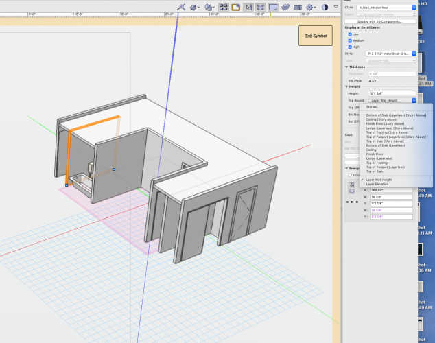
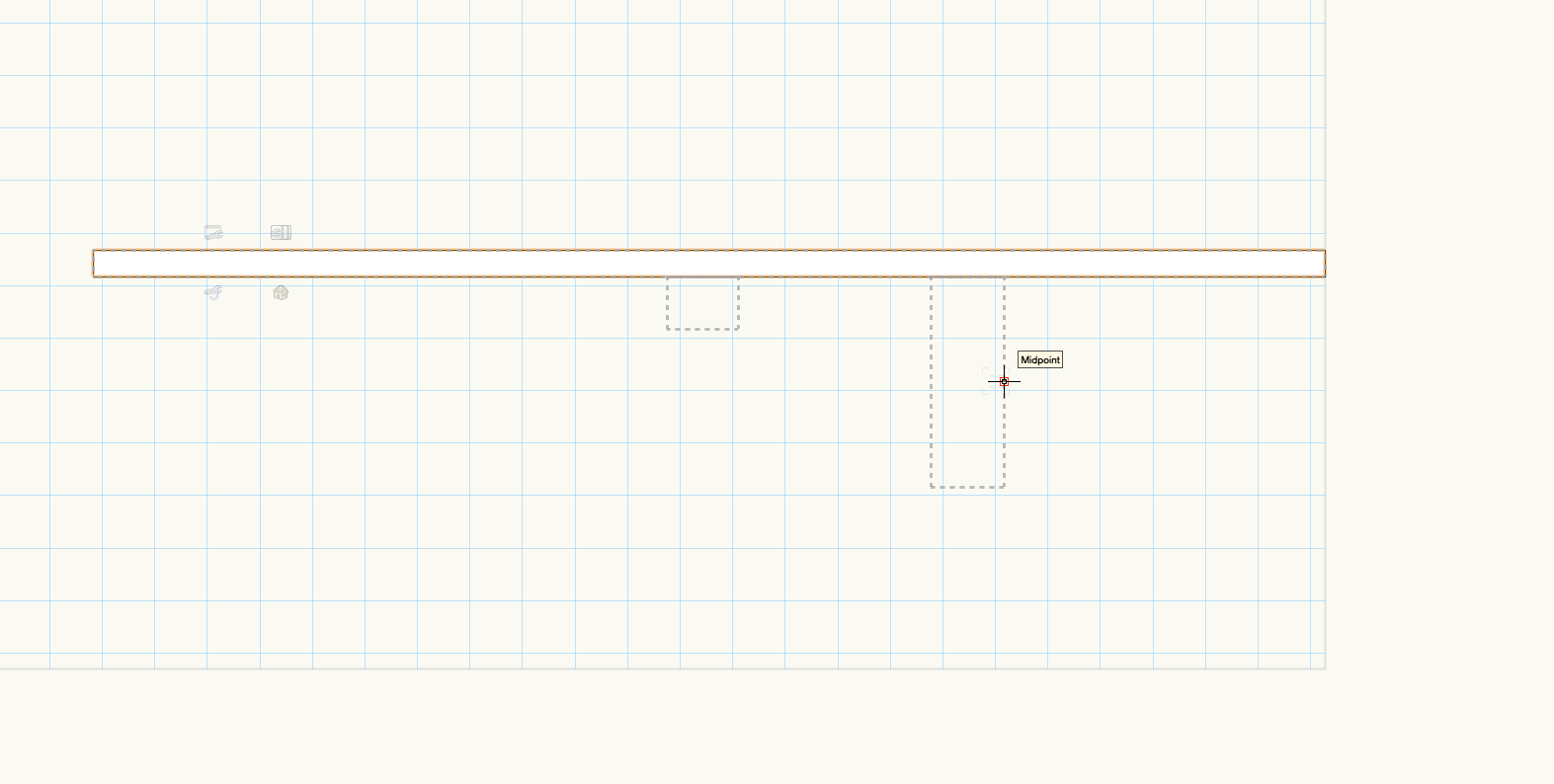
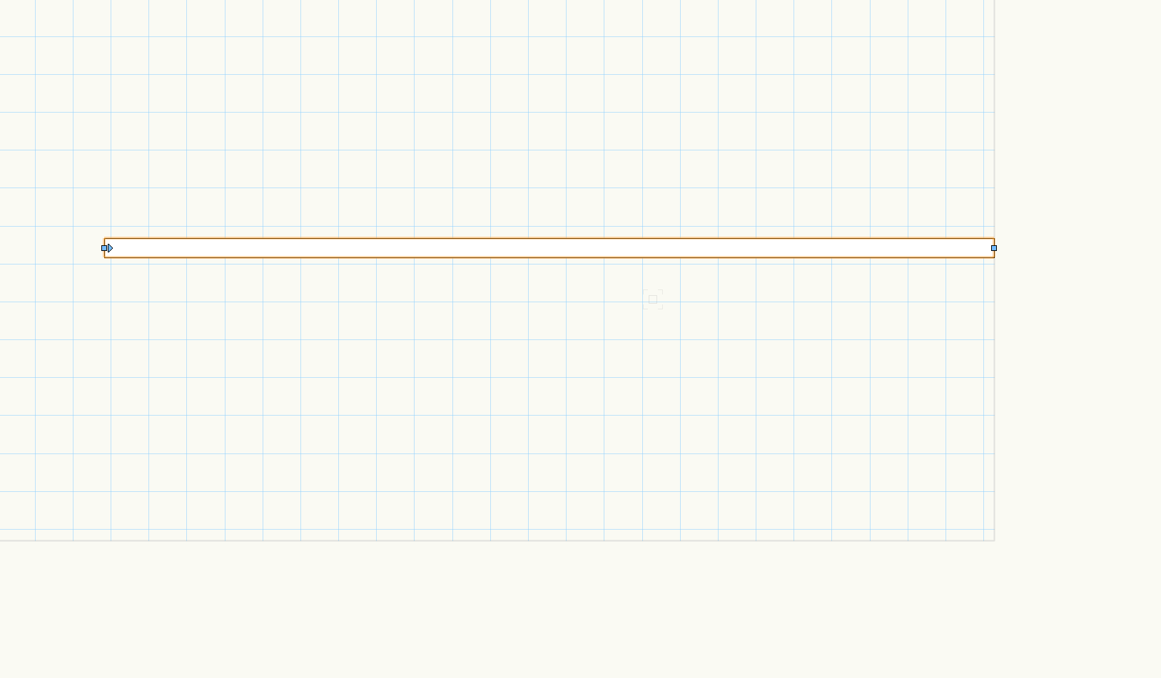
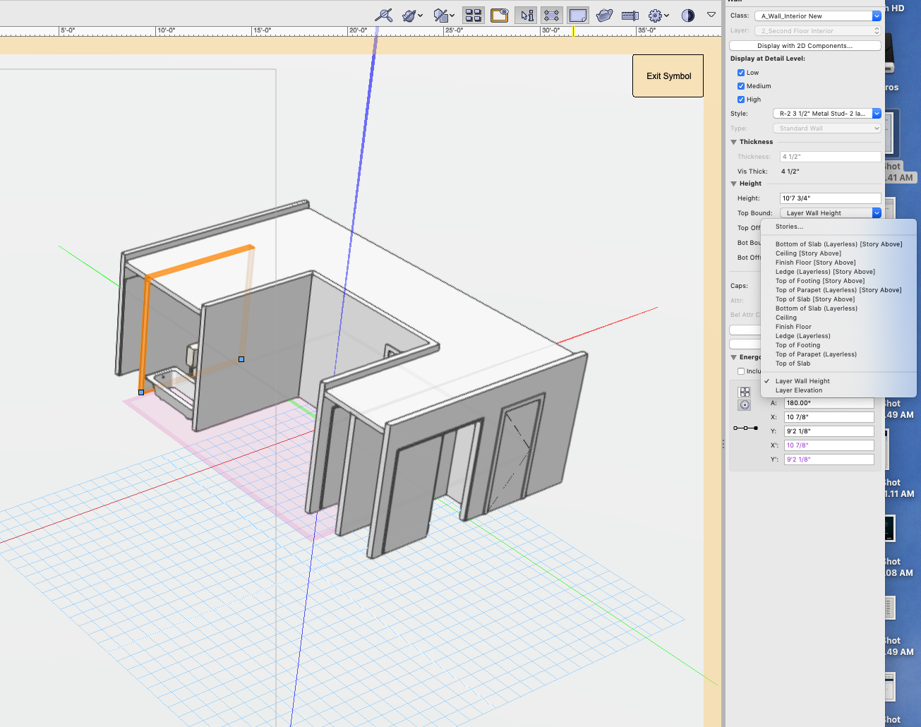
This thread shows the need for unit plans, which are discussed on this site elsewhere as a Development Roadmap Item. The only workaround to this solution that I have discovered is to ungroup the symbol and redefine it, once the wall edits are made. I personally have not figured out a way to adjust wall heights in symbols, which is kind of a pain. (edit: I guess offsetting the components does do the trick) VW Development Team, it would be useful to have another mode to establish the wall height top and bottom. Layer Wall Height, Layer Elevation, Symbol Definition. That way the walls would be defined by the Z-axis of the symbol.