


MullinRJ
-
Posts
2,007 -
Joined
-
Last visited
Content Type
Profiles
Forums
Events
Articles
Marionette
Store
Posts posted by MullinRJ
-
-
I just placed your script into a Menu Command, placed that command in my Custom Menu, and assigned Cmd-Shift-9 to it. It works without the extra overhead of having to click in the drawing. I think that initial click is a built in penalty required when using tools vs. menu commands. You have to click in the drawing for the script to run. If using a hotkey for a menu command instead of a tool does not rail against the tenets of your core beliefs, may I recommend giving it a try to see if it will work for you?
HTH,
Raymond
-
SP3 or SP4? I just remembered there was a bug in SP3 where the ALT keys for tools did not work. It seems to be fixed in SP4. If you're still on SP3, I recommend you upgrade to SP4.
I'm using SP4 with OPT-9 set to your New Round Wall tool. When I press OPT-9 it almost sets the tool up, as the name shows in the Tool Bar, but none of the button icons appear. After I click once in the drawing, then the tool's mode buttons appear. When I click the second time I can draw with the New Round Wall tool.
I'm on a Mac, so the behavior may be different on your PC, but it's still not working the way I expected to. Can you describe in more detail what's happening your end?
Raymond
-
@WhoCanDo, I just found out the cutoff for the tool numbers is VW 2022 and older use -318 for the Round Wall, while VW 2023 uses -208 for the Wall tool, but the second mode is now the Round Wall tool.
Now my question is, what version of VW are you running? The same command SetToolWithMode() can be used in any version of VW from 2016 onward, but the tool number and the mode buttons you set will change in VW 2023 and beyond, compared to the ones you would use before VW 2023.
If your signature is correct, then you will want to use:
SetTool(-318); { Round Wall Tool }
SetToolWithMode(-318, 1, 1); { Group 1, Selection 1; ie Left Control Line Mode }
In VW 2023, and presumably newer, use:
SetToolWithMode(-208, 1, 2); { Group 1, Selection 2; ie Round Wall Mode }
SetToolWithMode(-208, 2, 1); { Group 2, Selection 1; ie Left Control Line Mode }
Raymond
-
Appendix E, after the color palette.
Raymond
-
I got them from the VS Func Reference Appendix -> SetTool - CallTool Selectors. I used the HTML version that ships with the software, but it is also online in the Developers Wiki.
Raymond
-
I believe it could be done with a worksheet script. Build a Resource List of all worksheets in your drawing; step through each list element and filter the names to match your criteria; if a WS passes the filter, extract the value from cell A1 and sum it; return the sum from your function.
What say ye, @michaelk?
Raymond
-
 2
2
-
-
In older versions of VW use : SetTool(-318); { Round Wall }
In newer versions use : SetToolWithMode(-208, 1, 2); { Round Wall mode of the Wall Tool }
I believe you can set other mode buttons of the Wall Tool by changing the middle number to select the button group, and the last number to select the button within that group.I don't know what VW version is the cutoff version. One of these should work for you.
Raymond
-
Hi @Jiajing,
It seems to work on all container objects, as best I can tell. As you can see, it even works on symbol definitions. I think I saw @Julian Carr use it once in an unexpected way a couple of decades ago, and I've been using it ubiquitously ever since. It's never caused a problem, so I keep using it. It's my magic can opener.
Raymond
PS - Thanks, Julian.
-
1
-
-
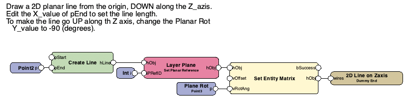
Follow up. I just figured out you don't need the Layer Plane node if you don't use Enable Legacy 2D features (starting VW 2022), or you use Working plane only. If you mix Screen and Working Plane objects in the most recent VW versions, then the Layer Plane node makes sure the line draws on the Layer Plane. If there's an easier way to force Layer Plane drawing, please let me know.
Raymond
-
I think @Marissa Farrell's way is the way to go, but if you want to see how to draw a 2D Line on a vertical plane (YZ plane in this case), I cobbled together a few Marionette nodes to draw a Planar 2D Line that runs from the Origin (0, 0, 0) down along the Z_axis. This is not guaranteed to be the smallest node, but it works. Suggestions for improvement are welcome.
You can change the Line's length by editing the Y_value of the 2D point (pEnd) on the Create Line node. You can also change the Start Point by adding a 3D Point to the vOffset input of the Set Entity Matrix node and giving it any 3D XYZ value.
NOTE: All unassigned input nodes use the value (0, 0) or (0, 0, 0). The attached VW file is v2018, so more people can read it.
Vectorworks file: 2D Line on 3D Plane v2018.vwx
Raymond
-
To get a handle to objects inside a Symbol Instance, you have to take a more circuitous route. First, symbol instances are not container objects. The real container is the Symbol Definition. To get a handle to a Symbol Definition when you start with a handle to a Symbol Instance try this:
# return a handle to the first object inside a symbol definition where H points to a symbol instance
if (vs.GetTypeN(H) == 15):
	SymDefName = vs.GetSymName(H)
	SDefHnd = vs.GetObject(SymDefName)
	InsideH = vs.FIn3D(SDefHnd)


vs.Message(InsideH, '  ', vs.GetTypeN(InsideH))
or you can express it in one line:
# return a handle to the first object inside a symbol definition where H points to a symbol instance
InsideH = vs.FIn3D(vs.GetObject(vs.GetSymName(H)))
Raymond
-
1 hour ago, Pat Stanford said:
I think you mixed up threads Raymond. This was the select similar fixtures not the split text thread.
Yep, too many stars in the left hand column, and they keep changing positions. I obviously clicked on the wrong thread. I'll correct the previous script in a moment.
Thanks, Pat.
Raymond
PS - My second script posted above is now corrected to reflect the topic in this thread.
-
There may be an easier way to select the first selected object on all visible & editable layers, but I know this way works and it avoids any confusing side effects of using ForEachObject(). So here is a version that will let you select an LD on any layer, then the script will select all similar LDs in the drawing.
Here's the updated updated_version of the relevant script. (Apologies for any confusion caused by my earlier post.)
PROCEDURE SelPosFix;
{ Select all Lighting Devices that match the Position and Instrument Type of the selected LD. }
{ 05 Mar 2023 - Raymond J Mullin }
{ 06 Mar 2023 - Added a procedure to select an object on another layer. Script will still select similar LDs on all layers. }
CONST
	RecName = 'Lighting Device';
	Fld1 = 'Position';
	Fld2 = 'Inst Type';
VAR
	Hd0 :HANDLE;
	Pos0, Typ0 :STRING;

	function FSVisEdObj :Handle;
	{ Return a handle to the first Selected and Visible object on Editable Layers. }
	Var H :Handle;

		function GetIt(H1 :Handle) :Boolean;
		Begin  H:=H1;  GetIt:=True;  End;	{ GetIt }

	Begin 		{ FSVisEdObj }
		ForEachObjectInLayer(GetIt, 3, 0, 4);	{ Visible & Selected Objs, Shallow, Editable Layers }
		FSVisEdObj := H;
	End;		{ FSVisEdObj }


BEGIN
	Hd0 := FSVisEdObj;
	if (Hd0 <> nil) then begin
		{ save values of selected object }
		Pos0 := GetRField(Hd0, RecName, Fld1);	{ Lighting Device . Position }
		Typ0 := GetRField(Hd0, RecName, Fld2);	{ Lighting Device . Inst Type }

		DSelectAll;

		{ select all objects matching the original selected object. }
		SelectObj(INSYMBOL & INVIEWPORT & (R In [RecName]) & (RecName.Fld1 = Pos0) & (RecName.Fld2 = Typ0) );
		SysBeep;	{ make noise when done }
	end		{ if }
	else AlrtDialog('Select an object and rerun script.');

END;
Run(SelPosFix);
Raymond
-
Hello @unearthed,
I thought you would have had an answer by now. Since that didn't happen, I cobbled together a script that will split lines into text blocks. It could have more refinements, but I assume that is not necessary. Let me know if this works for you. And if you want the original text block to disappear after it is split, uncomment line 46 near the bottom. (See comments.)
PROCEDURE SplitTextToLines;
{ Split selected text block into individual lines at each Carriage Return. Each line becomes its own text block. }
{ Original text block gets deleted if user uncomments the DelObject() line at the end of the script. }
{ 06 Mar 2023 - Raymond J Mullin }
{ NO WARRANTY EXPRESSED OR IMPLIED. }
{ USE AT YOUR OWN RISK. USE ON A COPY OF YOUR DATA FIRST. }
CONST
	CR = chr(13);
VAR
	H :Handle;
	Mirrored :Boolean;
	X, Y, Ang, LineSpc :Real;
	S, T :Dynarray of Char;
BEGIN
	PushAttrs;

	H := FSActLayer;

	{ create new text with these attributes. }
	TextVerticalAlign(2);			{ top baseline }
	TextJust(1);				{ left justified }
	TextSize(GetTextSize(H, 0));

	{ get the text, its insertion point, and the line spacing }
	S := GetText(H);
	GetTextOrientation(H, X, Y, Ang, Mirrored);
	LineSpc := GetTextSize(H, 0)/72;	{ approximate }

	{ make sure text ends with a carriage return. }
	if (S[len(S)] <> CR) then
		S := concat(S, CR);

	{ split lines here }
	while (len(S) > 0) do begin
		T := copy(S, 1, pos(CR, S)-1);
		delete(S, 1, pos(CR, S));

		if (len(T) > 0) then begin
			MoveTo(X, Y);
			CreateText(T);
		end;
		Y := Y - LineSpc;
	end;		{ while }

	{ **** Uncomment following line if you wish to delete the original text when done. **** }
	{DelObject(H); }

	PopAttrs;
	SysBeep;
END;
Run(SplitTextToLines);
Raymond
-
2
-
-
Hello @spettitt,
There are some syntax errors in your script (missing ";" after DSelectAll), and some logic errors (procedure Execute never executes). Rather than massage your script, I'm posting a script that I think does what you want. If it is what you want, use it as a template to create similar scripts, or modify it further as you deem fit. If you want something different, please explain further.
PROCEDURE SelPosFix;
{ Select all Lighting Devices that match the Position and Instrument Type of the selected LD. }
CONST
	RecName = 'Lighting Device';
	Fld1 = 'Position';
	Fld2 = 'Inst Type';
VAR
	Hd0 :HANDLE;
	Pos0, Typ0 :STRING;

BEGIN
	Hd0 := FSActLayer;
	if (Hd0 <> nil) then begin
		{ save values of selected object }
		Pos0 := GetRField(Hd0, RecName, Fld1);	{ Lighting Device . Position }
		Typ0 := GetRField(Hd0, RecName, Fld2);	{ Lighting Device . Inst Type }

		DSelectAll;

		{ select all objects matching the original selected object. }
		SelectObj(INSYMBOL & INVIEWPORT & (R In [RecName]) & (RecName.Fld1 = Pos0) & (RecName.Fld2 = Typ0) );
		SysBeep;	{ make noise when done }
	end		{ if }
	else AlrtDialog('Select an object and rerun script.');

END;
Run(SelPosFix);
One note of caution, in your original script you used the variable "Pos", which you can legally do, but "Pos" is a VS function name that returns the position of a substring from a target string. If you don't expect to use that function, no foul, but if you try do use both in the same script there could be some confusion headed your way. In the example above, I added a "0" to the global variable Pos0, and a "1" to the local variable Pos1. This will avoid all future conflict with predefined terms.
HTH,
Raymond
-
1
-
-
Peter,
Did you select Python Script in the popup menu at the top of the Script Editor? If it's set to VectorScript it will definitely error.
Raymond
-
1) Check out this link and read what Robert Anderson wrote several years ago. I think most of it is still relevant.
2) Open the Plug-In Manager and create a new plug-in – type Command, it's the top choice. Give it a name, and click Enter.
3) Next, click the Edit Script... button and paste your script code here. Select Vectorscript or Python and click OK.
4) Next, click the Edit Definition... button and select the Properties tab. Here you and add a Tool Tip to describe your command when you hover over it with the cursor, and set any restriction on how it executes. Mostly, NONE is acceptable, unless something needs to be selected.
5) Click OK, then click Close.
6) Wash – Rinse – Repeat for each script you want to immortalize.
Are you familiar with the Workspace Editor? If not, write back if you need help to add your new commands to a menu.
Raymond
-
You can save your master file as a template (.sta) and when you open new files using that template your scripts will be included. Use menu File > Save As Template...
OR
You can create Menu Command plug-ins from your scripts with the Plug-in Manager (Shift-Cmd-Z), which are subsequently added to the VW interface with the Workspace Editor (Option-Shift-Cmd-W). Hot keys can be assigned to your scripts in the Workspace editor so you can quickly access them, too. This is the more tedious route, but the more flexible one
If you need help with either of these options, please write back.
Raymond
-
I'm going to describe the manual way first.
1) Create your symbol with geometry AND a text field. The text can have anything in it as it's just a place holder at this point.
2) Create a Record Format with one field (type text). The default you type in for the record will be the default text you see when the symbol is placed in the drawing. It can be blank.
3) Edit the symbol and select the Text object. Select menu item Modify > Link text to record... Choose the new record format and the field and click the OK button.
4) Exit the symbol.
5) With the symbol selected, open the DATA pane of the OIP. Select the record format (if there are more records attached to your symbol), and change the text to the right of the field name below. You may have to adjust the pane dividers to see everything. Press ENTER and your new text will display next to your symbol. You can now change the text in the OIP for each symbol in your drawing without affecting previously placed symbols.
Putting these steps into a script can be done, but it is more difficult. Off the top of my head I don't remember exactly how it's done, but I've done it before, so I know it's possible. Write back with more questions.
Raymond
-
1
-
-
The same applies for =T, for the column header. CSG and Generic Solids will both show as CSG Solids.
-
1
-
-
The object type is the same for CSG and Generic Solids (84). I doubt worksheets can see the difference if they are just sorting by Object Type. @Pat Stanford may know better, so wait for his answer.
After some quick testing, if your column header in a database row is =ObjectTypeName, you will see things like Extrude, Solid Addition, CSG Solid, etc. It appears the label CSG Solid refers to Generic Solids, while solid objects that have an editable history will be labeled by the outermost solids operation.
if you just use =ObjectType for the column header, then you will see "84" for CSG Solids and Generic Solids. Other solids like Extrudes (24) and Sweeps (34) will show their respective object type numbers.
HTH,
Raymond
-
1
-
-
Hi Peter,
As I understand it, CSG Solids contain history, while Generic Solids do not. CSG stands for Constructive Solids Geometry, which implies it is made from operations with other Solids. With the solid's history, you can enter a CSG Solid and see what composes it, like Solid Addition / Subtraction operations, and/or Filleting / Chamfering operations. Each of those can subsequently be entered and edited. Then you can back out to see the result. With Generic Solids you cannot enter them to perform any edits. You can only scale, and rotate them. I assume the memory requirements are much less for Generic Solids, though I've never compared them.
HTH,
Raymond
PS - I just tried this to confirm – you can use Generic Solids in subsequent Solid Operations. So, a CSG Solid can contain solid primitives (like extrudes, etc.), other CSG solids, and Generic Solids.
-
I see what you mean by your code not working when a design layer has a z-offset. I have written a utility plug-in, Reshaper, that gets and sets object parameters. My Reshaper code and your code and the OIP agree when objects are placed on layers without a z-offset. Reshaper and your code also equally disagree withe the OIP when there is a layer offset, so you're basically doing things correctly. There may be a bug that needs to be exposed, but a workaround would be more useful.
I have not tested my Reshaper code under these conditions, but I'm about to start. I'll keep you posted as I learn what's really going on, assuming I do.
Raymond
-
2
-
-
Do you need to ungroup it? You can scale symbols now, too.
SetObjectVariableInt(Obj, 101, 2);	{ ScaleMode: 1=None, 2=Symmetric, 3=Asymmetric }
SetObjectVariableReal(Obj, 102, 0.2);	{ X scale factor }
SetObjectVariableReal(Obj, 103, 0.2);	{ Y scale factor }
SetObjectVariableReal(Obj, 104, 0.2);	{ Z scale factor }
Symbols will scale around the Insertion Point. If you are only scaling symmetrically (ObjVar_101 = 2), you only need to set ObjVar_102 (X Scale Factor), as all symbol axes will use that value.
If you do need to ungroup it —> What@Pat Stanford said.
Raymond
-
1
-
Script to automate Worksheet options when counting Symbols ie: More Choices
in Workflows
Posted
Hi Peter (@Elite Exhibits),
Do you need to see the symbol thumbnails, or just the symbol names, in a list when you are making your choices? Your request is doable, but not necessarily easy. Viewing the thumbnails would be more difficult than just viewing the names.
Raymond