


WhoCanDo
-
Posts
402 -
Joined
-
Last visited
-
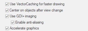
Zoom 3D screen image wrong after rotation
WhoCanDo replied to WhoCanDo's question in Troubleshooting
Thanks Pat, I had proposed too after inquiring for a solution, if it was available. -
Zoom 3D screen image wrong after rotation
WhoCanDo replied to WhoCanDo's question in Troubleshooting
Yes. Closing the file and opening it again does fix it. I don't need to close VW. The error re-occurs only after repeating the duplicate and rotation process again. The first duplicate and rotation remained constant but the second has the error. Files attached. Video Project 2.mp4 Zoom 3D screen image wrong after rotation.vwx -
"Do you want this app to make changes to your device." I get this message each time I start VW2024, by both starting the app directly, and by opening a file which opens the app. I completely uninstalled VW and reinstalled without luck.
-
Zoom 3D screen image wrong after rotation
WhoCanDo replied to WhoCanDo's question in Troubleshooting
VW2024 Zoom refresh error.mp4 This video is with the object at the origin. The first video was on a PC with Windows 10 and this one is on a laptop with Windows 11. There are no other similarities except they are the same version of VW The file is attached. Just follow the instructions and see if it happens for you. -
This has been happening in 2024 and can be quite difficult to work with. I created a 3D set of panels on the right and then picked the first panel and then duplicated it and rotated it to get the left side view. However, when you see the attached video, I am zooming in and out, and the top view flashes before returning to the side view. This is what is happening at the moment, but I also get the opposite. Sometimes I will do the same duplicate and rotate but end up with the top view, and I will only see the side view when I am zooming in and out. I've tried switching layers and back again, and choosing top plan view, but only closing the file and reopening it solves the problem. Any ideas ? Zoom Fault.mp4
-
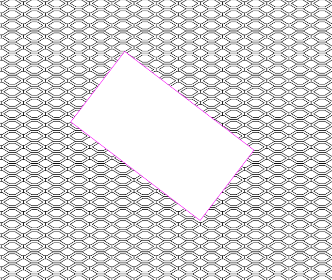
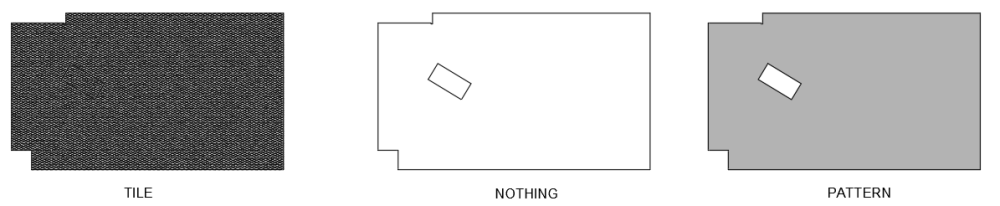
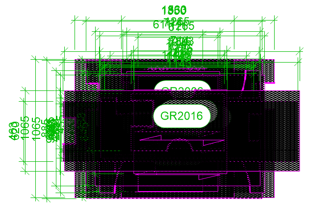
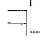
When filling with the pattern, the result is correct. When filling with a tile, I would expect something similar. The pattern should not cover the cutout.
-
There use to be and AutoCad help sub-section, but it disappeared. My problem is that I have created a tile and I use it to represent a product. If I create a 2D shape and another within, then I subtract solids and then tile it, after exporting to .dwg, the cutout does not appear (as below left). However, if I have no fill or a pattern fill, it does work (as below middle & right). These pictures are from AutoCad after the export to .dwg
-
Viewport location after creation
WhoCanDo posted a question in Wishlist - Feature and Content Requests
Hi, There was one version of 2024 in which, when a viewport was created, it's location was in a similar location to the Sheets Layer. ie. In my case I draw a frame around the viewport area that I want to create as a viewport. For every version except one (can't remember which one), the viewports all end up in the middle of the Sheet Layer and on top of each other. However, in one version, I remember being surprised that the first viewport was next to the second viewport, just as I had them on the Desing Layer. Mistake or not, it was very handy. Like this .... Not this ....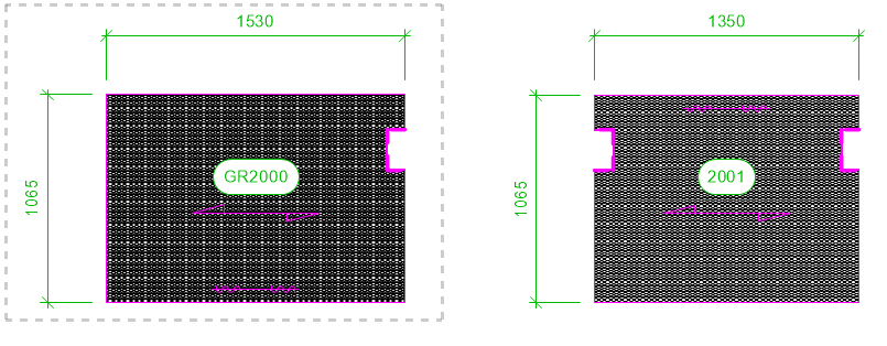
-
Viewport attached to object wish
WhoCanDo posted a question in Wishlist - Feature and Content Requests
Not sure how VW would approach this one, but AutoCad seems to be able to do it. When I draw something on the Design Layer, and I create a viewport, when I move something on the Design Layer, the viewport does not show as it originally did. eg. What was on the viewport .... What is on the viewport after I move the something on the Design Layer I move this left object -100, -100 on the Design Layer However, the object is in it's own viewport (a jigsaw piece). It is not associated with the 2nd viewport to the right. Obviously, if they were in the same viewport then I would expect this result. Somehow, AutoCad can make viewports of individual or selected objects and when they are moved, the viewport crop moves with it/them. This would be great to see in VW.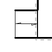
-
Hi, As far as I am aware, Vectorscript can't print a worksheet to a pre-defined filename - I'm printing to the "Microsoft Print to PDF" printer. Therefore, can anyone come up with an idea to copy text to the Windows clipboard so that it can be pasted into the filename box when printing it? With VS's "Print ('Worksheet Name')", Windows saving convention pops up, but the filename is blank. Since I already have files of the suffix format that I want, I would just click on an existing file and that would prefill the blank filename area, and then I want to paste in the prefix. eg. suffix = "This file.pdf", prefix = "Despatch List ", result = "Despatch list This file.pdf"
-
I just got word from Tech Support that they have seen this, and it is being looked into.
-
This has not been fixed in VW2024 SP3
-
This has not been fixed in VW2024 SP2 If all Windows users are experiencing it, then I will make an error report and hope that the answer doesn't come back that it was a Windows update that caused it and they can do anything to fix it. However, this only happens with VW.
-
Good news. Slow walls has been fixed in VW2024 SP2
-
Hi Alana, I agree. Unified view is not as good as it was. This may happen when the layers (if your using layers) are different scales.

