
Andy Broomell
-
Posts
3,178 -
Joined
-
Last visited
Content Type
Profiles
Forums
Events
Articles
Marionette
Store
Everything posted by Andy Broomell
-
Interesting, although I seem to get the exact same function/results when using the other mode too...
-
I remember trying to figure it out recently and still had absolutely no clue what it does. Would love to know.
-

Convert to Polyline Command
Andy Broomell replied to Kevin McAllister's question in Wishlist - Feature and Content Requests
I've probably wasted a few days of my life cleaning up results from Convert to Lines. Better commands would be most welcome. -
Audit a document? aka Something slowing me down
Andy Broomell replied to Ethan R.'s topic in General Discussion
As Kevin describes, the most easy aspect to address is the Segment parameter, which determines how ‘smooth’ the Sweep is. The number determines the angle of each segment (and therefore the total number of segments in the sweep... larger segment angle = fewer segments). Smaller segment angles create smoother sweeps, but also take up more memory and rendering time. Find the right balance so that the object looks good while still using the fewest number of segments possible. I often start with 20 and increase or decrease as needed. I seldom need anything as low as 5. Also, Sweeps with source shapes that have curves are more complex than source shapes with straight edges. If it doesn't need to be super smooth in your rendering/drafting, try building the 2D source shape with faceted edges or fewer points in general. Sometimes I use the 'Modify<Drafting Aids<Arc into Segments' command to break arcs down into a few straight lines. Of course sometimes you need a nice smooth object so it's not always applicable. -
Are you able to post a screenshot showing the uneven brightness?
-
I wonder if the following image in this morning's newsletter email might be indicating something along those lines? Hopefully it's not just another example of the marketing folks using images that are completely impossible to attain in Vectorworks.

-
Camera Viewport Fullscreen Help
Andy Broomell replied to Wesley Burrows's topic in General Discussion
Oh also - for this very reason I mapped Pat's awesome Perspective Crop Toggle script to one of the buttons on my 3Dconnexion mouse. It works like a charm and lets me effortlessly switch back and forth. I want full screen when designing/modeling, and cropped when setting up camera views. -
Camera Viewport Fullscreen Help
Andy Broomell replied to Wesley Burrows's topic in General Discussion
I'm crossing my fingers that this and other camera-related issues might be addressed in 2018. So many people use cameras and they could be soooooo much better. -
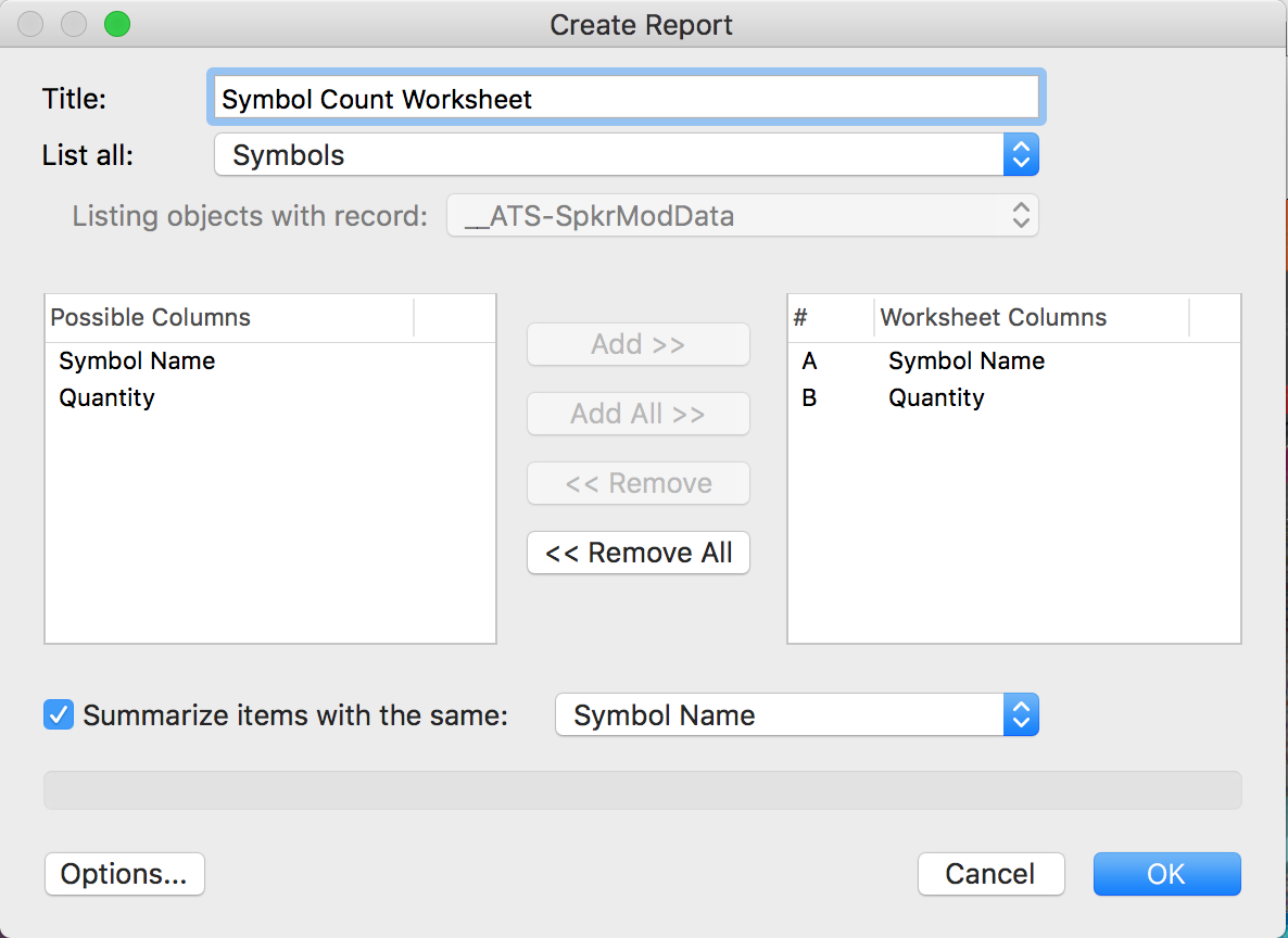
Start with Tools<Reports<Create Report. List all: Symbols. Click "Add All >>" button Check the summarize button. Click OK. This will at least get you started, though further work with record formats and/or other criteria would be necessary to break down the worksheet further. Have you worked with worksheets before?
-
Camera Viewport Fullscreen Help
Andy Broomell replied to Wesley Burrows's topic in General Discussion
On the first tab of Document Preferences there should be a checkbox called "Cropped Perspective" which causes this. Note that since it's a document setting, if you change the setting in one file it won't affect other files. If you always want it on or off, make sure to change the setting in your template file. -
Copying a selected area of a line drawing
Andy Broomell replied to Cadplan Architecture's topic in General Discussion
What is the end goal - 2D or 3D? On a Sheet Layer or Design Layer? -
Copying a selected area of a line drawing
Andy Broomell replied to Cadplan Architecture's topic in General Discussion
Also with a viewport, you can overlay things in the Annotations portion of the Viewport, especially for slight variations. This might be your best bet. Or have different classes displayed in different viewports to show the variations. Depending what you're doing, Classes Overrides can be helpful if the variations mainly involve changes in attributes (line type, color, fill, etc). They let you adjust the attributes of a class in that viewport only, and any objects 'listening' to that class will take on those visual overrides. Not sure how well this plays with wall components though... And again, not sure exactly what types of variations you're going for. -
Copying a selected area of a line drawing
Andy Broomell replied to Cadplan Architecture's topic in General Discussion
Also I'm assuming you need the actual geometry in the new design layer so you can continue working on it? If not, you might instead just want to use a cropped viewport to display the geometry on the second Design Layer (though the geometry won't be editable). -
Copying a selected area of a line drawing
Andy Broomell replied to Cadplan Architecture's topic in General Discussion
Hold Alt/Opt to select anything the selection marquee/lasso touches, rather than only the things completely encompassed by the selection. Of course this doesn't "crop" any objects down in the way a screenshot only captures a rectangular portion of your drawing. This will grab entire objects which you can then paste into your new design layer. After doing so, one approach might be using the Clip Tool in the second mode , then drawing a marquee over what you want to keep. This will delete anything outside of the box.

-
LED Screen Tool: Curved Screens
Andy Broomell replied to Andy Broomell's question in Wishlist - Feature and Content Requests
True, which gets us by for now . One thing that's nice about the LED Screen tool (and other PIOs) is that it automatically stretches the texture as you change the size of your screen. It's a major time saver and lets you focus on designing rather than texture mapping (which as we know is seldom fast and easy in Vectorworks). One other difference between the LED Screen tool and a Solid Addition is that the LED Screen tool allows you to still see the individual modules in wireframe, whereas a Solid Addition just looks like one solid mass. And in Hidden Line if I set my smoothing angle to 0° I can see the individual modules as well. This is helpful for construction drawings and drawings sent to video vendors.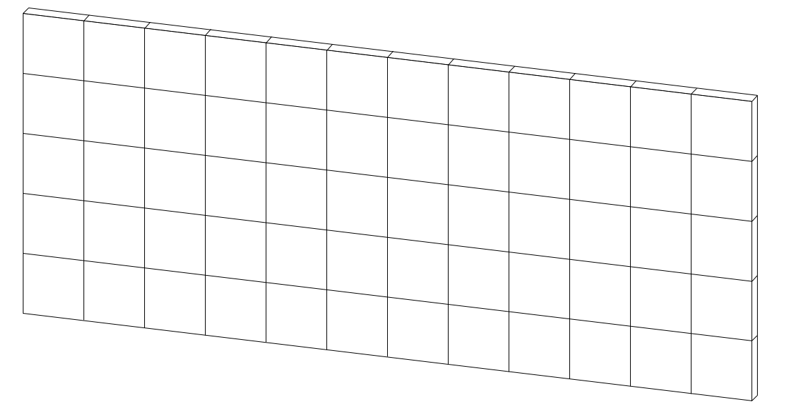
-
LED Screen Tool: Curved Screens
Andy Broomell posted a question in Wishlist - Feature and Content Requests
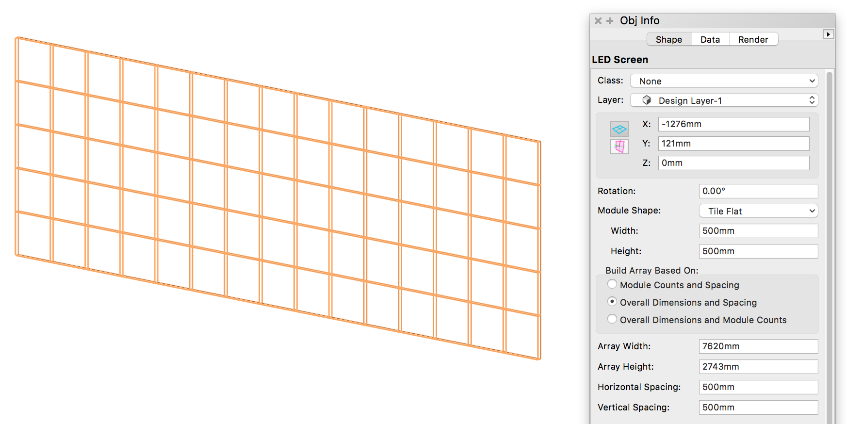
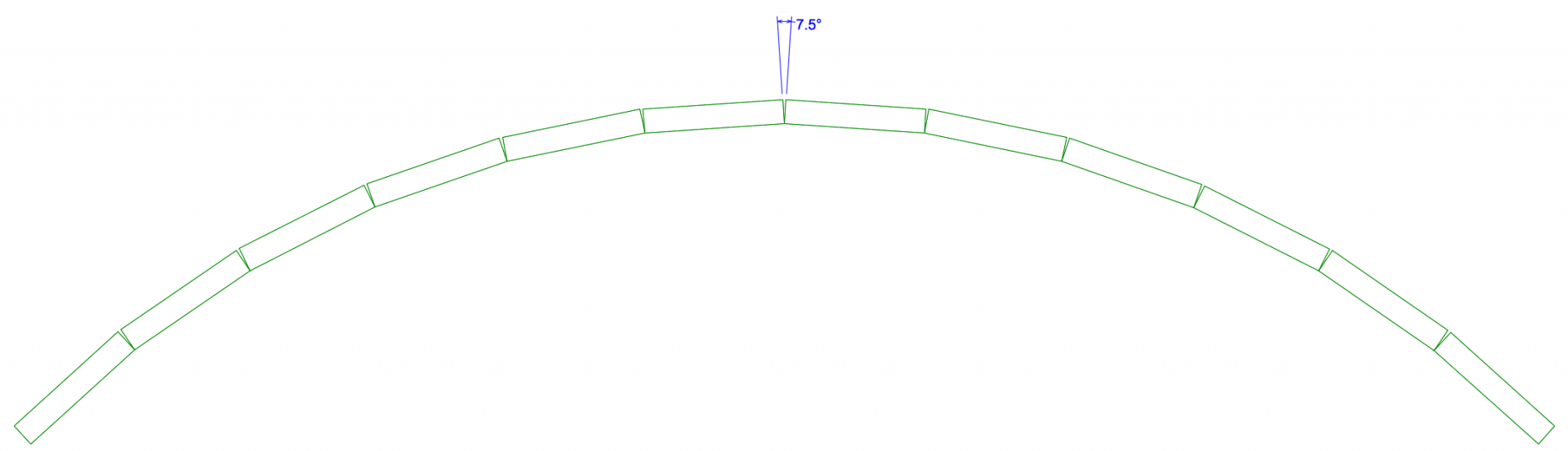
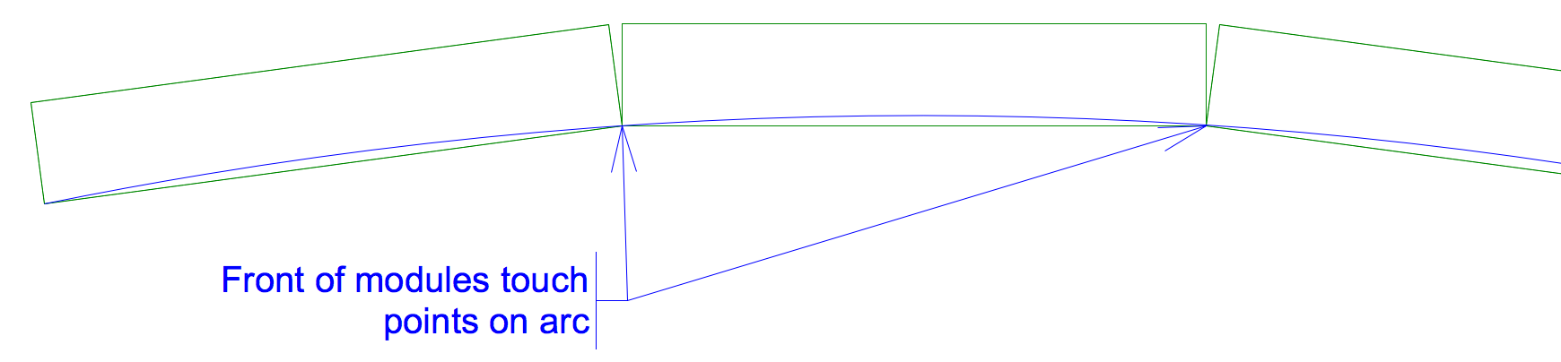
It would be great if the LED Screen tool had a way to create curved screens, such as this: Currently you can create flat screens with the LED Screen tool: Adding the ability to create curved screens could be accomplished by: Adding a parameter to specify an arc diameter Adding a parameter to specify an angle between each column of modules (a common approach since there's often specific curving block hardware available). For example, I could say I want 7.5° between each column of my 500mmx500mm modules. While I can model curved screens with simple extrudes like I did above, the LED Screen tool has many advantages, such as: Ability to extract data into worksheets. Flat screens and curved screens are all the same PIO. Built-in text labels. Automatic 2D representation with 2D solid fill. Mapping a single image texture across the modules. Automatic calculation of number of tiles within specified screen size. Most importantly... I can change from 500mm square tiles to 480mm square tiles and not have to start the whole process from scratch. Manually distributing the shapes accurately along the curve is a laborious process. If the LED Screen tool could do it all for me I would be a very happy camper.
-
I wish the title of this thread was actually referring to the final Renderworks issue instead of the Final Renderworks issue. One can dream...
-
Great to hear! Even a simple and very manual "Extend legs by x" parameter would be welcomed. These tools are amazing, by the way. Thank you!
-
Is there a way within the Stage Ramp tool to extend the legs down when the ramp doesn't start at +0"? For example: @C. Andrew Dunning

-
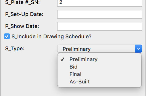
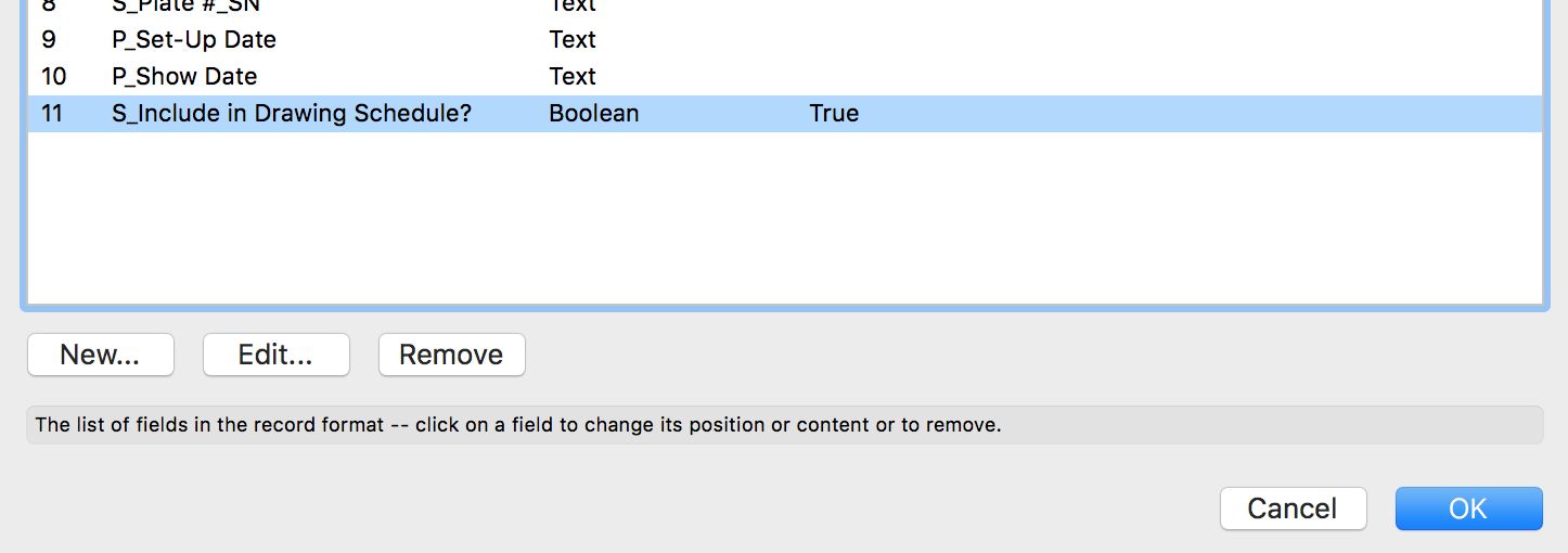
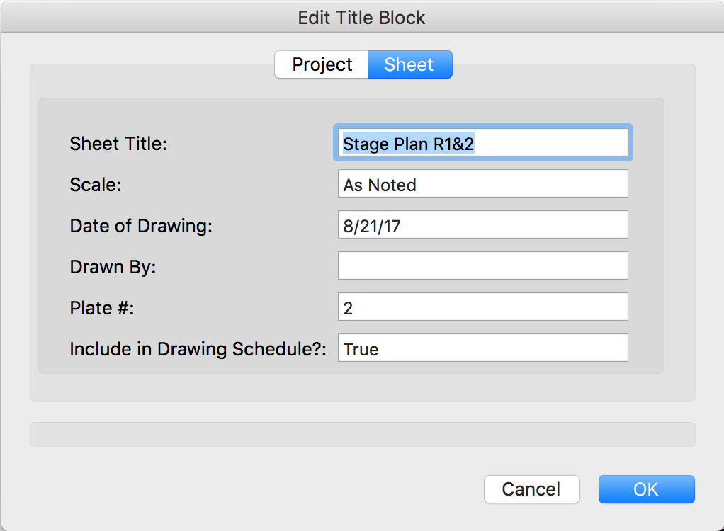
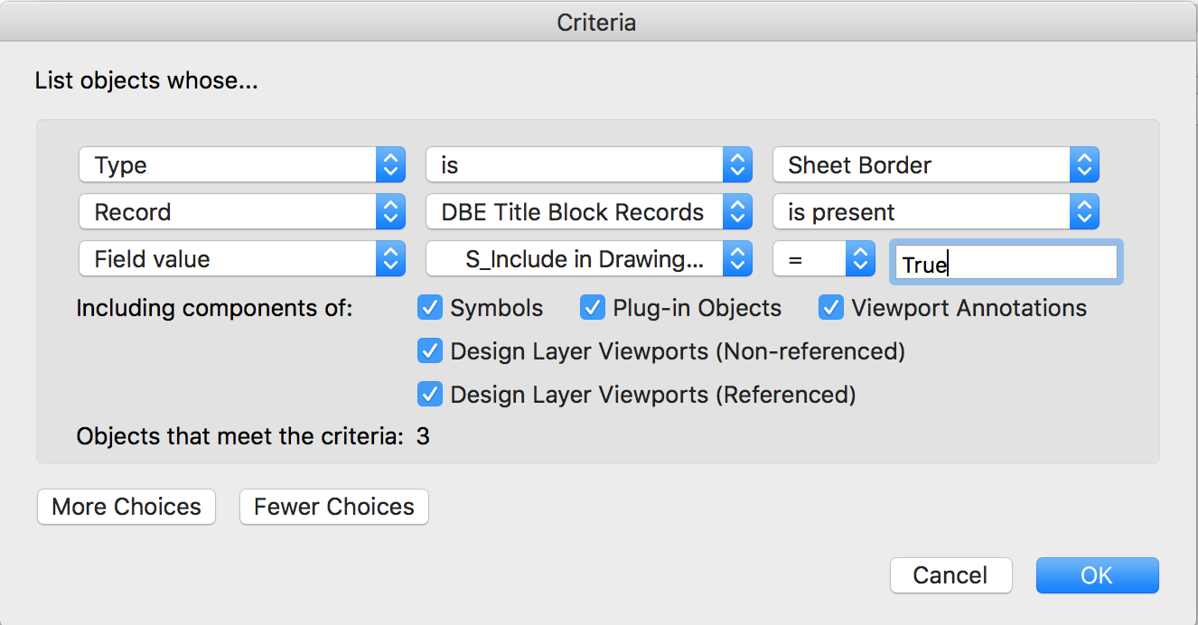
By the way, if you have multiple sheet sets and want separate lists (assuming they're using the same titleblock), you could have this field determine which list a sheet should be included in rather than boolean yes or no. Related to that, I wish that titleblocks would support the Record Field "Pop-up" option so that when editing a titleblock you could choose from a pre-determined list like you now can in the Data pane. It should also support Boolean checkboxes rather than having to type True or False. (Data pane) Please upvote this topic (hopefully this is already being implemented in 2018??):
-
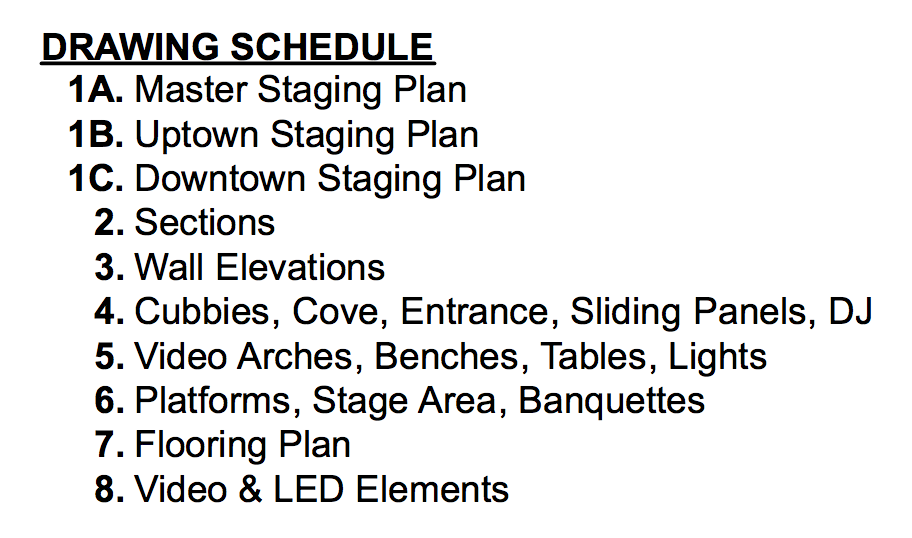
One approach that would allow you to utilize a Worksheet-based drawing schedule (sheet list / whatever) is to have a boolean record field named "Include in Drawing Schedule?" where you can say yes or no for each titleblock: This field would only appear in the pop-up when you double click your title-block; it's not actually linked to any text objects like other fields are. The Worksheet criteria would then be set up to only include sheets that have this field set to True, thereby ignoring sheets set to False or that don't even have a titleblock: Here's what a recent worksheet-based drawing schedule of mine looks like: I really like that I don't ever have to worry about manually updating it, especially since the projects I'm working tend to change drastically by the minute. Having the titleblock sheet number, sheet name, the Navigation palette numbers/names, and the drawing schedule worksheet automatically cross-update is vital to keeping our files organized and cohesive.
-
I just opened up that file, and indeed, OpenGL seems to now be broken. Sadness. Should probably be filed as a bug.
-
Improvements to Font Mapping
Andy Broomell replied to rDesign's question in Wishlist - Feature and Content Requests
I didn't realize this. I don't like that... So how do I know which Arial text blocks are 'font-mapped' from a different font, versus the ones that I've newly created which are actually just Arial? (Presumably there is no way, currently). Today I'm taking over a file from someone else who used some random handwritten font which I don't have on my computer. Is there no way to ensure that all text remains as Arial from now on (just as it appears on my computer) no matter who eventually gets the file? I don't want any text to remain associated with the old handwritten font since it's fairly hard to read (I have PDFs of the old drafting so I can see what it looked like before the current font mapping). Another question. If I select a text object which I know is being mapped, and manually choose "Arial" from the list of fonts, is it now Arial? or will it still map back to the handwritten font if it were available? -
Create Object From Shapes: Stage Plug
Andy Broomell posted a question in Wishlist - Feature and Content Requests
It would be great if the new Stage Plug tool were added to the list of options in the Create Objects from Shapes command. -
I knew it was a simple answer! Thank you