

Elite Exhibits
-
Posts
583 -
Joined
-
Last visited
Content Type
Profiles
Forums
Events
Articles
Marionette
Store
Everything posted by Elite Exhibits
-
Modeling 3D object - Material/textures and 2D color
Elite Exhibits replied to Cristiano Alves's topic in General Discussion
My 2¢ We use thousands of Hybrid (2D/3D) Symbols in our work flow The Top/Plan view looks finished, without the need to Render. Hybrid Symbols are a key to the success of VectorWorks. The 2D Component (Screen Plan or Top/Plan Component)is simple for ease of informing & editing, while the 3D can be complex and textured for excellent rendered visuals. 2D information (Text or an Image for example...) can be a part of the Hybrid Symbol and it automatically disappears when switching from Top/Plan to a 3D view. An alternate way to make 3D components is to use VectorWorks Tools/Menu Items for other than what they appear to be for. The attached example shows an extruded square, a Pillar and a Floor that all look the same ie: a cube. These items (...Pillar, Floor, Wall etcetera) all have an automatic component that is visible in the Top/Plan view and one is able to color them from the Attributes Palette. Use the Saved Views in the attached file to see a description - Both files are the same- exported to VectorWorks 2018 incase you are NOT running VectorWorks 2023 Peter Same Shape in 3D v2023.vwx Same Shape in 3D v2018.vwx -
@Jesse Cogswell DoMenuTextByName('Standard Views',2); {sets view to top} Adding this at the beginning of the Script above, edits a 3D Only Symbol in 3D - if not, then you see nothing, as VW assumes (When the drawing is in Top/Plan ...) that the symbol edit is 2D, or the 2D component of a Hybrid Question: DoMenuTextByName('Standard Views',?); does not appear to have a number that sets the drawing to Top/Plan view first - assume it to be Zero... (See attached) ¿ An alternate to DoMenuTextByName for this is ? Peter Standard Views VectorScript_1.pdf
-
Peter Thanks again to @Peter Neufeld. - I did find the information on the Context Menu>Align in the HELP (FYI - Where it is placed is ... Between Select Command & Dialog Box Opens ...might make one initially think it is part of the standard Modify>Align menu vs the Context Menu + that hidden Flyout / greater than symbol ...) ...as one who has decades of pressing Command Equals (⌘=) in Vectorworks, the keyboard shortcut is first, with the Context Menu a secondary solution. This is especially true as I have many Object Menu commands (Including the standard Modify>Align menu ...) in the Document Context Menu. This allows for faster (ie:safer...) Touch Free operation. Question: As there are Context Menu items that do NOT show up in the Workspace Editor, and they may require very specific circumstances to "discover" ... ¿ Is there a specific list of these program set Context Menu some where ? ...akin to the Vectorworks keyboard shortcuts PDF ? I am able to find them spread out within the Comparison of commands and tools...PDF (Link to the 2020 version - https://app-help.vectorworks.net/2020/eng/Commands_Tools2020.pdf), though this does not necessarily facilitate / indicate their use / location in the Vectorwoks application. As always, any applicable answers and appropriate advice are aptly appreciated. Peter Align:Distribute in HELP 2023.pdf
-
Thanks again to @twk & @Jesse Cogswell Almost... a great addition to our workflow - One script from @Jesse Cogswellworks to get to the Symbol Edit The reverse from @twk takes us back to where we were ... to easy One addition would be Decrease zoom by a factor of 2 Unable to find what works with DoMenuTextByName Assume I should find it in https://developer.vectorworks.net/index.php/VS:Function_Reference ¿ or ... It is NOT a menu item ? ********************************************************* PROCEDURE OpenEditContainer; {* Opens selected object's edit container based on current view Developed by: Jesse Cogswell Date: 3/23/2023 Revisions: *} CONST kEdit = 9743; kSymbol = 15; kTopPlan = 6; VAR h:HANDLE; symDef:STRING; BEGIN h:=FSActLayer; IF(GetTypeN(h)=kSymbol) THEN BEGIN symDef:=GetSymName(h); IF(GetProjection(ActLayer)=6) THEN SetObjectVariableInt(GetObject(symDef),kEdit,0) ELSE SetObjectVariableInt(GetObject(symDef),kEdit,7); END ELSE SetObjectVariableInt(h,kEdit,7); DoMenuTextByName('Select All',0); {select all} DoMenuTextByName('Fit To Objects',0); {Zoom - Fit To Objects} DoMenuTextByName('Decrease zoom by a factor of 2',0); {Zoom Out Cmd+2} END; Run(OpenEditContainer); ********************************************************* As always, any applicable advice and answers are aptly appreciated. Peter
-
Thanks Except- see attached, right click when editing a 3D Only Symbol ? Edit 3D Symbol.pdf Peter
-
Peter Interesting ... Have long used the Locus or locked object trick to force items to a specific location. Example: The Top and Bottom of a horizontal locked line are the same. Thanks Peter
-
Peter @Peter Neufeld. I am not seeing this I am assuming that you have a Symbol, it is 3D Only - you select it - select edit ( ⌘-[ ) - Then right click outside the object ? (Switched Workspaces to check an unaltered Contextual menu - also tested a 2D Symbol and a Hybrid) Peter
-
@Peter Neufeld. Question: ¿ Where in the HELP does it explains the different results when the Menus - Align/Distribute Objects is used vs the Contextual Align/Distribute >? (Assuming that there should be no difference... ?) I am getting different results between the two. Including some strange results with the Contextual Align/Distribute > It also appears that the Contextual Align/Distribute > is not directly available in the Workspace Editor ? As always, any advice and answers are aptly appreciated. Peter 1770549319_AlignContextual_1.mov
-
Question What to add to - Align/Distribute 3D - simple DoMenuTextByName script ? ...to get the dialog box to preselect the Z and Minimum ? (See attached) Peter PROCEDURE DoMenuTextByNameExample; BEGIN DoMenuTextByName('Align/Distribute 3D',0); {Align/Distribite 3D} END; RUN(DoMenuTextByNameExample); 3D Object Align and Distribute Dialog Box_1.pdf
-
Set Win VW shortcuts to behave like Mac VW shortcuts
Elite Exhibits replied to Rob87's question in Troubleshooting
SharpKeys -
Generic Solid or Solid Addition?
Elite Exhibits replied to Haydenovative's topic in General Discussion
Pat As always - ! Fantastic ... ! Peter -
Generic Solid or Solid Addition?
Elite Exhibits replied to Haydenovative's topic in General Discussion
Question for @JustinVH based on the above comment ... When we know we will edit specific items, like Extrudes and Sweeps etcetera we leave them as is. ¿ We also assume that these are SOLIDS ? Also ...Wall, Slab, Cone, Cylinder etcetera - all are SOLIDS The option to Convert to Generic Solid is in the Modify > Convert menu ¿ Is there a Convert to Solid option ? In our experience, the OIP does NOT show any Vectorworks created 3D item as a SOLID. Push/Pull a Layer Plane Rectangle, and the OIP indicates that it is an Extrude. Push/Pull this extrude and it is a Solid Subtraction or a Solid Addition in the OIP. Deform this Solid Subtraction /Solid Addition and the OIP states Generic Solid. Imported items (STL/IGES/DWG) may show as Solid, or Mesh, or Generic Solid. Question ¿ What distinguishes a SOLID in VectorWorks ? (Vs a Generic Solid) -
A smarter Smart Option Display
Elite Exhibits replied to WhoCanDo's question in Wishlist - Feature and Content Requests
This comment, by hollister design Studio, is in the above thread ... I never use 'views' because the number keys are too convenient - but could see this being helpful on a macbook... (Except the thread starts as Smart Options Display , then wanders across the galaxy a bit ) So. posting this question here: A smarter Smart Option Display Would like to create a Standard Views Set for the Smart Options Display that only has a few of the "Standard Views" - in logical order. Working on a laptop, sans Full Size keyboard, it would supplant the Standard Views Keypad Options with the Smart Options Display Able to create several Tool Sets and link to the Smart Options Display quadrants, Unable to Make or Duplicate and Edit the Standard Views. (...are Standard Views are Menu Items ?) - see attached As always, any appropriate assistance, Smart Options Display Edit Standard Views.pdfanswers, and advice are aptly appreciated Peter -
kitkaye More fun stuff - Script from Pat (?) - inside the attached VW 2020 file - Also ... short animation shows that a fundamental shape, inside an extrude (container) rotates when you attempt to edit it. (While the adjacent extrude does not. Run the script, with the offending extrusion selected - Indicate Zero/Zero with a click & the direction. Now the fundamental shape, inside an extrude, remains in location as expected. One Andy B trick: Make it a symbol at Zero-Zero (to begin with) then edit from the Resource Manager, never from the drawing. Let us know it works Peter 186984950_NoMoreRotationwhenediting.mov Container Script 2020_1.vwx
-
kitkaye When editing container objects, I like it when all the other objects disappear - at times, thought, one needs to see whats going on around - Check the VectorWorks Preferences and check the box - see attached Peter Show other objects.pdf
-
Was again digging for what I would tend to call GRAVITY and stumbled into this request. I am assuming that there is NO solution to this that works over all, especially if you are working in a perspective view? • For a 2D object, the Screen Plane / Layer Plane / Working Plane selection in the OIP is an odd, yet functional solution. • A fundamental 3D shape, (Extrude for example) also has a Z in the OIP - set it to Zero - easy solution, accept ... Rotate a fundamental item and you are out of luck with the OIP. • A symbol also has a Z in the OIP, unless it was created at other than Z = Zero for the active drawing. As In am finding that Symbols, imported from other designs / versions, are often listed in the OIP at Z = Zero, while the bottom of the symbol is NOT actually @ Z = Zero ... so a universal (¿ Script ?) solution of Bottom most point of the Selected Object is now Z = Zero would be great • I have taken to creating a Floor Object that is an extrude of Zero in the Z direction, centered at Zero-Zero. Snapping to the Center of this Floor Object appears to work in many situations (Rendered Open GL Perspective) - Or locate & Lock a 3D Locus at Zero-Zero - This method still requires the object, now with the Bottom most point @ Zero, Zero, Zero to be moved in the X & Y back to where it was. (...maybe you will get the 3D Locus to also be a Master Snap Point) The Working Plane example from Jonathan Pickup is good, just not a one step process. (ie: the way Z = Zero can be set for some objects in the OIP). I like the Jonathan Pickup video approach (See above) as it also shows the failings & short comings of the process. Like wise, changing to the Front / Ortho View and utilizing the Snaps, or Align, or ... This all works, just not as Asemblance originally requested above ...within an awkward 3D view. As always, any advice and answers are aptly appreciated. Peter
-
Cricket Lane Mat Modelling - Best approach
Elite Exhibits replied to Michael Siggers's topic in General Discussion
Michael Good job ! - In your VWX file attached above, it utilizes one of the interesting, yet confusing items in VW/RW 2D objects that are 3D objects. A "2D" Layer Plane object (3D Plane Object) is able to be positioned in 3D space and have an Image applied to it. Like wise, the bitmap itself, is able to be imported and positioned into 3D space. Both will retain their look without Rendering. Peter -
Cricket Lane Mat Modelling - Best approach
Elite Exhibits replied to Michael Siggers's topic in General Discussion
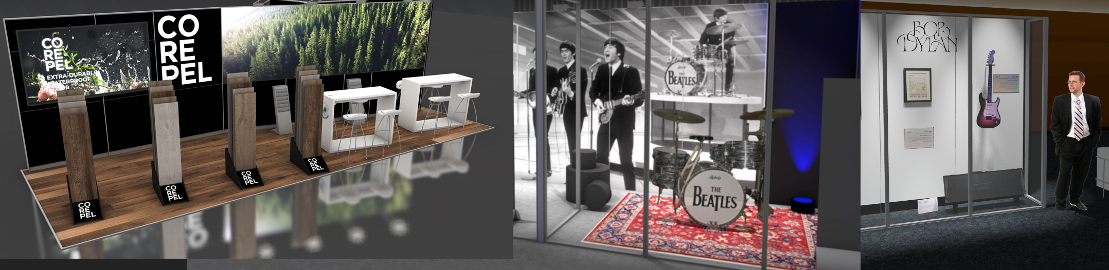
Michael Siggers My take You need bitmap files of the brown & green in your design (Grass n Soil) (I used a quick n dirty screen shot of your attached render...) Create a 2D Lane - all out of simple 2D rectangles Green Outside Strips, Brown inside strips - 2.4Mx25M overall in the attached Add the three central light stripes, also as rectangles - (You can add the cross lines as you are aware of where they reside ...) I like to color the rectangles to match (as close as possible) the Image color to be used. Helps to identify. In the Resource Manager, Import the Green and Brown bitmap files noted above as Images. Select the desired rectangle and apply the Image from the Attributes Palette Bigger basic bitmap file = less evident the tiling will be. For the three center stripes, I simply selected a color that looked apropos. Select all and Group. In the Object Info Palette, make sure that this group is at (Zero - Zero) (...avoid VW container edit aggravation later on.) In Top/Plan view You should now have a full color 2D Lane. Select a section and take a screen shot. This will be the texture for the 3D portion. (Longer is better) You may need to edit this in a pixel editor. On top of this 2D Lane draw a new 2D rectangle. In the attached example, I created a 2D rectangle directly on top of the above 2D Lane One could also double click the rectangle tool, enter dimensions (2.4Mx25M) and position at (Zero - Zero) Extrude this rectangle, and set the value to 9mm (The desired lane thickness) In the attached example, there is a duplicate (2.4Mx25M) extrude. One is simply colored green in the Attributes Palette, the other is textured. Green Extrude is 9mm thick, and the Lane Texture is applied to an Extrude that is zero mm thick The Z of the Green Extrude is -10mm In the current Version of VW/RW (2023) you should be able to apply the forth coming texture to only the top surface. So far I find this feature perfect in the training videos, and awkward in reality. In the Resource Manager, create a texture with the screen shot taken from the 2D Lane in Top/Plan view Set the Texture Dimension to match the lane width (2.4M) Select the desired extrude and apply the Texture from the Resource Manager. Render to test check orientation. Adjust rotation in the Object Info Palette - Render Tab. (¿ Should be Zero or 90° ?) If it is hard to select the specific Extrude to texture, from the 2D Lane , Group the Extrude and Edit Group, this will isolate the object. Even more so if the Show Others Option is unchecked in the Display Tab of the Vectorworks Preferences. In the Top/Plan View, select all the items. Create a Symbol from this combination of 2D and 3D (Modify Menu) Should be a Hybrid Symbol that looks finished in the Top/Plan and also in a Rendered State See Attached Peter Cricket.vwx -
Rishie What I have experienced, this was with a corporate clients and their own custom font(s), we needed to delete any existing fonts and load the fonts from the same source onto all the applicable machines. Then the text played well in the sandbox. Question: Is part of your screen shot above (the Logo...) from a separate file, or is it from a font initially assembled / created in something other than VW ? Peter
-
Curious re: Other than PUBLISH - ¿ what else utilizes the Saved Set Manager Dialog Box ? VW Help: "Many Vectorworks dialog boxes allow you to save the current settings so that they can be quickly applied again." Advice and answers are always appreciated ! Peter
-
FYI I have had things disappear and cause issues - Happens when I place Palettes on other than the main screen. - See attached - In this case the keyboard appeared to be malfunctioning as the Resource Manager would not open pressing the Command-R combination. ¿ I assume that it is based on the video output in the laptop ? Peter 827803353_ResourceManagerLost_1.pdf
-
Unable to render Symbol while Editing from the RM with a Sheet Layer active... Question: Assume that this is the norm, not a bug or a "feature" a Sheet Layer is active Viewport rendering does not look 100% correct One Symbol is not textured correctly Edit Symbol from the Resource Manager Able to "edit", just NOT able to test render (Greyed out) and see the results Change to Design Layer Edit Symbol from the Resource Manager Able to "edit", and able to render. Moral of the fable - switch to the Design Layer to Edit, even from the RM Advice and answers are always appreciated Peter 1189523084_UnabletoRenderSymbolEdit.mov
-
resource library items not showing
Elite Exhibits replied to boxboydesigns's question in Troubleshooting
BoxBoy I tend to do this in reverse - as there are Place Holders (VWplaceholder.txt) in some Library Locations, I tend to find a real drawing first in the Finder, then open it - As Pat pointed out - There may be no items visible in the drawing, this Marshall Stack is an exception (Speakers Miscellaneous.vwx) - and the Resources are only evident when viewed in the Resource Manager - There are some that I have opened, then wonder (as you point out...) what should I see. At the top of the Resource Manager, select All Resources from the Drop Down, and this should expose the contents within the drawing. ¿ It would be interesting if one of everything was in the drawing, with named saved views ? Peter Resources.mov Drop Down.pdf -
Designated spaces for population at a later stage
Elite Exhibits replied to Jmoo's question in Troubleshooting
Jmoo Take a look at this Thread I have used the script to create and then update Textures, used a graphic panels on walls. Peter -
Can the same symbol be assigned to different classes?
Elite Exhibits replied to Sade16's question in Troubleshooting
Sade16 A common problem I see happens during the creation of the Symbol ¿ What class is it assigned to ? (See attached) Often this is missed in the process and may end up as a Class that is NOT active. Start by turning on ALL the classes and see what appears ... The Visibility Tool is a quick non destructive way to do this. Peter Visibility Tool.pdf Symbol is in What Class.pdf
