All Activity
- Today
-
 Great, please private message me - thank you!
 -
 Dave Holmes joined the community
 - Yesterday
-

Creating Partial Plant Schedules - How to Define Criteria?
Tien replied to Michal Zarzecki's topic in Site Design
Do you know how i CAN achieve this in detail ? -
Worksheet for planting for visible viewport on sheetlayer only.
Tien posted a question in Troubleshooting
Hi guys, i have been reading around ways to get the plant schedule to work properly to show/count only plants that are within the viewport - I tried different criteria combinations but they are not working for me. What I tried was : Did i miss anything or that's not what it should be ? P/s : I tried class set up way, location polygon way and layers way - they are just time-consuming since i have like 50 different viewports. I wanna try to get the schedule to work for me instead of other way around.

-
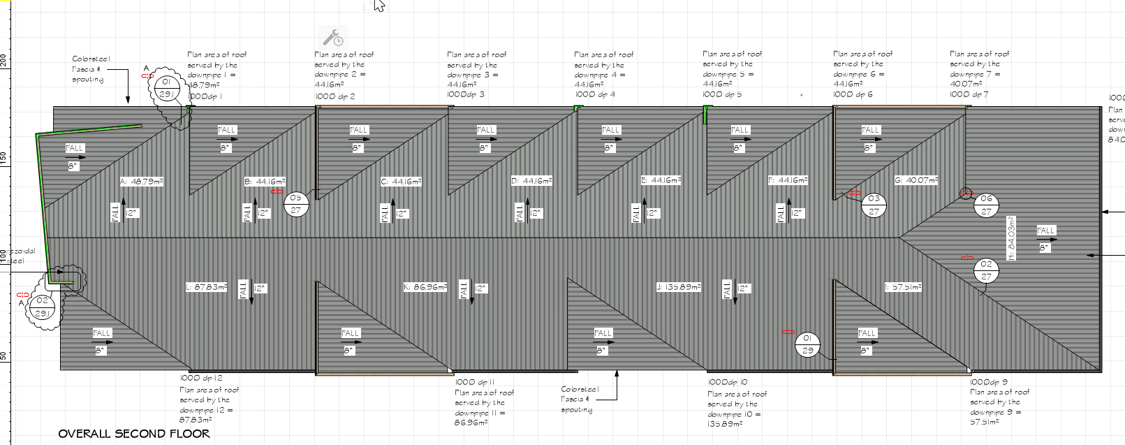
Thats an interesting approach, sounds like your roofs are quite complicated. Do you have screenshots/examples to share? Personally I use the roof face tool, and yes start off with the roof object. But when there are complicated junctions, thats when I resort to the roof face. We stick with the roof/roof face tool as they have components built in that feed into worksheets we use for coverage calcs etc.


-
 Michael Clarke joined the community
 -
Are you still looking for a 2019 version of Architect?
-
Most of our residential roofs are way too complicated to use the VW roof tools. I use to use a combination of the Create Roof tool and the Roof Face tool but ultimately I ended up creating my own library of roof faces out of solids, I have all my different pitches, with the different cuts for brick or siding, overhang, and also the soffit already drawn in. Once I set my wall heights I just grab my roof faces and set them on the top plate. I then just push pull all of my intersections and trim off the overlaps with a combination of the Stitch & Trim tool and the Split tool. This has been by far the easiest and fastest workflow we've found for complicated roofs. After I do my intersections and trim the excess, I join my faces together with the Add Solids tool to get a beautiful roof. The problem is when I have to make a change, once my entire roof is added together as a single solid I can't get it broke back apart. Ungrouping, editing solid, or editing features does crazy stuff. It'll throw random solids out in random spots but will not break the solid apart. I can use the Split tool sometimes to break a section apart but this only works about 1/2 the time and will leave solids that aren't even touching act like they're added together. Once the solid addition is too complicated, I'm assuming, the Push/Pull tool also stops working. If anybody understands how solid additions work better than I do to where I can understand the behaviour better to figure out a way around these issues I would greatly appreciate it. Also, I would like to hear any other workflows, tips, or tricks from any of you who also draw complicated roofs.
-
 Dannyboi joined the community
 -
@E|FA Yes, you could be right that VW is crashing during Quit which means it is not saving the palette positions. Using the manual save might be the solution to this one. But if that does not fix it then my suggestions should be the next in line.
-
Wishlist item
-
This sounds like corruption in the preferences file.
-
Thanks Mark, this was exactly the issue I was facing. In doing some further digging I just realized I was watching your amazing webinar on Schematic Views. Really incredible stuff and the capabilities Vectorworks has for lighting design is immense. I wanted to ask a general follow-up question and in some way I'm sure it relates to the aforementioned webinar. Some of what you went over is still a little confusing to me, not because of a lack of clarity on your end, only because it's just a lot of information. I've drafted a lighting plot using primarily hanging positions but a few simple lighting pipes as well. In creating a top/plan view in a viewport, it looks great. My hanging positions, lighting pipes and lighting device symbols show up as desired in a wireframe rendering. In an ideal world, I'd like to use the same model to create a side view in on a second sheet. In doing so, everything shows up as 3D models. Not unexpected, this is what how it's worked for every other thing I've modeled and plotted. In recognizing this eventuality, I ended up coming across your webinar for Schematic Views. It seems like eventually, I would want to figure it all out and be able to use one master 3D model/LX Plot to create every viewport I need. In the meantime, is there a "shortcut" or a few direct steps I could take to use what I have as a side view in a viewport and preserve the depictions of lighting devices, lighting pipes, etc that I see in a top/plan view? Without totally figuring out the Schematic Views, my temporary solution might be to draft a secondary "side" view of my model on another layer in top/plan. Essentially as if you would sketch two separate plots on paper. Perhaps this is the way it would be done without using Schematic Views? I'll eventually get around to figuring out everything in your Webinar. For now I kinda need a simpler solution, even if it's redrafting a second "side" view.
-
This might seem small - but VW24 does not seem to save the tool pallet sizes between opens. I am forced to resize all my pallets at the start of every session. There is got to be a way for them to have a save state. This is such a clunky and disheartening way to start my Vectorworks day.
-

AI Visualizations-Thougthful discussions
VIRTUALENVIRONS replied to Luis M Ruiz's topic in AI Visualizer
My sentiments exactly for the real thing, but for the abstract the Visualizer is compelling. It does appear that the Visualizer is aimed at the Artistic world.. Good to know you are a C4D person. It is a great combination. What is your particular area of work or interest? -
I think you need to expand on what you are trying to do if you want to get suggestions.
-

Show 3D axis labels - layer plane vs working plane
Oaktown replied to Oaktown's question in Troubleshooting
@Josh Loy I agree that having both being displayed would be confusing. From my perspective, I would prefer to have XYZ when working in the layer plane and X'Y'Z' when working with a different working plane. Thank you, Frédéric "Oaktown" -
OK, I spent a little more time but I have some real work to get done. Here are just a couple more images of the Typhoon, I probably generated 50 - 60 to try and get something I could pass off as a rendering. I don't think I even got close. the AI is just not seeing the detail in the reference images and accurately conveying that to the generated images. I am sure I could get better results with a few hours of work, but why not just do it right in C4D??


-
 Hello, I am interested. Thank you. Ďurišová
 -
 Aha ok thank you. That formula was actually taken from Luka’s data mapping example earlier. I just transposed it to a Data Tag to make the point that one wasn’t gaining anything by using the Data Manager in that case. It’s not a tag I use myself!
 -
VW Landmark 2024 UK perpetual license for sale.
G.Arch replied to ArturK's topic in Buying and Selling Vectorworks Licenses
Hello, I am interested. Thank you. Ďurišová -
G.Arch joined the community
-
VW Landmark 2024 UK perpetual license for sale.
G.Arch replied to ArturK's topic in Buying and Selling Vectorworks Licenses
Hello, I am interested. Thank you. Ďurišová -
 @Tom W. Not under the values used for WS_IF. In other words if your tag callout structure is #objectdata(reference)#@WS_IF or WS_IFS:ELSE --- > document dimensions, or custom dimensions (like inches, or decimal feet) are inherited from the component or whatever the dimensional reference is. However If your tag structure is something like you mentioned : #WS_IF((COMPONENTTHICKNESS(1)=0), ' ', CONCAT(COMPONENTNAME(1), ' ', COMPONENTTHICKNESS(1), 'mm'))# The value that would be generated from that statement would be a numeric value (not a dimensional one) - which is why you add 'mm' to it. It would fine in the metric system. In imperial, when you have fractions of an inch - they're not divisible by 10, and converting them back to fractional inches would be a nightmare. The best thing that can be done is to generate the value into inches by dividing the value by 12 (since the default document units are feet - not inches). Just FYI and its relevance is that when you provide documentation in America, fractional inches are much easier to understand than decimal feet. I have found a work around to this situation already using the 1st condition above when you have multiple variables in a conditional statement and need to preserve dimensions.
 -
Thank you. The problem also happens when you make Roof Faces. (Rectangles seem to be the culprit).
-
-
Has anyone tried excel referencing to replace symbols in Vector works drawing?
-

Show 3D axis labels - layer plane vs working plane
Josh Loy replied to Oaktown's question in Troubleshooting
@Oaktown Thanks for pointing this out and after looking, it does seem like bug. Went back a "few" versions and found where it was working as shown in the screen shot. Looks like we used to draw both, but I'm not convinced that's the best approach. If I understand your original comment you think we should draw X,Y,Z when the Working Plane and Layer Plane are coincident, and just draw X', Y', Z' when they're not. I'll put a bug in for this and appreciate your feedback!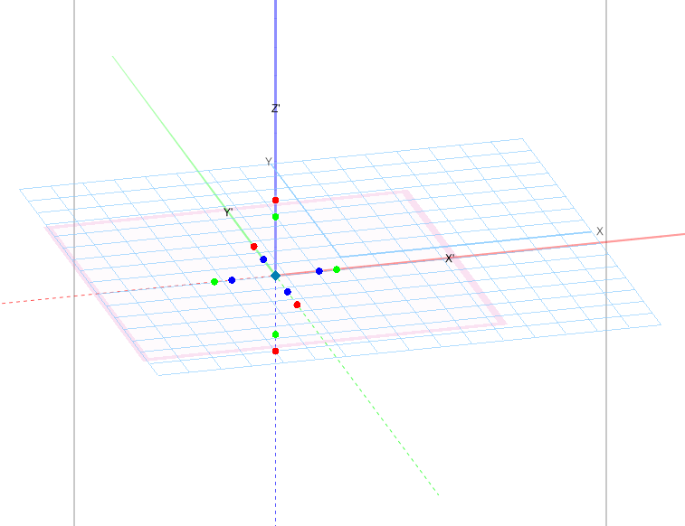
-
 Vectorworks Designer 2023 Perpetual License For Sale. Buyer can choose to download either the MAC or PC version. Best offer/$2,500 US.