Search the Community
Showing results for tags 'bim'.
-
 Hi All, after much pain and suffering trying to find out how to do it I thought I would share how I align my VWs models with lead consultant's (Architect's) Revit model. This assumes the following: You are not lead consultant so you haven't created the shared project coordinates yourself. You are not lead consultant so you are contractually obliged by your client to align your model with the lead not the other way round You are not the BIM coordinator and have received a useless Revit centric BEP. You understand the difference between User Origin and Internal Origin in VW. You understand the importance of modelling close to the Internal Origin to avoid glitches You are doing this before you start modelling. While the steps are the same for after you've modelled, changing the Internal Origin is not advised unless you are being held at gun point by the client. All your sheet layer viewports will be messed up and need reworking. Key message: you need to change the coordinate of your Internal Origin to match the Internal Origin of Revit (which should also be the shared project coordinate). Forget User Origin for now. Steps: 1. Ask the lead consultant (or whoever has set the shared project coordinates) for the Northing and Easting coordinate (relative to British National Grid or your local system) for the Revit Internal Origin. Revit does not recognise your VW User Origin so changing the User Origin won't help align models. 2. Firstly make sure your Vectorworks Document is set to your local coordinate system: File> Document Settings>Georeferencing>tick 'adjust origin and orientation of georeferenced data to match document coordinates' (not sure if necessary). in this window check 'Use an EPSG code or CRS name' Click Lookup and find EPSG 27700 / CRS name: OSB 1936 / British National Grid (or your local system). I had to Google this. Close Document Georeferencing window. This makes sure you are in the correct overall system for Northing and Easting coords (if in the UK). 3. If you now go to your Geolocate tools and select 'Geolocate' while looking near your Internal Origin VW will download and display a satellite image of the world at your Internal Origin. For me this was default right next to the Greenwich Observatory in London. You want your project site to appear here instead in exactly the right location to the mm so... 4. De-select the Geolocate tool (this step was just to demonstrate the location of your Internal Origin in VW relative to the real world). 5. Draw a circle anywhere and type into its centre point properties the Northing and Easting of the Revit Internal Origin. 6. Select the Geolocate tool again and click on the centre of the circle. You get a warning that this changes the Internal Origin of VW but accept it anyway. 7. Now your Internal Origin is the same as the Revit Internal Origin and should be in the 'real' site location. Assuming the Revit user knows what they are doing. 8. Select the Geolocate tool again and hover over the Internal Origin - it should download the satellite image of the real location which should be your site. This step is just to check everything has worked and is not necessary. 9. Head to Tools>Origin>User Origin> check 'Set User Origin to Match the Georeferencing coordinate system'. This just makes sure your User Origin is reset and providing you real coordinates if you have been moving it in the past. 10. Celebrate. 11. if the Revit using lead consultant has also rotated their Internal Origin I am pretty sure you can do so too by heading back into File> Document Settings>Georeferencing and changing the angle to true north here. Edit: the Geolocate tool has a setting option to rotate the Internal Origin. I don't know if it is possible to also change the Z height of the VW Internal Origin but it is less important. Revit seems to struggle with moving IFC models into position manually in the X Y plane but moving it in the Z axis is a relatively simple task and the Revit using lead consultant shouldn't break a sweat over it. I only share my model as IFCs to Revit as you get control over what to export. It is important to make sure your User Origin is set to Northing and Easting 0,0. This ensures you get proper coordinates from your model and you import references in the correct position but also for file sharing across multiple softwares. While Revit only recognises Internal Origin, Autocad and Navisworks seem to use your User Origin when importing. Hope that saves some of you your sanity. Jack
 -

AI command interface for Vectorworks
Christiaan posted a question in Wishlist - Feature and Content Requests
AI rendering is an obvious feature to add to Vectorworks, but what about adding AI to the interface to assist with modelling? e.g. prompt: change plasterboard thickness of all Wall Styles in file to 15 mm -
Hello everyone, i hope you are doing well. when i try to export the model in IFC 4, it exports all geometries that is made by hardscape tool (Belag/Weg tool in the german Version) all in white, with no material or color (see the pictures in the attachement for better understanding of what i mean) only simple objects or pre-made symbols do have colors. is there a reason for that? how can i export the wanted colors/textures with the IFC model? thanks in advance.


-
Is it possible to schedule items (symbols, windows, doors, smaller spaces) by what space they are within the boundary or touching the boundary of? The more we get information in models that we want to schedule the more I realise this is the way I want to group them. Doors schedules - what spaces do they service. Bathrooms/Kitchen - modelled in 3D with each fixture a symbol - would love to schedule the fixtures by room. Apartment schedule - how big the balcony, bedroom, kitchen space associated with the apartment space. Yes realise I could have a layer per room but that when seems like double handling would be great if someone has found away to test what space the item is in. edit to note: this is post 777
-
Hi guys, Can anyone tell if the export ifc works with site model? I'm working with an office that uses revit and the site model object is becoming a problem. Export directly a RVT file, the site model becomes a generic volume, that hardly "translates" to a terrain object within revit. The export ifc isn't working, tried a lot of variations on its settings, but the file comes empty. Anyone can give a help? Thanks!!
-
Hello everyone, I hope you are well. i posted that already in Site Design forum, but i though maybe here it will have a better chance. I would like to ask if there is a way to map the geometric information of an object, such as length, width, height, volume, etc.... to the required IFC date field How can I assign this information? Is assigning to a customPset an efficient workflow? thanks in advance for your help
-
 Hello. We are diving deep in the use of data visualizations. But there are two main weakpoints/hurdles that make their use not-so-nice. 1. The option to completely hide objects. It was already posted here as wish. 2. The implementation of clean lists of referenced items. Let me elaborate. We strongly use referenced files, they have a coherent layer, material, assets, etc. structure as the host file BUT when we list the data-fields for data visualization, there are SEVERAL problems. a. Fields can not be searched for or even alphabetically ordered... with >100 Layers, the scrolling is painstaking. b. Fields are "doubled". We made the layer structure coherent, so we want the "Wall" layer to be overwritten for all the hosted files as well as for the host file... imagine we have 3 files + host and 100 layers... that is a nightmare... A super addition would be if we could list "only" a certain set of data-fields corresponding to a certain filter... similar to what is already possible in the layers and design-layer palettes... Thx in advance and UPVOTE if you like! 😍
 -
Following various advice on BIM best practice I've been setting up a project involving two buildings with a separate file for the site model and separate files for each of the two building models. All origins are synced across files (I'm using rotated view to work on the models) and I've managed to use Layer Import mode when referencing by having unique names for Design Layers + Story Names and Prefixes across the project. But workgroup referencing is bringing with it a whole host of trouble-shooting problems (and another [long] step in the file-save process). I find it very buggy. Which begs the question: why am I putting my building models (and sheets) in separate files? I would rather work in a single file for a host of reasons (including being easier for my colleagues to manage). Vectorworks can easily handle a project this size (two houses with 4 levels). And in terms of collaboration with other consultants, it doesn't matter that I have separate files or not does it? Convince me. @shorter?
- 15 replies
-
- 3
-

-
- bim
- workgroup referencing
- (and 1 more)
-
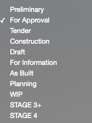
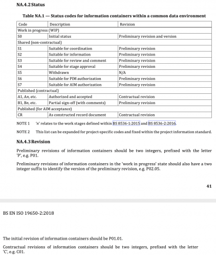
Below are two screenshots. One of some traditional drawing status notes of old. And next to it is ISO 19650 BIM status/suitability codes and descriptions (from the UK National Annex). I find some of the ISO suitability codes and processes a little confusing, particularly regarding work in progress. Any thoughts? Work in progress S0 - Initial Status - as I understand it this is only for internal use only, when editing your model/drawings, and should never appear on models/drawings shared with the rest of the design team. ISO 19650 explicitly states that information in the work in progress state/folder shouldn't be accessible to other task teams. But we often need to discuss work in progress with other team members so how are we meant to issue WIP information to other design team members if no one else has access to our work in progress folder? Should we instead be issuing in the Shared folder with S2 Suitable for Information, as below? If so then what revision code should be used? If it's work in progress then it's meant to have a revision code with a two-integer suffix (e.g. P01.01) but ISO 19650 UK Annex states (NA.4.3 Revision) that this kind of revision code is for work in the Work in Progress folder/state. Which no one else has access to.... Shared (non-contractual) S1 - Suitable for Co-ordination - I find it a little odd that the first status code is 'for co-ordination' when we would typically issue information 'for comment' or 'for approval' before we issue 'for co-ordination'. S2 - Suitable for Information - simple enough I guess, but no explanation in the ISO 19650 UK Annex defining it accurately. S3 - Suitable for Review and Comment - see comment above on S1 S4 - Suitable for Stage Approval - what is a "stage"? Can it mean any self-defined stage (e.g. "layout approval" stage). Or does it mean RIBA Work Stages? Or does it simply mean this is suitable for final approval before moving to a 'for construction' status? S6 - Suitable for PIM (project information model) Authorisation - straightforward, information that's ready to be authorised for management of the construction project S7 - Suitable for AIM (asset information model) Authorisation - straightforward, information that's ready to be authorised for asset management of the project Published (contractural) A1, etc - Authorised and accepted - straightforward, approved and accepted information for construction B1, etc - Partial sign-off (with comments) - straightforward, good way of revising 'for construction' information Published (for AIM acceptance) CR - As constructed record document - straightforward, 'as built'

-
Hi All, We need to align our landscape model with the architect's model and engineer's. Our model is aligned to true north - theirs to orthogonal on the x/y axis of the software. I can position our model in the correct location (very near Internal Origin) while retaining true Northing and Easting readouts by setting the User Origin where it needs to be relative to the Internal Origin. Problem arises where I need to rotate our model to align with theirs. User Origin coordinates do not rotate with the model obviously. Is there a way to not only move User Origin to maintain true project coordinates but also rotate User Origin to compensate for our model rotating to match theirs? Thanks Jack
-
I have a site model file and two building model files. Each building has the same Stories (BASEMENT, GROUND, FIRST, SECOND), but the Story Elevations for each building are different. Is it possible to use Layer Import mode when referencing multiple building files into the site file? If so, how do I deal with Stories and Levels? Do the Story Names and Prefix/Suffix need to be uniquely named for each building model? And then I need to add the Stories to the site model file. What about the Level Types? Or can I ignore Level Types in the site file, even turn them off? Or do I need to make sure they're all on and matching the model files?
-
Hello, Is it correct that you can only overwrite the outline of the wall component in section an floor plan but not in isometric views by class? So we have to set the class existing-wall- exterior to 0.10 and then overwrite the class in floorplan to something like 0.35 mm? And not the other way round (class with 0.35) and viewport class overwrite with 0.10 to get a fine line in an isometric view?
-
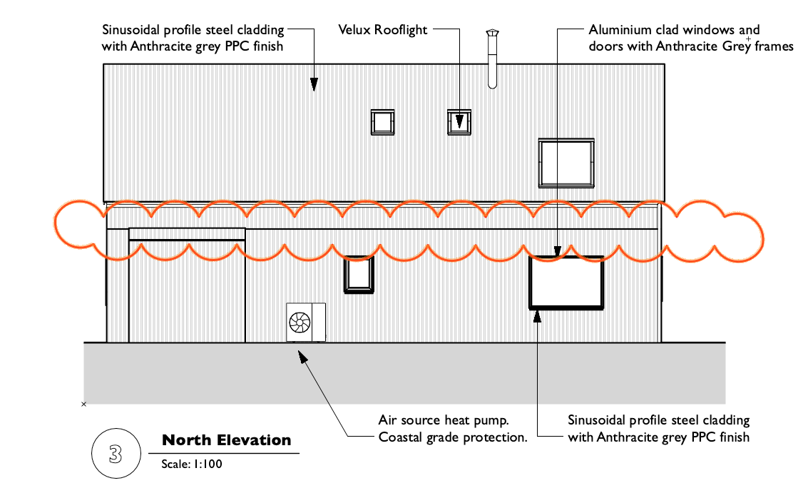
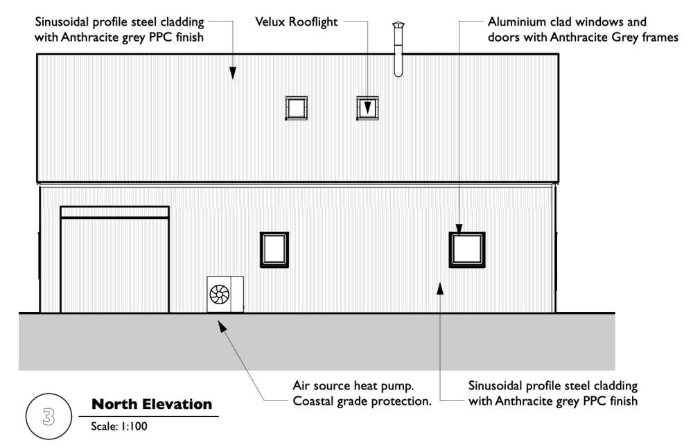
This is what the elevation is supposed to look like. Screenshotted form the PDF last time I issued the drawing. I opening this drawing again today made some minor changes to road in an unrelated part of the project and this is what it looks like now with thick black seam line incorrectly shown between the ground and first floor. I've spent all morning trying things like moving walls around and various other tricks to try and get it to recognise that it's the same material in the same plane and it hasn't worked. I would have been quicker redrawing these in 2D now. Stuff like this happens on every other project. I've seen this elevation merge materials fail bug so many times now and it always shows up half way through a project when everything has been working perfectly previously. So frustrating.

-
Hi Everyone! I´m trying to map the material description property of our material resources into the IFC Material field. The problem is that whatever I do, I only get the "Resource name" into the IFC Field. I know the expression I´m using "works" because I mapped the material description into the IFC Tag field and it got what I wanted, but I don't see why I can overwrite the Material field. Using the resuource name is a no-go, because it has our internal coding and this is not suitable for all the other project agents. Any help would be really appreciated.
-
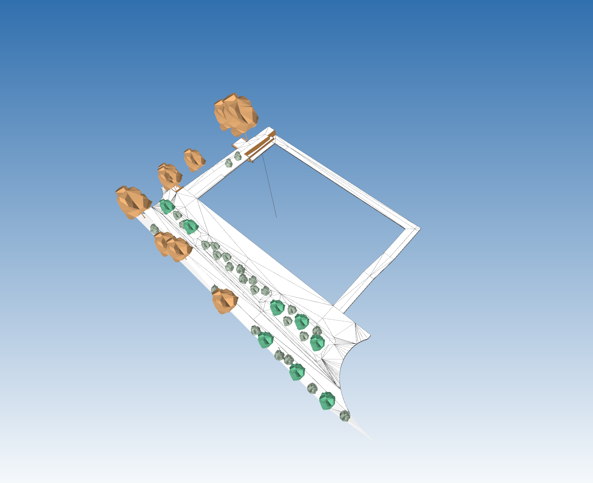
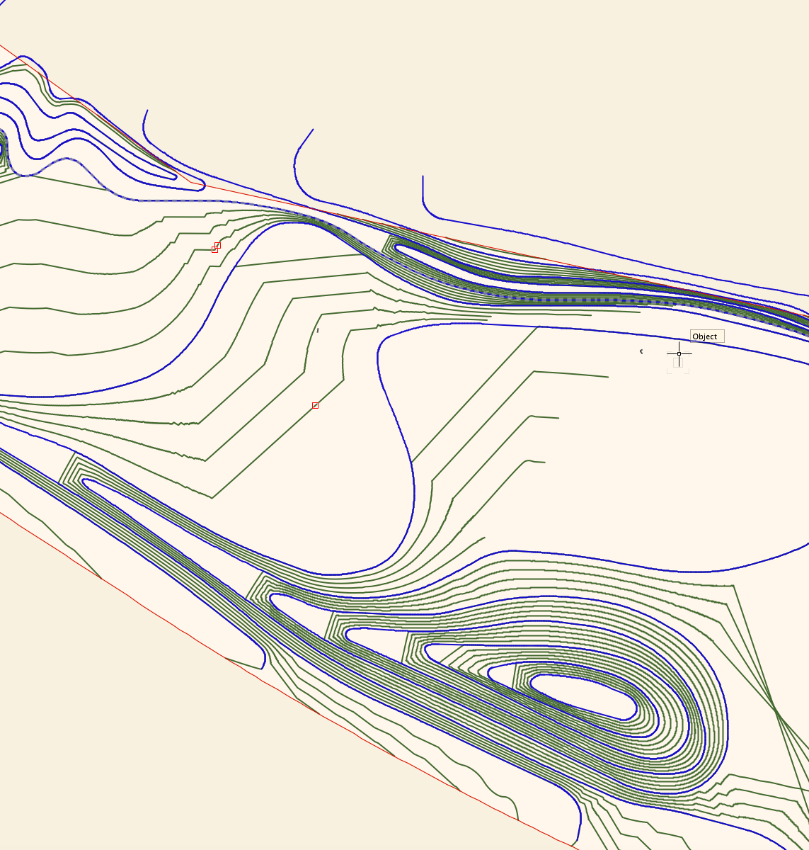
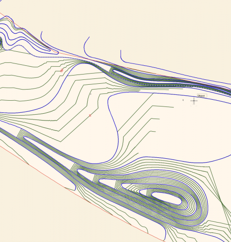
I'm wondering if I'm missing something in terms of the control we have over site modelling in Vectorworks. I've attached a screengrab of a site model I have created. Blue lines are the 3D polyline contours I have drawn and set to 0.5m height intervals, the green lines are the contour lines generated by the site model calculation by Vectorworks, using my blue lines as input data. I have two big issues with this output, namely: I want the model to EVENLY interpolate between the contour lines - for example on the hill to the bottom of the screen grab, I want the mounding to extend evenly to the left, I don't want flat platforms between each level. I want the contours to actually follow the curves I have drawn, and not truncate my contours in large angular lines!! (As seen in the middle of the screengrab.) Is there anything I can do, aside from draw contours at really tight intervals to reduce the visibility of the problem? Is this just how the site modelling algorithm works? I understand the need for a mathematical algorithm, but this results in a fundamentally incorrect site model I can't really use for anything in terms of BIM or production information, as it isn't giving me smooth grades. I'm sure I could fudge it for visualisation purposes, but I need an accurate technical model I can issue in IFC form to provide information for collaboration and also construction. I've turned on mesh smoothing in document properties, which makes the rendered model appear slightly less angular, and also turned on contour smoothing display, but I need an accurate model in terms of BIM compliance and I'm not sure I have this control outwith doing an excessive amount of contour drawing. Is Vectorworks the wrong software for this, or am I missing something? Any ideas or advice would be much appreciated. Lisa
-
Is there a way to "surely" import a VWX file into another?
arquitextonica posted a question in Troubleshooting
Hi All! I'm currently working with two files referenced inside a third. The design layer AND classes structure is coordinated between the three so that we can model and design at will. Thing is that we are using the option for the referenced viewports to use the "host" classes visibilities, but each referenced file is split into several viewports each placed on the corresponding design layer so that when we layout in the host file, we see what we want... Thing is that I'd like to "collapse" the two guest files into a single one, and "try" the project sharing way instead of the referencing and here comes my problem. When I "break" the reference and tell VW to import the file, the design layers are imported with a new-name instead of importing the objects inside the existing design layers (which would have been just logic for me)... So... is there a way in which I can "paste" together two different models of two different buildings that have the same design-layers, floors, reference levels, etc. and MAINTAIN all this very important information structures? Thanks all in advance!!! -
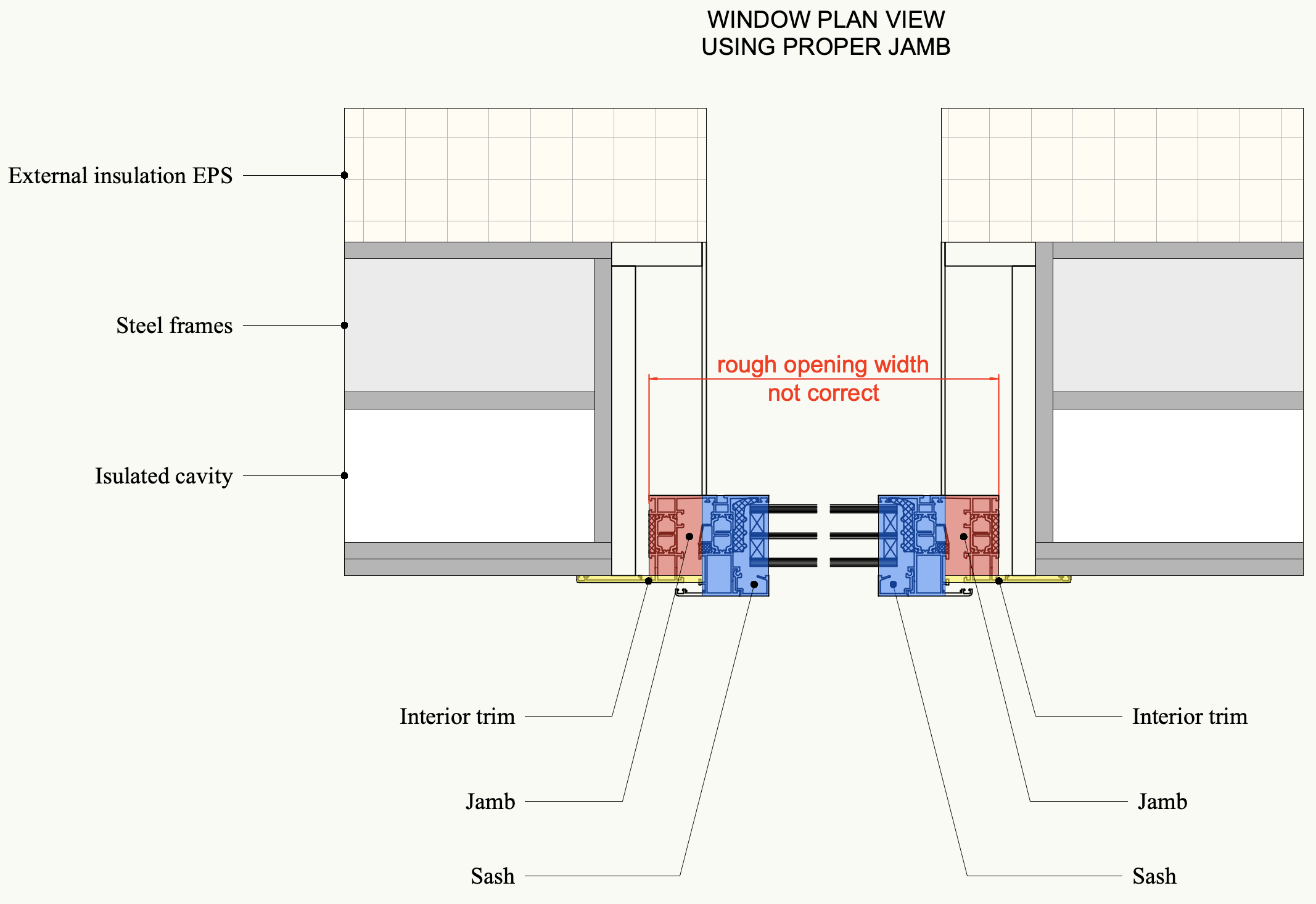
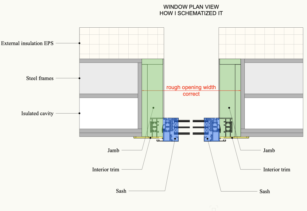
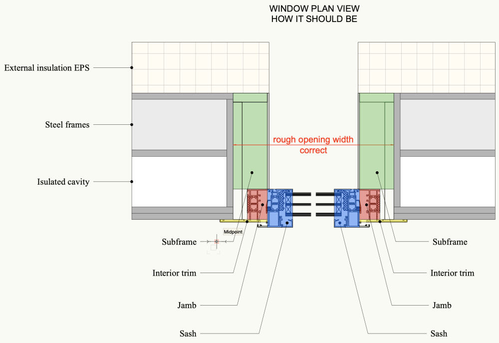
Hi everyone, I'm writing to try to understand how I should represent using the window tool the subframe (also called false frame) of an aluminium window. I would like to schematize the detail I received from the manufacturer using the window tool parts. I need to schematize the subframe to give the correct wall "hole" (rough opening) value to the building company that has to leave the right empty space in the framed structure to install the windows later. The wall structure is made of steel frames, similar to "light steel frame" by Knauf. Can anyone help me? I used the jamb to create the correct Rough Opening Width and the Rough Opening height (attached) but I know it's not the correct way to do it. Any ideas? thank you, Martina

-
Hallo All! I'm currently involved in a rather big project with several buildings that together make a block. We are thinking of splitting it into several files and federating them together in a master file, and I wonder if there is already a concrete workflow for this as, after my first attempts, I've hit some thick walls and I don't know if I'm doing something wrong. Let me explain... I make a file with all the correct storeys with the corresponding design layers attached to the correct reference heights. I open a new empty file with the same design layers and reference heights and reference the 1st file (is that right?). 1st problem is that the "reference object" is in the DL where I placed it and I can't control the reference visibility from the main file (yes from the object Layervisibility)... BUT I can configurate the reference so that it uses the same classes visibility as the host file. Is it possible to do something similar with the layers? My solution is to copy the reference in each design layer and adjust the reference layer visibility accordingly (i.e. copy the reference from GF to 1stF and turn off GF). This is painstaking! I get a "legoed" result. 2-3-4 references on top of each other... it "looks" right but it is horrible... you understand the problem as when I make a section of the frankensteined building, it must cut through several references and VW becomes crazy! Is there a correct way to do what I want to? Next question would be how to proceed when the references have different reference heights, but first things first... Thanks in advance!!!
-
I've been using Vectorworks Landmark for a long time but really only for 2D purposes and I'm now really trying to get a grasp on the 3D capabilities and some of the features that I feel like Vectorworks is really pushing. I work in high end residential landscape architecture and many of our sites are sloping and complex. We use a lot of irregular materials and custom items so I often get frustrated with some of the tutorials that over simplify the process by using a completely flat site and pretty standard materials. At the risk of being too long winded, I'm wondering if there are any definitive training guides on the 3D modeling and a good workflow process to get started with this. I've played around and made a few site models but I'm having a hard time understanding when I should be using hardscapes or site modifiers etc... etc... I feel like I could post a million questions on here and maybe they've already been answered so I'll snoop around but I feel like it's all very overwhelming. Thanks!
- 5 replies
-
- 1
-
-
- site modeling
- hardscapes
- (and 3 more)
-
VW2022 DWG export improvements but not quite there yet...
arquitextonica posted a question in Troubleshooting
Hallo All! For some time now I´ve been fighting with the DWG Export issue. I´m glad to see the improvements in VW2022, but results are not satisfying yet. Size is much better in 22 (700Kb vs 19Mb in 2021) and rubble content is much lower (you can see the yellow area is the same on both cases, in 2021 the black collateral is HUGE. My point after this improvements keeps beeing the organization of the DWG itself. We can make several details of a single BIM section and layout them but the problem (for me at least) arises when in the exported DWG each of these details, that are exported as "framed views" contains not a drawing but a block, and that each of the block from the details (that all originate from the same section) are actually different to each other, thus completely thwarting the sense of the blocks! Is there an official stance on this topic? From what I read in the forum it is not regarded as a problem by VW-USA and therefore we can´t expect a solution... am I right? BIM is the present but there are a lot of planners involved in the design process that need DWG information exchange and I think this should be stable and trustworthy.
-
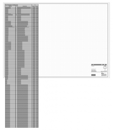
I have a reeeeeeally long worksheet generated from a load of data in my drawing. I want to display the whole thing on a sheet, but because there is so much information it doesn't fit on the page, and as such I want to split the worksheet (probably a couple of times, and ideally with the headers repeating!) so that I can fit all the info on one page neatly. I also want to still be able to recalculate the worksheet. Is this possible?
-
Hi everyone. I am fairly new to VW with previous software experience mainly in ArchiCAD. I am working for a practice and we've discussed having multiple users in a single file/model working at the same time. Now, in ArchiCAD there is a Reserve and release method, where you can research elements of the model to draw, and request to use reserved components from other users, where they can than release, freeing it up to use. Does VW offer a similar method, to allow for multiple users to work from the same file at the same time? Thanks in advance
-
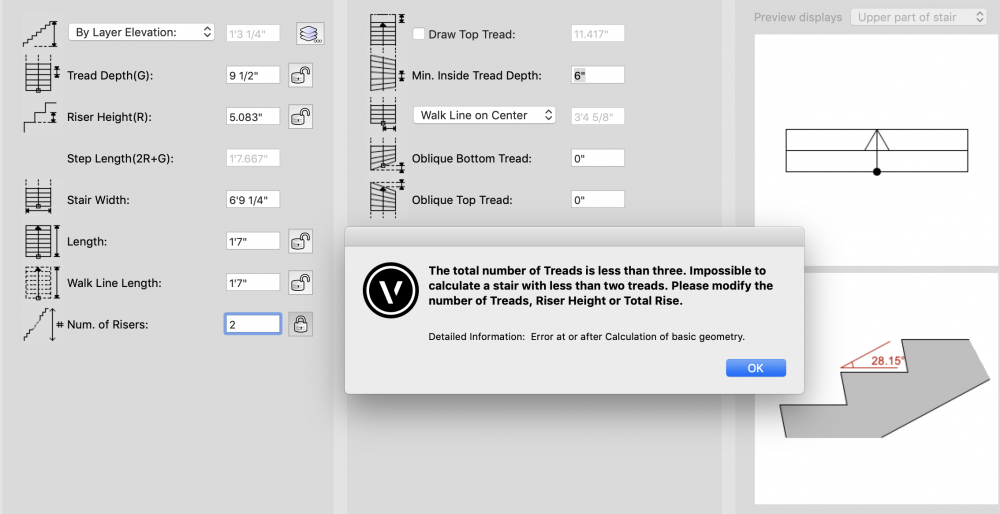
Hello world, We have a split level in our project and would like to model a stair with 2 risers and one landing, however, the tool will not allow for that. The rise should be 7.625" with 2 risers, not 5.083" with 3 risers, but I can't override the parameters. Any easy way to override? I started another topic where we tried designing a shipladder and had the same issue, where the shipladder can have a rise up to 10". I was able to modify the Min/Max setting for that issue, but am having trouble on this stair. Best of luck
-
What's the best way to coordinate an RC frame with a structural engineer. I've modelled our own version of the structure and we've been exchanging models, which I import into Vectorworks and then turn on and off to see any differences. I haven't really tried Solibri or BIMCollob ZOOM other than importing their models. Do these apps (or others) provide a better interface for highlighting differences?
-
Hi, I've been closely following VW's evolution in regards with BIM for the past 10 years. VW has made huge progress. Yet, what we REALLY need NOW is a good workflow allowing us to have a real and full integration within at least one of the well established OPENBIM platform. The 2 main players are, according to my knowledge BimCollab and BimTrack. While both of them have plugin fo full integration with Revit, Naviswork and even Archicad... there is nothing for Vectorworks. VW has always advertise its commitment to OPENBIM, so it seems that NOW is time to be able to help us have plugin to be able to work with those platform and catch the train ... Things are really happening now and I feel a sense of urgency, otherwise we are going to be ... too late. Could you let us know if the team has this kind of development in mind for a near future? Thank you.