Search the Community
Showing results for tags 'attributes'.
Found 20 results
-

DWG Import - Set all attributes by class
Ross McLee posted a question in Wishlist - Feature and Content Requests
Hi, Having spent an hour or so on the phone with one of your very helpful support team I thought it prudent to add this feature request to save time and effort for others in the future. I have imported several DWGs into separate reference files and used reference viewports to view/snap to them in my main working file. However I want to grey out these backgrounds in the sheet layers so that my content (not the architect's) is clearly visible against their background. By using viewport class overrides this should be possible (setting the line and fill colours to grey). I was advised today that this only works if ALL the reference file objects have their attributes set by class. The DWG import doesn't have an option to do this. Setting all objects to by class manually after the import doesn't always work well since the AutoCAD layer definitions (which are converted directly to classes - which is the right thing to do) may not have been used by every object in the drawing (colour by layer/fill by layer etc) but instead set manually. Is there any clever way around this problem (perhaps creating more classes where manual overrides have been used). Creating and using classes based on an objects current line type/colour/fill type/colour etc to create a class automatically and apply the same class to objects with identical attributes and then setting all attributes by class? (I envisage hundreds of 'sub-classes' being created) The other problem arises when dealing with hatches. AutoCAD, unless I am mistaken, allows you to use hatches where the hatch line colour is determined by the layer, VW has individual hatches one per colour if needed .... adding to my problems. I went through and changed all the pen colours and set them to grey (but I don't think that a good idea). Love to hear your thoughts. R -
Hello Vectors, Is there a way to export the fill colour into a dwg export? As far as I know, if you set the line colour it will be exported as the fill colour. In this case I want to have it the other way around because I mostly use black line colours. This means that all my symbols will be exported as white.
-
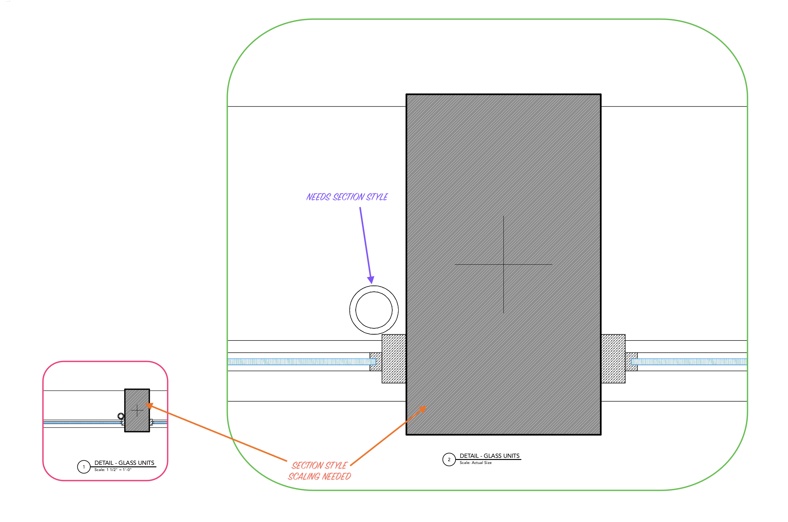
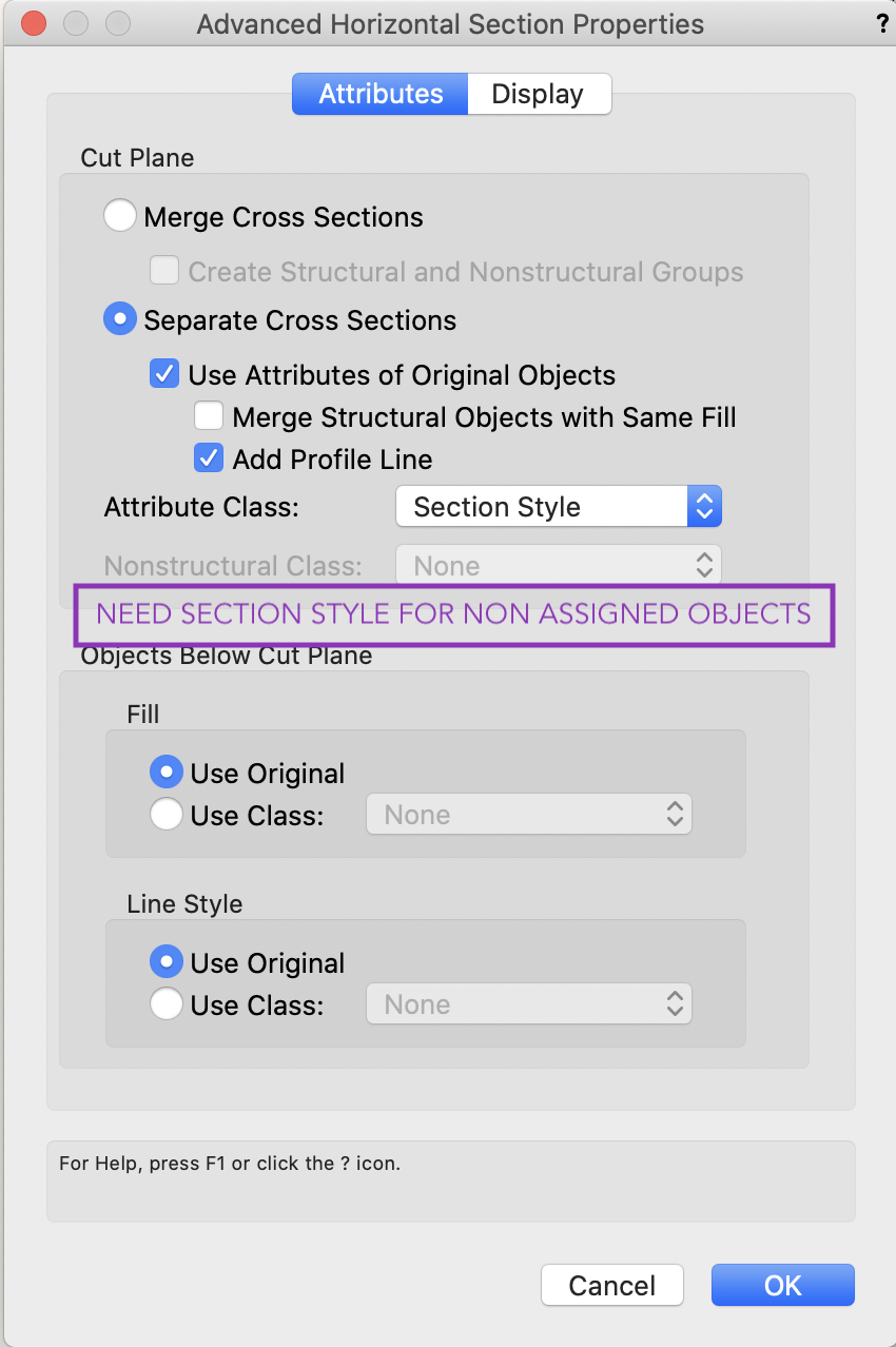
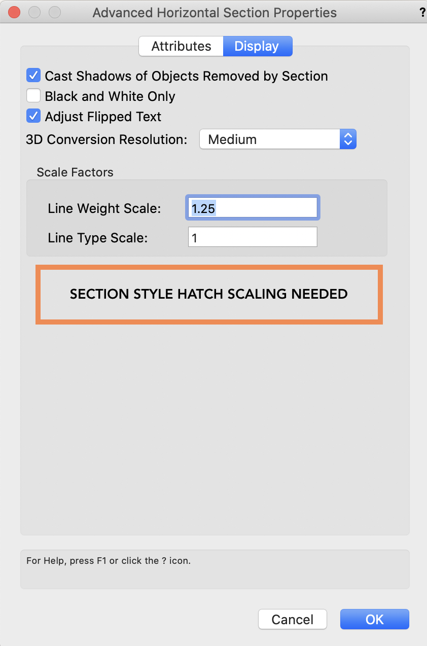
 I am proposing two additional functionalities for Advanced Section Properties: 1) Hatch Style Assignment for Objects where none are assigned. When selecting "Use Attributes of Original Objects" in Attributes of Advanced Properties - allow assignment of a section style to any objects that have not been assigned a section style. In attached screen grab I've assigned materials to glass and aluminum of windows. The column tool was used and displays a hatch. But the pipe extrusion I've drawn (and pointed to in purple) I have not assigned a material or a class and so it appears white, or without a hatch. I would like the ability to assign a default hatch to any non assigned objects. 2) Scale Hatch In a top plan viewport you are able to scale not only line type and weight but also hatch style. When Sectioning the Hatch Scale does not appear in Advanced Properties Display options. This is critical as hatches, especially in a full size detail, can become very tight and need to be scaled. Choosing an appropriate hatch for the object can work well for one scaled viewport but not another and should be adjustable for each viewport.
-

VWX 2020 Label Legend Manager Attributes Will Not Apply
Suzanne_de posted a question in Troubleshooting
Hello, I am having an issue with adding new attributes to my label legends. I have a fixture type that I need to add unit numbers to on my plot. I go into the label legend manager and go into edit fields for the label legend I am using for the fixture. I select the unit # attribute to use for the 2D and then I select done. If I immediately go back in and edit fields again it is still selected. When I go into edit 2D layout it is not there for me to place. When I go back into edit fields Unit # is no longer selected. I have tried making a new label legend and it does the same thing, but with any attributes I try to apply. So I am left with nothing to place. I have tried a using a different fixture type to build one, I have tried refreshing in-between selecting the attribute and going into edit it, I have tried restarting the program. It will not let me add anything to any of my label legends. Any help would be greatly appreciated. Again I am working in 2020. 20210316_075738.mp4 -

object attributes in a Data Tag
Bas Vellekoop posted a question in Wishlist - Feature and Content Requests
I would be a big time saver if it was possible to get the names of the object attributes in a data tag. A - The names of the fill styles: solid > color name hatch > hatch name pattern > pattern name and foreground and background color names tile > tile name gradient > gradient name image > image name when the fill style is set by class then then specified name in the class fill style B - The names of the pen styles: solid > color name pattern > pattern name and foreground and background color names line type > name of line type and name of color when the pen style is set by class then then specified name in the class pen style C - The line thickness D -The number of the marker Usercases: part B of this discussion: https://forum.vectorworks.net/index.php?/topic/79632-renderworks-textures-in-worksheet-name-of-color-in-a-data-tag/#comment-379286- 1 reply
-
- 3
-

-
- data tag
- attributes
- (and 3 more)
-
Hi vectorworks community, I wonder if people use standard naming tool (found in File>Document Settings>Standard Naming...) for daily work as a part of their office standard template...is it of any use and if yes is it reliable to do what it suggest? My main aim is to have classes in my own language - not english, ones that are coming automatically with certain inserted objects (site model, site modifier, roads, window, doors...) I have been experimenting little bit with these tool with mixed feelings so far. For example class name for site modifier will not change even if I have mapped it with custom name...still coming as: Site-DTM-Modifier What about copying objects from other files (ones with standard VW arch active ). Will it bring classes with that standard names or will it rename accordingly my custom standard....? What about class attributes that can be defined within dialogue...will it override existing class attributes? What is best approach to use this tool? Thanks in advance for sharing your experience.
-
I know this topic has been floating around in historic posts, but, I'm hoping someone can answer my question below unequivocally (feel a bit silly as I've been using VW for years): Within the Advanced Section Properties of the Cut Plane, can I have each object's respective fill be shown, and add a profile line to the cut elements? Seems I can either alter the settings to specify the profile line, or the fill, but not both. Have I missed something very basic here?
-
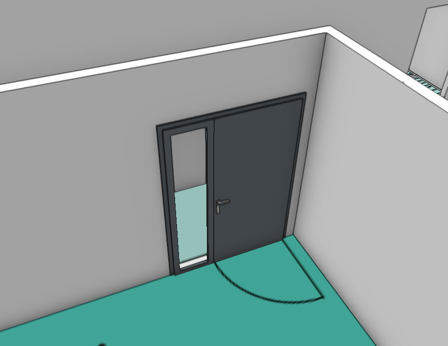
 Hallo everyone. I would appreciate some help. When it comes to a Door with a Sidelight, I can not seem to change the colour/material of the doorleaf so that it differs to the door frame. For example here below, i wish to have a white doorleaf however in the list of attributes available, the doorleaf attrubute incorporates the Sidelight as well. So that i end up with all white or all gray. The door frame easy to change. Have i done something wrong here. How else can i draw up a door with Sidelight so that the elements remain separate when it comes to attributes.
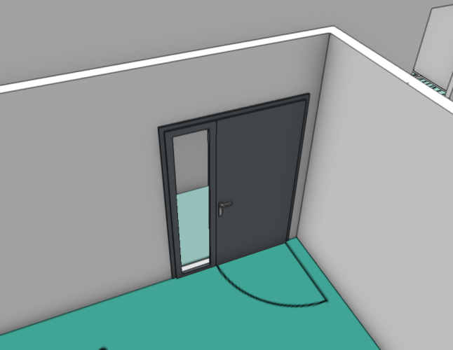
-
Hi, I'm hoping for an easy fix I've missed in my googling. I want to be able to change the colour/ attributes of a Marionette / object node from the object info panel or in such a way that it is easy/ quick to customise. Thank you for any help in advance. Kind regards, George Marionette - 4 Square.vwx
-
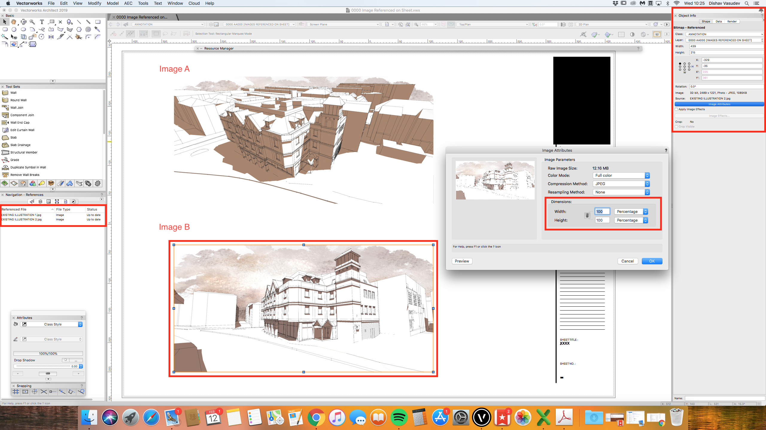
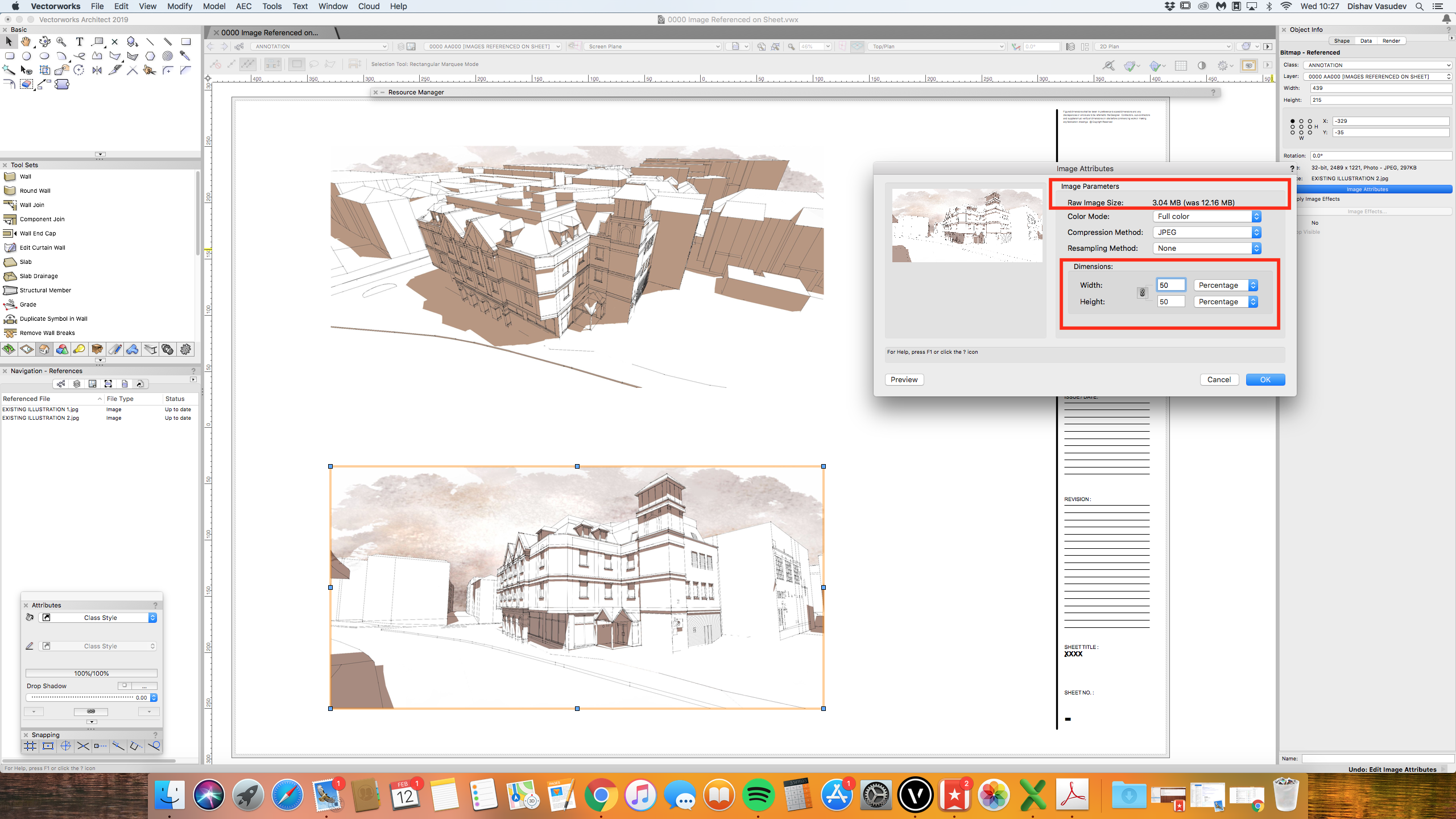
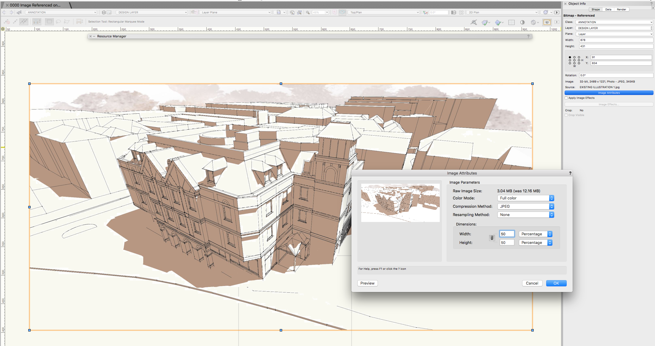
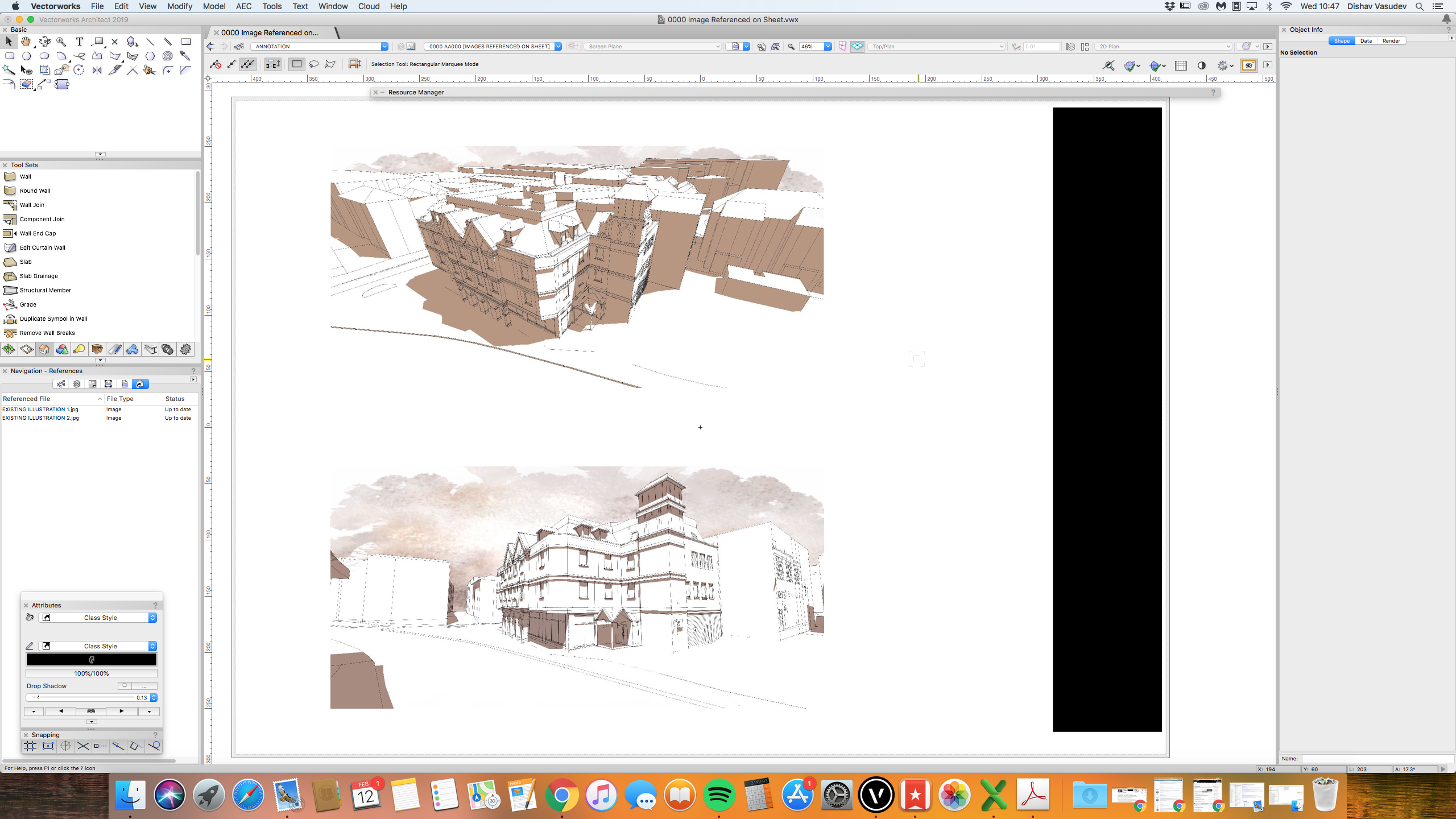
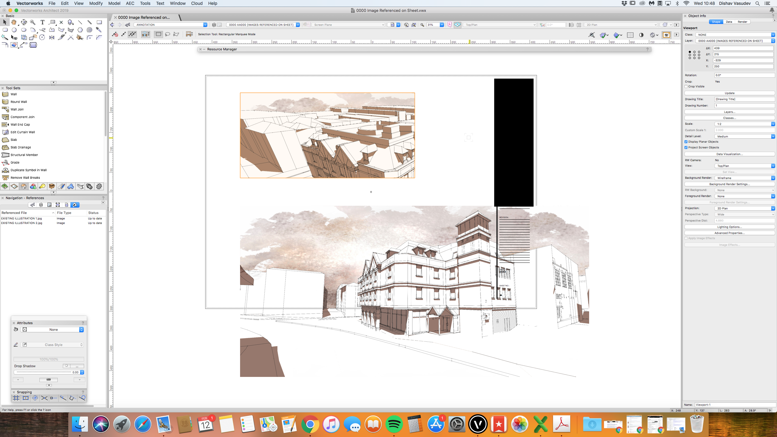
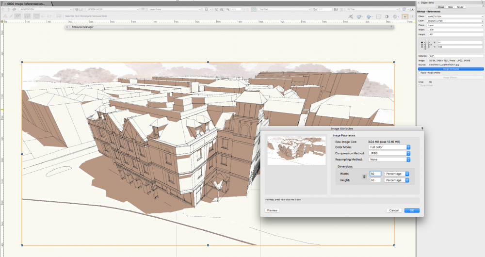
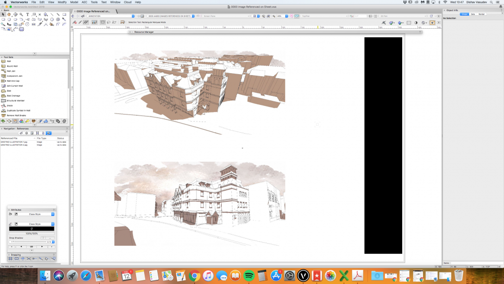
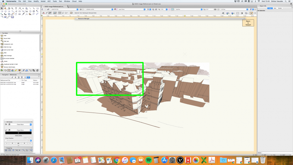
 Has anyone noticed; - when referencing an image into Vectorworks (either Design Layer or Sheets) and changing the 'Image Attributes' - 'Dimensions' from 100% to 50% to reduce the file size (note Raw Image size of Image B becomes 3MB from 12Mb). - then I go an export the PDF (attached) and there seems nothing wrong....at first! The problem / glitch happens when I close the Vectorworks file after saving and re-open the file (at another time) to find the images that were referenced in to have suddenly changed scale. One of the screenshots below shows a green bounding box on the Design Layer, and this indicates to me the images has gotten bigger. Twice as big. After a few testing, I noticed, what ever percentage I changed the Image Attribute to, it won't save the attribute I have set when I open the file. I have tried to lock the image and it would not work. I have many options I could think of, but somehow this feature of reference image only works if the 'Image Attribute-Dimensions' is untouched, which seems odd. The only reason I have to change the size is to reduce the image size, file size, PDF size when exporting to clients. I find it very odd that this is the mechanics for referenced image. Many Thanks for your time reading this topic. 0000 Image Referenced on Sheet.pdf


-
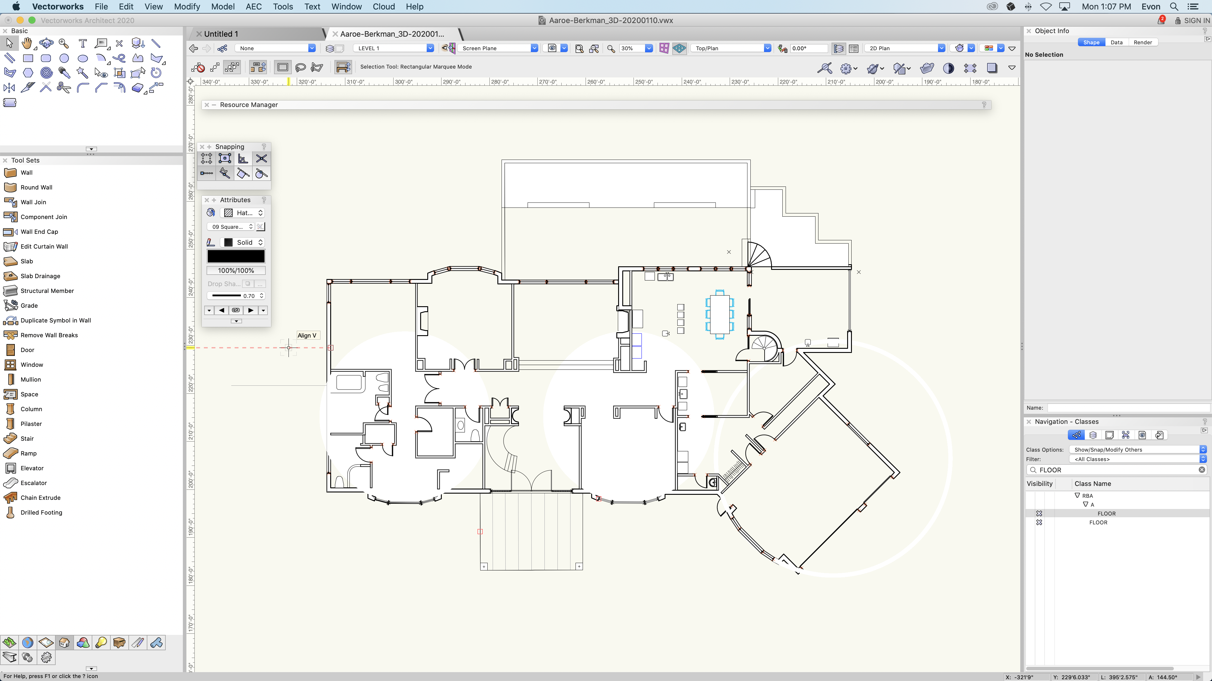
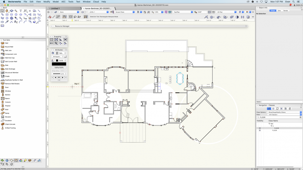
Hi All, I'm having an issue where the round/arched walls in my building are not displaying a solid fill correctly. In the screen shot below I have three bay windows on the south side (N is up); you'll see the two round walls on the left show an entire circle filled in even though the wall is only narrow arch, and the bay window to the right is showing a white filled ring. Currently the walls are set to "unstyled" but I have had them set to "10" generic" with a simple fill and had the same issue. I have tried re-modeling them as unstyled, styled, and replacing the style. When I first draw the wall it appears correct, it is not until I switch views and come back to my floor plan that the filed circles/rings reappear (which makes me think this is a bug). I did create saved views for my plans but I have navigated to them without using the "saved view' drop down to ensure it is not a weird visibility setting. In the plan it is not a big deal to just give the walls no fill but this causes my 3D views and elevations to not render correctly, any advice is welcomed! I'm running Vectorworks 2020 on a iMac 🙂
-
Something happened with graphic attributes in space tool. It seems impossible to have a label 100% opaque and 2D boundary in less than 100% opacity. This functionality was working in VW2018 but 2019 and 2020 has rearranged info and settings boxes and it is no longer possible. Its kind of indispensable when dong planing and color coding different uses etc.
-
Does anyone know why my drawing isn't showing some of the class attributes referenced from the source drawing? For instance, I've adjusted opacity and colour for paving but the adjustment won't show in my drawing no matter how many times I update the reference.
-
I am trying to do a simple thing: have space tool elements different attributes via classes. Class assignment is working fine, however, it seems like pen and fill cannot have different attributes, namely, I am trying to have fill @ 5% and label @ 100% opacity - space sits on top of everything else with label being 100% sharp and area fill color coded but showing furniture etc behind. Is it just me or is the label tool working that way.
-
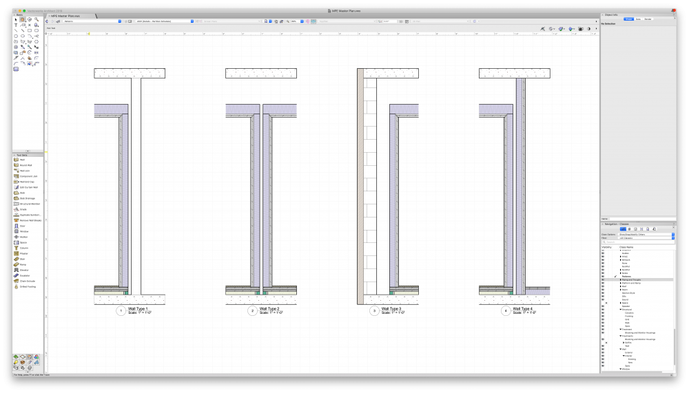
Hi all! I'm having an issue where not all geometry is being represented in a section viewport with the same line type and weight. I've attached a screenshot. I have four slabs represented in each of these viewports — two concrete slabs on different stories, a floated floor, and an interior ceiling. The lower concrete slab and the ceiling are representing with an open-end whereas the floated floor and the upper slab are "closed" and have a border around them. The two concrete slabs are the same slab style and in the same class but appear with different styles. I can't for the life of me figure out where this is modifiable from. Any help is appreciated!
-
So I have a class structure set up and therefore set my attributes to 'class style' but I have noticed that this changes and I'm not sure what key I''m pressing or what action I'm carrying out that is changing this? Any ideas? Its driving me crazy. I guess sometimes my active class changes to others too sometimes - I might start drawing on my '1 EXTG Walls' class and then all of sudden it might be back to my '0' class?
-
Good afternoon, After taking a look at the Titleblock elements for VW 2018, it is indeed flexible, however there is an issue regarding exports. Normally, when any symbol is exported with record information - in autocad it automatically converts it to attributes that can be modified for the symbol - very convenient when setting up standards in between two platforms. What I like - Before record information exported on a multiline field automatically converted to a single line field which made it impossible to modify multi line text without dramatically modifying the exported titleblock. This issue seems to have dissapeared, but for a different reason i believe. Now - with the new Parametric titleblock - the record information is there, however it is not exported as linkable attributes in autocad. In other words, record information for the symbol is there - however, attributes assigned to the text do not modify the text anymore. I believe it is because it was converted to a parametric record - not a database (modifiable) record. I thought I'd share this because it was quite handy to work in between platforms that links records and attributes together. Parametric constraints however do not. Perhaps theres a fix i don't know about? Either way, Thanks for the help in advance!!
-
Hi, I have a current issue with 1 particular drawing, it was working fine then all of a sudden everything is black and not showing the class attributes? or any colour, (it shows colour in ogen GL just not in Wireframe) i haven't changed any features unless by an accidental hot key combination that i am not aware of, for some reason all my Class Attributes are being over ridden and only displaying black on all. I have checked everything including display black and white only, all is as per all my other drawings, it literally happened in-between saving, closing and re-opening the file, has anyone ever seen this before. using VW 2017 on OSX 10.12.5 Class_Attributes_Issue.mov
-
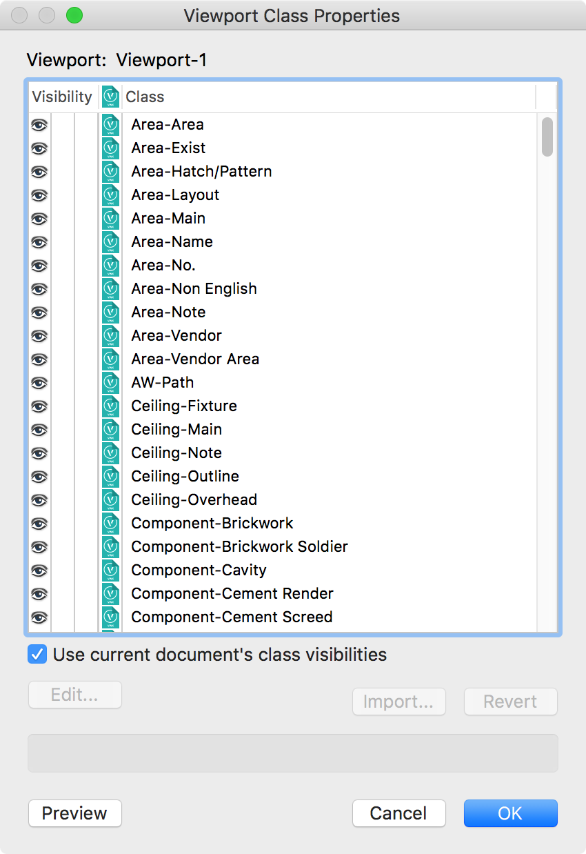
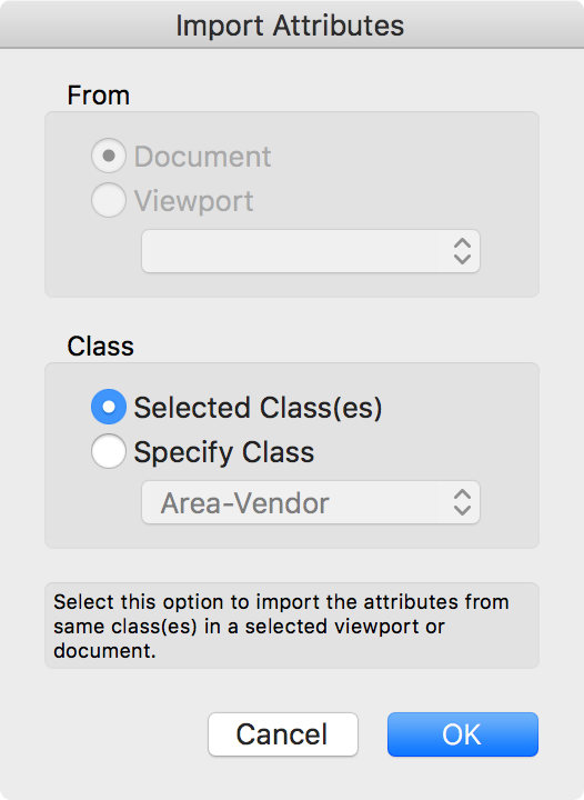
Hi Guys, Have been looking at the import attributes dialog (select Viewport > OIP > Classes… > Import…). What is the purpose of the Viewport Class Properties > Import Attributes dialog? There are some features of this dialog that make sense. These are – : Importing attributes from referenced Viewports. Maybe having referenced viewports take on the attributes of their residing document? Transferring Class overrides between Viewports. Any others you can think of? But what I am trying to get my head is, "Why would want to import Class attributes from the document Class attributes? Isn't this the same function as the Revert button? Any clues as to it's purpose?" Thanks. From Vw Help Opens the Import Attributes dialog box, to import the class attribute settings from the file. The attributes can be imported for the classes selected in the Viewport Class Properties dialog box, from corresponding classes, or from a specified class in the file or a specified viewport. Click OK to import the class attributes into the selected viewport. (The Eyedropper tool can also transfer class override attributes between viewports.)

-

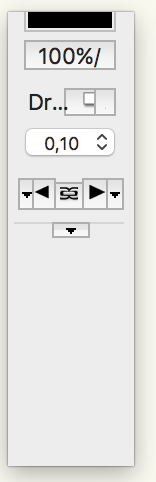
VW2017 Attributes Palette window resizing bug
Antoine D'Halluin posted a question in Troubleshooting
Hello, when I resize the attribute palette ; it crop a part of the palette simultaneously as it resize the text and the boxes (seems to be proportional). then you have no access to the hidden part of the palette. I cannot scroll up or down. for example, I have reduced the size of the palette from the top ; then it has cropped a part of the top. and then I tried to increase the lowest part ; it just generated some white part bellow the palette. see picture joined. Is it linked to my config ? to Mac Os config ? to some config error in my VW config ? thanks PS I am using VW2017 on Mac OS 10.11.6.