Matt Panzer
-
Posts
3,328 -
Joined
-
Last visited
Content Type
Profiles
Forums
Events
Articles
Marionette
Store
Everything posted by Matt Panzer
-
Actually, I retract my statement. :-) Modifiers in VW 2017 are added the same as in VW 2018. The difference is that VW 2017 will allow modifiers to be added even when they do not overlap the slab's true boundary. VW 2018 seems to add them only when they overlap the boundary. I'm thinking this IS a bug. Submitting it now...
-
I believe this is by design. Edit the Slab's Boundary and you will notice only for the original slab shape. Edit the slab Modifiers and you will see the objects added. When these objects are added (using Add Surface), they can effect any number of user selected components of the slab object - so they do need to be treated differently. However, If you Edit the Slab Boundary, place an object over the boundary object, then Add Surface, you will then add it to the boundary. -Matt
-
This is a known issue and should be addressed very soon.
-
You’re welcome, Niki! Thanks @Christiaanand @Gadzooks It’s always interesting to see the many clever approaches from you folks on the boards. :-)
-
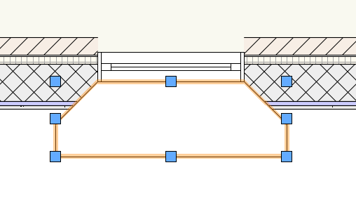
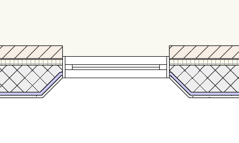
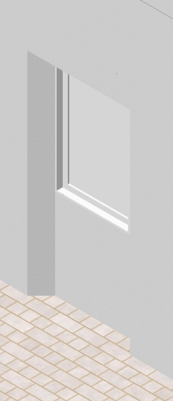
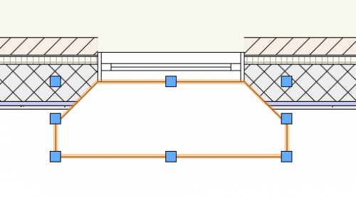
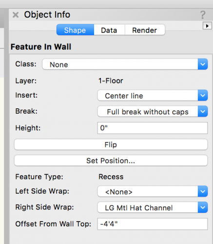
Another variation on this with a Wall Feature: Create a 2D polygon, select it and the wall, and use the Clip Surface command. A wall feature will be created. In the Object Info palette, set the Right Side Wrap to the desired component and set the Offset from Wall Top to get the niche to align with the top of the window. This method does creates pretty good Top/Plan graphics and also carries the outside component finish into the cutout in 3D.


-

Door and Window Catalogs missing from Resource Manager
Matt Panzer replied to HawaiiFarmer's topic in General Discussion
You’re welcome! You can find a lot of videos of 2018 features here: http://www.vectorworks.net/training/2018/getting-started-guides -
Door and Window Catalogs missing from Resource Manager
Matt Panzer replied to HawaiiFarmer's topic in General Discussion
Our Door and Window content now takes advantage of the new Door and Window Style Catalog feature in Vectorworks 2018. This allows us to provide much more content than in previous versions. Catalog content is accessed through a Door or Window Style. The basic workflow is to insert a Door or Window Style from our content, edit the style, rename as desired, and choose a product from the catalog. Here's a quick (silent) video showing how it works: ScreenFlow.mp4 -
Roof object line weights do not show up in 3d views
Matt Panzer replied to P Retondo's topic in General Discussion
Setting the line weight of the components should give you what you need. -
VW 2018 - Unexpected error in Viewport showing 3D solid object
Matt Panzer replied to Martin Tye's topic in Architecture
Hi Martin, Hover the your cursor over my name at the top of this message and a small popup will appear with my information. At the bottom left of that popup, click on "Message". You should be able to attach the files to the message by dragging them into the message.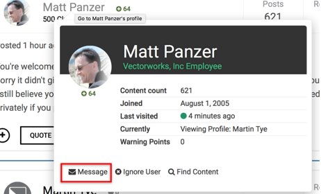
-
VW 2018 - Unexpected error in Viewport showing 3D solid object
Matt Panzer replied to Martin Tye's topic in Architecture
You're welcome, Martin. Sorry it didn't give you the results you're after. But good to hear you can get what you need from Final Shaded Polygon mode. :-) I still believe you should be able to get something useful using the steps I mentioned. Would it be possible to attach the file (or send it to me privately if you prefer not to make it public)? -
VW 2018 - Unexpected error in Viewport showing 3D solid object
Matt Panzer replied to Martin Tye's topic in Architecture
Try setting the Background Render of the viewport to OpenGL (with Draw Edges turned off in the Background Render Settings) and the Foreground Render to Hidden Line (with the Smoothing Angle as needed in the Foreground Render Settings). This will give you the shaded quality of the OpenGL (raster image) with the vector lifework of Hidden Line on top. Also, Keep in mind that Raster render types (OpenGL and Renderworks) use the sheet layer DPI. If things look too fuzzy or pixelated, edit the sheet layer and set its DPI to something higher. The default is only 72. -
VW2018 Roof lights
Matt Panzer replied to Max E's question in Wishlist - Feature and Content Requests
We hear you on this and do have this high on our list. In the meantime, you might want to give the Velux Skylight plug-in a try: You can download it from here. BTW: The download button for the plug-in incorrectly states "Download Vectorworks models": http://www.veluxusa.com/professional/products/modular-skylights/cad-bim/vectorworks -
Hi John, Another good wish! You may want to add these wishes to the Wishlist forum. :-)
-
You're welcome!
-
Hi JMR, In the Data Vis dialog, I see two records being used. The one using red attributes is the "Rough Opening Width" of the Door record. Try removing that to see if it gives you what you're after.
- 5 replies
-
- 1
-

-
- data visualization
- custom records
- (and 1 more)
-
You're welcome, John! My guess is that the style cannot be changed in the worksheet because it's treated differently than a "normal" plug-in parameter. Nevertheless, it would be nice to have that ability.
-
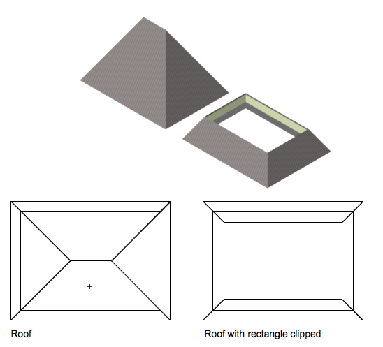
Create a Roof object In Top/plan view, draw a rectangle over the roof for the flat area Select the Roof and the rectangle Use the Clip Surface command from the Modify menu Fill in the hole as needed (with a slab, low pitched roof, parapet walls, etc)...
-
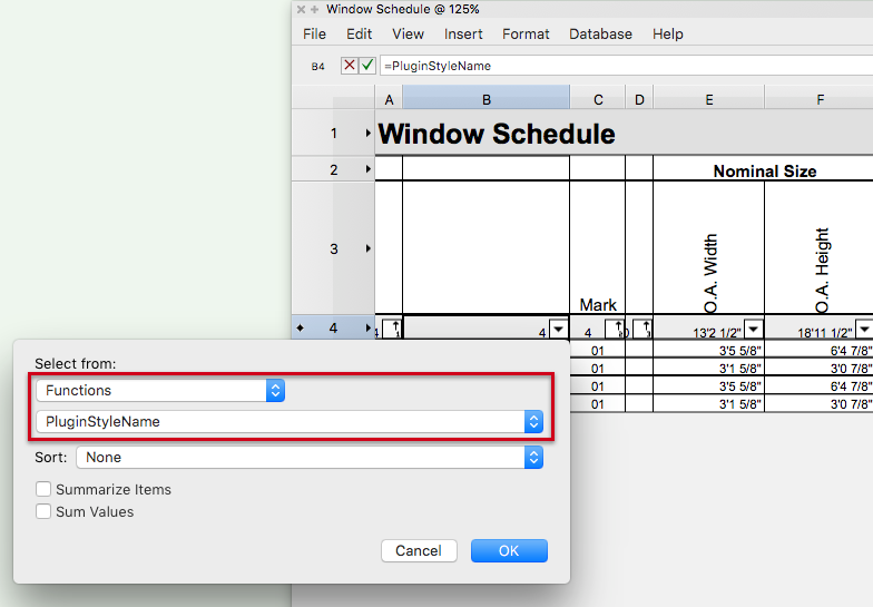
Hi John, Try the following steps: Add a column to the worksheet, Toggle on the View Database Headers Click on the popup menu in the database header for the column Choose: Select from: Functions PluginStyleName Click OK and you should see the style names.
-
Wall components not showing in viewport
Matt Panzer replied to Allen Brown's question in Troubleshooting
No problem, Allen! I only knew the answer because it happens to me as well. ;-) -
Can a roof opening be edited or deleted??
Matt Panzer replied to Sinead V's topic in General Discussion
Your'e welcome, Sinead! Having objects windup on another planet happens to the best of us. ;-) If things seem to be acting up with display accuracy, checking for this issue is a great place to start. -
Wall components not showing in viewport
Matt Panzer replied to Allen Brown's question in Troubleshooting
Are all of the "Component" classes set to visible in the viewport? -
I have to agree with the others that Option 1 is the way to go. This is especially true is you have symbols containing objects in more than one class. It'll be better to get them all on board with this standard sooner than later. BTW: There's a "Set Default Symbol Class" command in the Tools/Utilities menu. This will allow you to set the default class for ALL symbols in the document. It does not effect placed instances, just the default. Just remember that it will effect ALL symbol definitions. :-)
-
Can a roof opening be edited or deleted??
Matt Panzer replied to Sinead V's topic in General Discussion
Hi Sinead, I got your file and see the problem (and have the fix): The distortion you're seeing is due to the file have some objects very far from the document origin. If you ever see this problem, usually that is the reason. Here's the fix: With the "Ground Level" layer active, use the "Select All" command to select everything. Use the Zoom "Fit to Objects" command. You will notice that you see what looks to be a locus point at the top center of the document and nothing else. That "locus" is actually all the objects from your model contained on the layer. While the objects are selected, notice the number of objects selected in the Object Info (172). Using the selection tool, deselect those objects at the top of the document by holding the shift key and click-dragging a marquee around them. In the Object Info palette, you should now see 2 lines selected. These lines are near the bottom center of the screen (2,480,043,659mm from the document origin). Delete the lines and the file should render normally again. Best, Matt -
Option 1 is what I’d recommend. You can edit the symbol options and have it automatically insert in the None class. I typically have all my symbols insert this way and only worry about classing the objects within them.
-
Can a roof opening be edited or deleted??
Matt Panzer replied to Sinead V's topic in General Discussion
@Sinead V, Are you on VW 2018 SP1?