tsw
-
Posts
68 -
Joined
-
Last visited
-
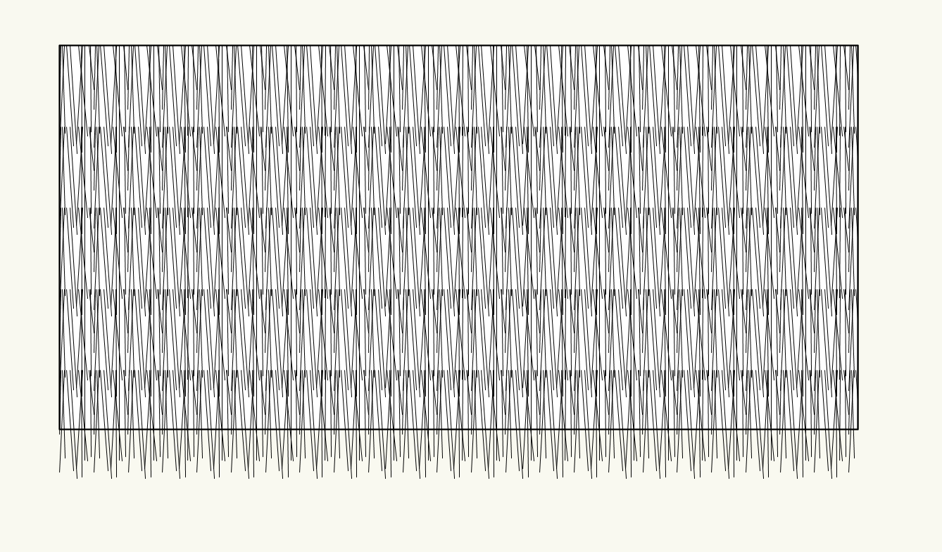
If you don't mind adding the thatch in the viewport annotations, you could also use a custom line type. thatch line.vwx

-
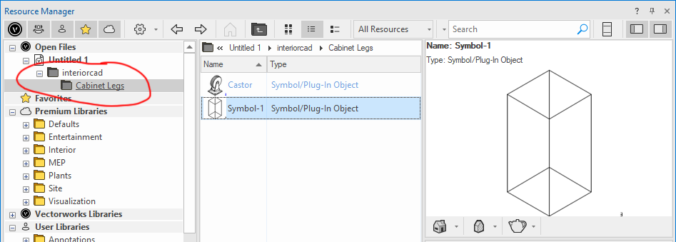
I was able to select a custom symbol after I moved it to the "Cabinet Legs" subfolder that is created when initially selecting a default leg.
- 1 reply
-
- 1
-

-
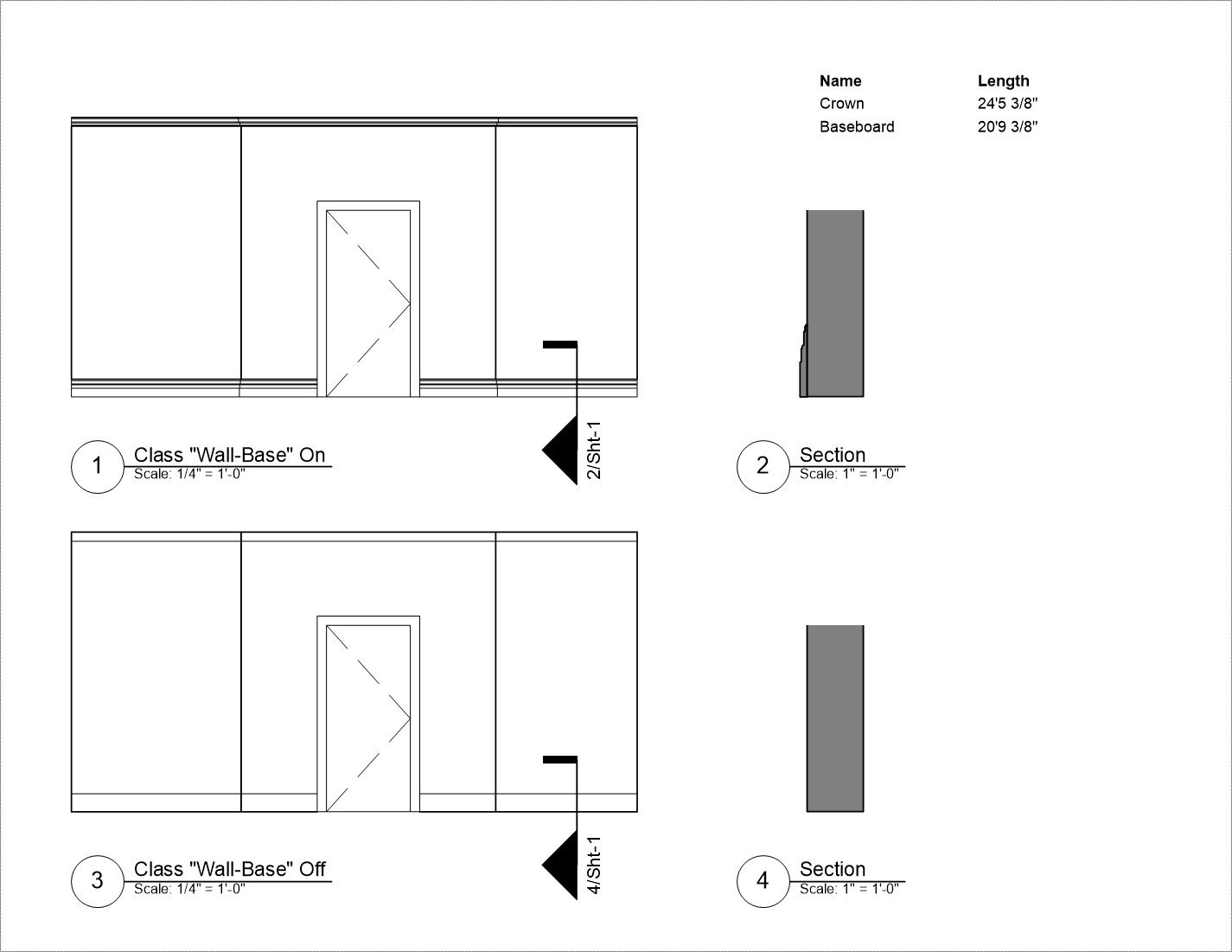
I've been searching for a better way to model baseboard other than the usual Extrude Along Path method. Using the Railing Tool, you can get to a solution that's fairly workable. A few advantages over the EAP method: Uses a 2D symbol for the moulding profile so you can update the baseboard for an entire project if it changes Can be set by Object Style, making universal changes easier (textures, line weights, classes, etc.) Using Guardrail-Frame settings and appropriately classed components, you toggle between a high detail 3D view and a simplified version for elevations Easy to reshape (including skirtboards on stairs) Query lengths to include in a worksheet if needed It won't cut around doors automatically and I haven't figured out a way to easily do window/door trim. Also requires some fussy one-time setup if you want to have a matching simplified representation. Other than that, it seems to work quite well. Examples in the attached file. Baseboard Example.vwx

-
Shaded view does not match Final Interior Rendering with brick
tsw replied to MGuilfoile's question in Troubleshooting
What projection mapping method is used for those objects? I've seen this happen with shader-based textures using the default Surface UV mapping. Try Auto-Align Plane and see if you get different results. -
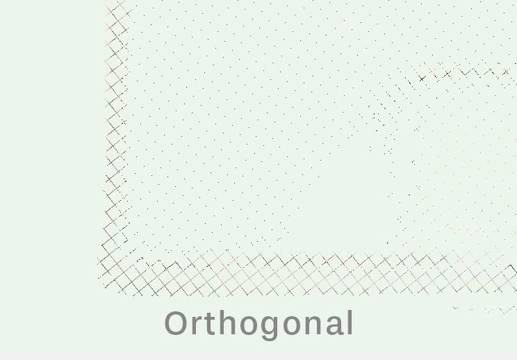
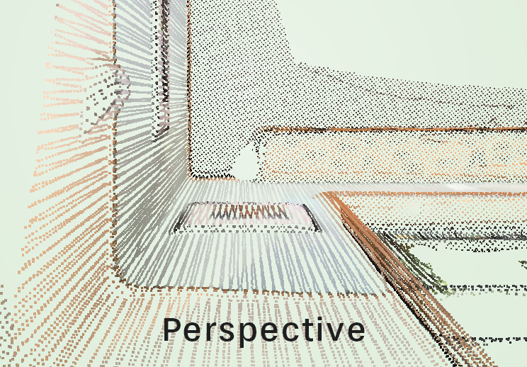
I've successfully imported a pointcloud object. When zooming in an orthogonal projection, the points are displayed as a single pixel, so it's very difficult to see what I'm looking at and to snap to points. However, in a perspective projection, the points appear at constant size irrespective of zoom. I would expect the points to always be a constant size, no matter what projection I'm using. Perhaps there is a setting somewhere that I'm missing? I think this is a bug, but posting here to see if there are any solutions. Images below are of the same scan in orthogonal and perspective views.
-
Thank you for the suggestion. I ended up doing something very similar. I left the Stair object as a PIO (otherwise it loses its story bounds) and made the handrail a separate hybrid symbol. I had to turn off the 2D representation of the Rail object and draw it manually so that it clips properly at the breakline. Unfortunately, that means if the rail changes I'll need to manually update the 2D view. It would be great if VW integrated the Railing tool with the Stair tool so we didn't need a workaround for a fairly common condition.
-
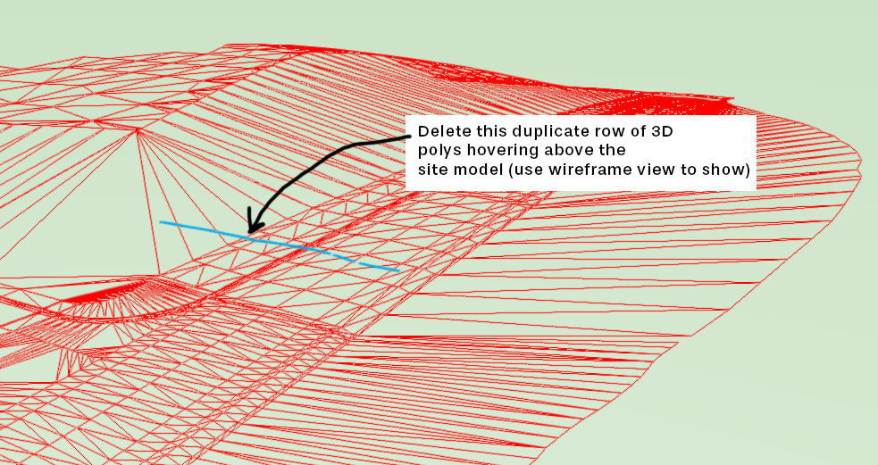
Great tips from Jeff on cleaning up your site model. Since the TIN data is essentially a complete mesh, I got similar results by entering Recreate from Source Data mode and deleting everything EXCEPT the 3D polys in the class "3DTIN-tin SUPER FS". (Select all by class and invert the selection, or lock that class temporarily and select everything else, etc.) Then there were just a couple errant polys in one corner I had to manually delete that are causing a weird bump in the model.
-
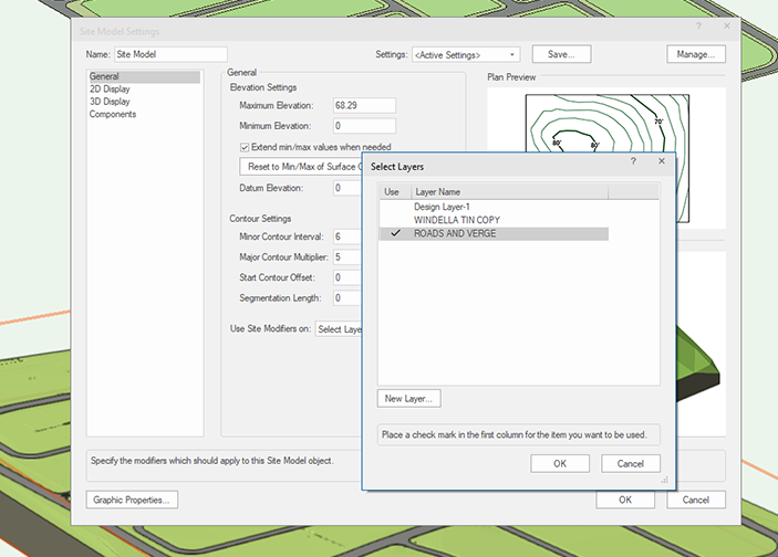
Here are the steps I used to get it to drape properly: Double check that the appropriate site modifier layers are checked in Site Model Settings: Right click on your Hardscape object and choose Edit Path With the path selected, click Modify > Drafting Aids > Simplify Polys... (I used a value of 5 for Minimum Distance) That simplifies the outer poly, but you'll need to simplify the inner shapes too, so go to Modify > Edit Polyline With the inner polys selected, run Simplify Polys... as before Exit the path and the Hardscape should drape.
-
A cleaner site model would probably help make it less fussy. However, I was able to get the hardscape to drape on your site model by simplifying the polyline. I'd guess there were colinear vertices imported from AutoCAD that were causing it to fail. I also had to check the correct site modifiers layer in the file I downloaded (not sure if it got unchecked when importing), so you might double check that in your site model settings. Here's the link to the file. I'll make another post with the steps I took to clean up/simplify the polyline: https://we.tl/t-0hwm5VVurM
-
Making a smooth transition (in 3d) between two NURBS curves?
tsw replied to line-weight's topic in General Discussion
This approach seems to work too: Draw vertical line/axis Mode > 3D Power Pack > Create Helix-Spiral Enter parameters (e.g. 1 turn for a complete circle in plan) Ungroup to get a NURBS Curve. This gives you a nice clean curve with interpolated control points BUT it loses "circular-ness" if you move the points too much Either increase Degree to 4 in OIP, or use Model > 3D Power Pack > Rebuild NURBS... to get an approximate but really close circle with the desired number of control points (look at the Maximum Deviation number to see how accurate the rebuilt curve will be) Move control points on Z-axis (to get close to your example, grab half the points and scale to 0 in Z-axis to flatten that part of the curve)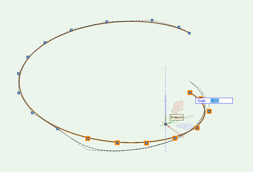
-
Making a smooth transition (in 3d) between two NURBS curves?
tsw replied to line-weight's topic in General Discussion
For this part, you could try the following: Draw circle Modify > Convert > Convert to NURBS Model > 3D Power Pack > Rebuild NURBS... Enter the desired number of control points Move point in Z-direction It appears to stay circular in plan—not sure if it's mathematically perfect though. I think it's very close if you rebuild with enough control points (but also becomes more difficult to manipulate). -
Is there a best practice for making multi-story custom stairway handrails display correctly in plan view? The handrail options built into the Stair Tool are pretty limited, but using the Railing Tool in Pick Mode I was able to quickly generate a handrail with the correct wall returns. However, I'm not sure how to get the 2D information to display the way I need it to on both the lower and upper floors. The image on the left is the 2D view of the model. On the right is what I'm trying to get, with the handrail clipped at the stair breakline. Any suggestions for the best way to achieve this—and hopefully still retain the parametric objects? I attached the .vwx file as well in case it's useful. stairs.vwx

-
Disappearing content when view is idle, reappearing while zooming in or out
tsw replied to Vilardaga's question in Troubleshooting
I've had this happen occasionally as well. I don't know what causes it, but as you said restarting seems to clear the problem. -
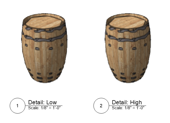
I'm also having the same issue with several different object types in VW2023 SP4. In the attached file, setting geometry detail to high or very high doesn't change how the model renders. The barrel top is a simple extruded circle and the hoops are sweeps—both exhibit the same behavior. 1738957525_barreltest.vwx
-
Vectorworks 2023 - major regression in section rendering…
tsw replied to GatRed's question in Troubleshooting
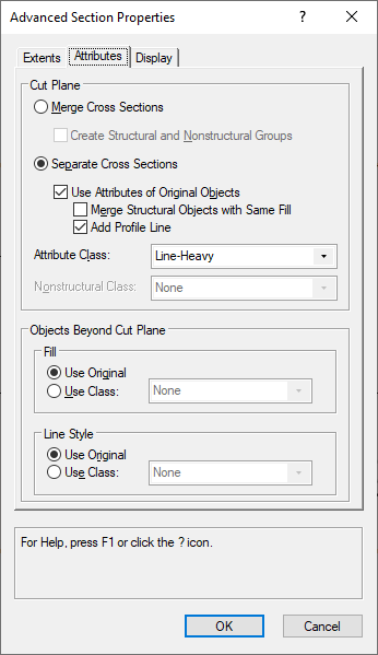
I don't know if this is related to the other section view issues above, but under Advanced Section Properties, the Add Profile Line feature no longer works in section viewports. Can anyone else confirm this is the case? (I am also on Vectorworks 2023 SP1.)