Tom W.
-
Posts
5,070 -
Joined
-
Last visited
Content Type
Profiles
Forums
Events
Articles
Marionette
Store
Everything posted by Tom W.
-
I thought I'd hate the Home Screen when they said it was coming but I'm actually very happy to have it. It feels weird when I open a file in VW2022 + it's not there...
-
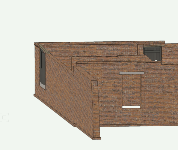
Just do it with the 3D Modelling tools: Multiple Extrude (Model menu), Push/Pull, Deform, Taper Face, etc. Then convert to Auto Hybrid or Hybrid symbol to get the desired Top/Plan representation. This is a project where I wanted a fairly accurate model of the existing architecture, which I modelled in the way above from a point cloud survey: But I then went on + modelled the proposed development 'properly' using the BIM tools as a separate model...

-
This would be great
-
Can you post some images of the wall in question? It shouldn't be difficult to model. Can I confirm that you're looking to model the project in 3D + are you saying that this is your first 3D project? Trying to incorporate irregularly shaped walls, etc in a BIM model can be a bit of a nightmare + it may be more pragmatic to 'square-off' the wall in question in order to create a satisfactory overall model + not give yourself a nervous breakdown in the process. It all depends what the desired end result is i.e. are you looking to produce detailed plans, elevations, sections + details from the model, report on products/materials, R-values, etc? Or is it more about creating 3D renders? Am interested to know as I am frequently working with old buildings which are all over the place as well.
-
This has reminded me: is there any reason why I can paste values into the 'Rotation' field when I use local mapping for a Hatch in the Attributes Palette...? You can copy + paste values in all other areas as far as I know (OIP, tool dialogs, etc) but not this one...
-
Just model the wall in question with the 3D tools then convert it to an Auto-Hybrid or Hybrid Symbol so that it resembles the Walls proper in Top/Plan. If you have 'Merge with structural objects in sections' enabled in the OIP for the 3D geometry it will merge with the parametric Walls in section VPs. To clarify, you're saying you have an overall model built using the parametric tools (Walls, Slabs, Roofs, etc) but have one particular existing wall which is too irregular to represent using a Wall right? It kind of depends somewhat on the model as a whole + how easy it is to integrate the irregular geometry with the parametric geometry.
-
Definitely not all 3D objects! Thank you. NURBS + 3D Polys only I think. Plus Edit SubD as well of course
-
Is it to do with column A being Summarized?
-
What version of VW are you using? The 3D Dragger was introduced with VW2023. It is only an option for 3D objects so you wouldn't see it with a 2D Polygon but if you have VW2023 it should be there for a NURBS Curve.
-

Window offset by style not working in one file
Tom W. replied to Tom W.'s question in Troubleshooting
Ok great thanks. I was able to set the Tile by class so all was not lost. And main thing is I wasn't going mad 🙂 -
Window offset by style not working in one file
Tom W. replied to Tom W.'s question in Troubleshooting
I can't say that I have. It's not something I need to do very often. It has definitely happened before - probably in VW2022 - but I think I thought at the time it was a problem with Materials. It's only today that I narrowed it down. Thanks for looking into it. -
Window offset by style not working in one file
Tom W. replied to Tom W.'s question in Troubleshooting
Thanks Matt yes be happy for you to look at the file. Do you need to DM me a DropBox link or something? Whilst I've got you would you be able to check something else for me? - Open a new file + create an Extrude. - Apply a Tile Fill to that Extrude in the Attributes Palette. - Convert the Extrude to a Generic Solid: object fill changes to 'None' + any attempt to assign a Tile to the object fails (other fills are fine). The only way to assign a Tile to the Generic Solid is by class. The same applies if you perform a solid operation on the Extrude (it loses the Tile Fill). Is this happening to you too or am I going mad? Thanks! -
@Kevin K were you actually deported to Tahiti? 😁
-
Can you draw a single Polyline then use the Offset Tool?
-
You mean you want to backfill over the footing? This isn't really possible in a practicable way. See:
-
Easiest way to call out the top-of-wall elevations in plan?
Tom W. replied to Ed Wachter's topic in Architecture
Using the B key (X-ray Select Mode) can help when it comes to selecting the right object with a Data Tag -
Window offset by style not working in one file
Tom W. replied to Tom W.'s question in Troubleshooting
No you didn't. It works for me in a new file too: in fact in all my files bar one as far as I've noticed. The file is quite large + was created originally in VW2021 which might not help. At any rate, at least pretending to edit the style seems to force the PIO changes to take place so isn't completely dysfunctional. Thanks for looking at it anyway! -
Easiest way to call out the top-of-wall elevations in plan?
Tom W. replied to Ed Wachter's topic in Architecture
I'm not sure about the existing Data Tags but in VW2023 you can use the #ZTBBG# function to return the top of the wall relative to the ground plane. This is also available in VW2022 but not in VW2021 unfortunately. Here is a sample tag in VW2022: Wall Elev Data Tag v2022.vwx -
Not at all. See https://app-help.vectorworks.net/2023/eng/VW2023_Guide/Symbols/Creating_2D_components_for_symbol definitions_and_plug-in.htm
-
Easiest way to call out the top-of-wall elevations in plan?
Tom W. replied to Ed Wachter's topic in Architecture
Yes -
The 2D + 3D components of a symbol are completely independent of each other so you have to manually check they are aligned. If you select '3D' in 'Show Other' in the Component Edit palette you can check the 2D is aligned with the 3D. It is easy to create a 2D component then move the 3D component + forget to go back + move the 2D component as well.
-
In the elevation you are looking at the 2D component of the symbol so check that this is at the right height relative to the 3D component...
-
How to buy an InteriorCAD update?
Tom W. replied to Ride's topic in 3rd Party Services, Products and Events
Ok you're talking about attempting to use IC23 on VW24? But using IC23 on VW23 then importing the Cabinets into your VW24 file would be ok right? Without having Interiorcad loaded I can import Interiorcad Cabinets that other people have sent me + use them in my models, I just can't edit them. -
Select the Mesh then go to Modify > Scale Objects... Here you can either scale the whole object equally using 'Symmetric' mode e.g. enter '2' if you want to double the size. Or scale it differently in different directions using 'Asymmetric' mode e.g. in Front/Left/Right View enter X Scaling Factor of 1 + Y Scaling Factor of 3 to make the object 3 times taller.
-
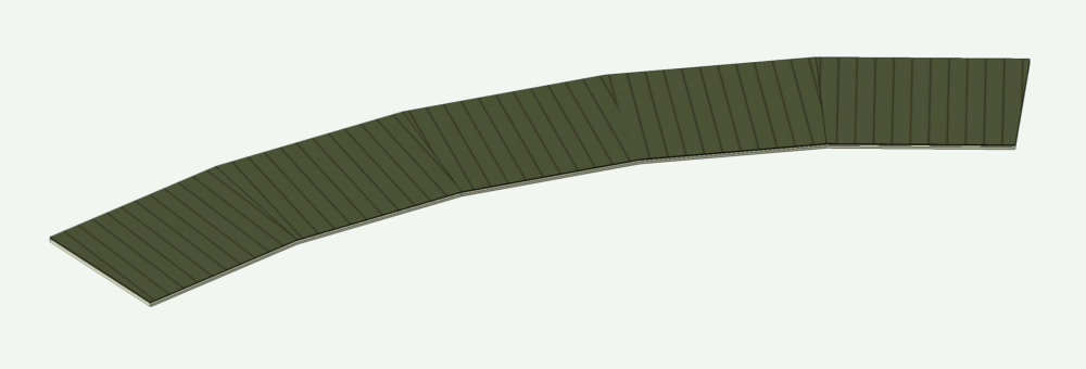
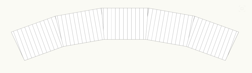
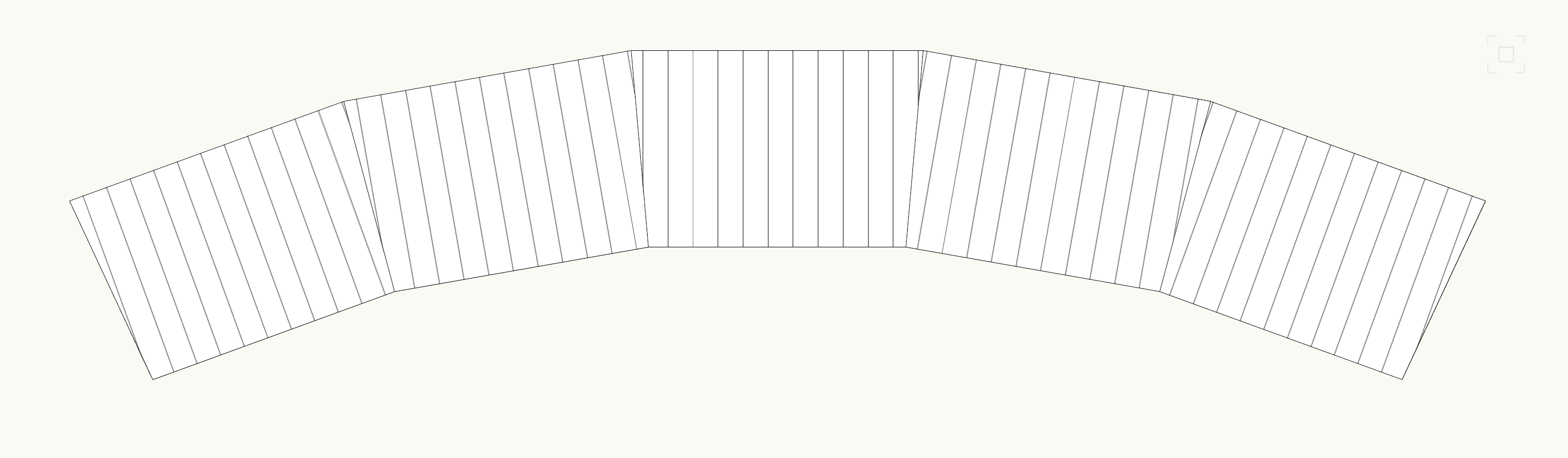
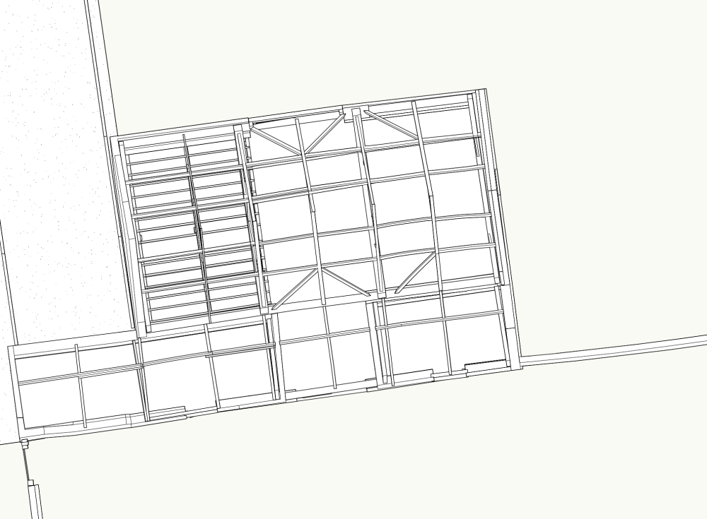
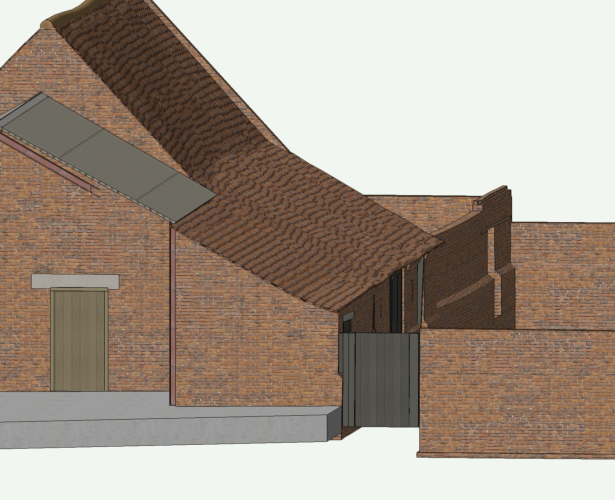
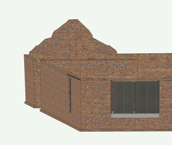
I thought from the screenshots that the seams were arranged radially, hence my question about being able to represent this in a texture (I should have said radial rather than tapered). You could build the roof radially if using lead or zinc. Or EPDM probably. But whichever way it's built the roof structure itself is likely to be segmented rather than a flowing curve. It's clearly segmented in the screenshots. So I'd probably construct it using Roof Faces + either use a standing seam texture if I wasn't overly worried about the joints between the segments: Or have a flat texture + add the seams afterwards as 3D solids for a more accurate representation.