Tom W.
-
Posts
5,070 -
Joined
-
Last visited
Content Type
Profiles
Forums
Events
Articles
Marionette
Store
Everything posted by Tom W.
-
 I have been playing with 'Create a room plan with Lidar' on Nomad. From the article linked above: I got the .USDZ file but no .OBJ file - presumably because I had no internet at the time? I assumed that once I had wifi the opportunity would re-present itself but I could find no way of sending a .USDZ file off to be processed into an .OBJ file. But seeing as I can import .USDZ directly into VW is there any reason to...? What is the benefit of importing the scan into VW as an OBJ instead of a USDZ? Why didn't I get an OBJ automatically as the article suggests? Why couldn't I generate one after the fact? Thanks!
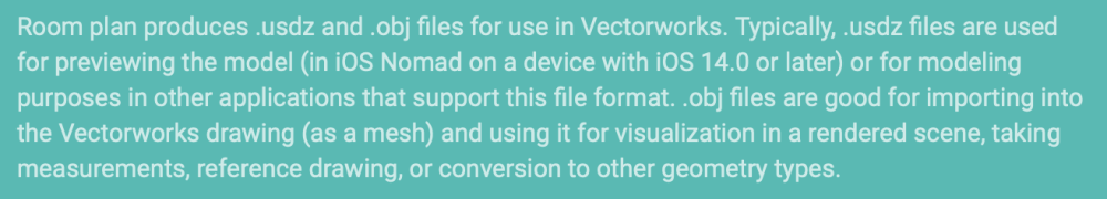
-
Associative Dimensions and Parallel Constraints
Tom W. replied to rudybeuc@gmail.com's topic in General Discussion
In that case you can just have them as separate tools in the tool set, they don't all need to be children of a parent. Or add them to to your Smart Options Display if that's an easier way to access them. Although they do work on moving Walls in 3D via the Dim value, which was one of the examples in the orig post...- 9 replies
-
- 1
-

-
- associative
- associative dimentions
- (and 1 more)
-
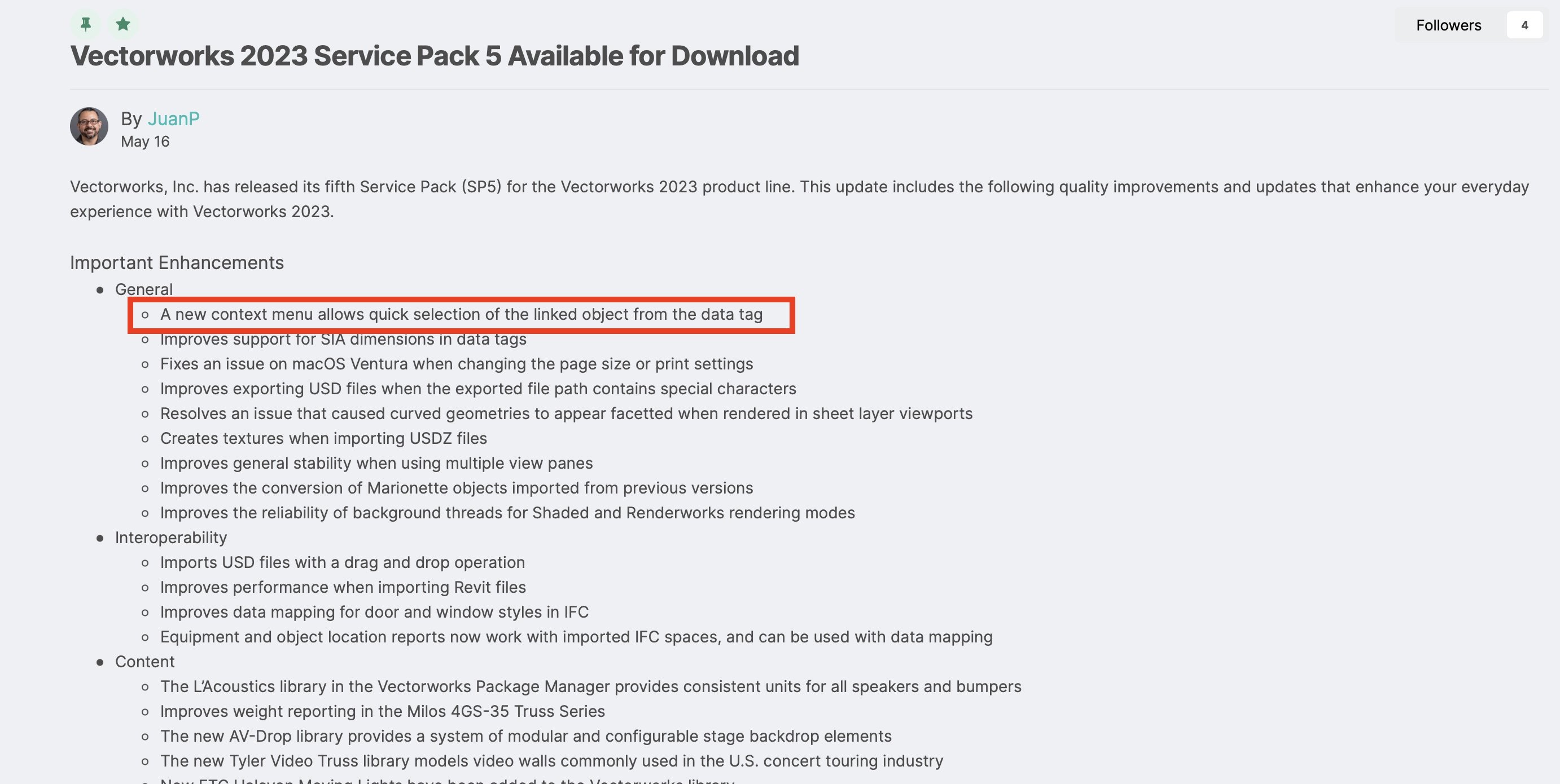
I agree this is great addition. It was new with SP5: It felt like no sooner was it discussed + requested than it appeared! Thank you VW!

-
If you want to edit the default values attached to a symbol definition you need to use @Pat Stanford's script in the thread I posted. But doing this won't affect existing instances of that symbol, only future ones.
-
Can you just set up a worksheet that searches for those symbols in the drawing then edit the values in the worksheet?
-
Have a look at this thread: Are you talking about changing the default field values for the symbol definitions or changing the values for multiple instances of those symbols? Either way, that thread covers it.
-
Associative Dimensions and Parallel Constraints
Tom W. replied to rudybeuc@gmail.com's topic in General Discussion
You can edit the toolset to make 'Constrain Horiz-Vertical' the parent if you want. -
Can we create sheet layer folders?
Tom W. replied to MattWhite's question in Wishlist - Feature and Content Requests
I agree. This has been asked for many times. See: Also: I personally would find it really helpful to be able to use colours/highlighting in the layers lists to be able to differentiate between different types of sheets. I'm sure there is a wish for this too but couldn't find it.- 1 reply
-
- 2
-
-
Associative Dimensions and Parallel Constraints
Tom W. replied to rudybeuc@gmail.com's topic in General Discussion
Previously, were you constraining the two objects first?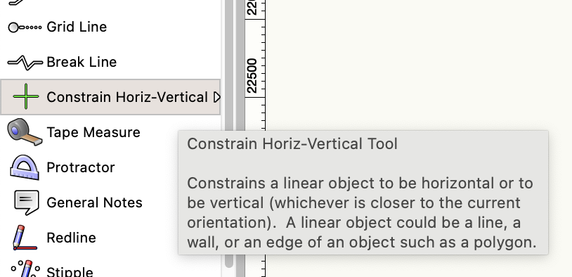

- 9 replies
-
- 1
-
-
- associative
- associative dimentions
- (and 1 more)
-
What workspace are you using? I think Mosa has been around since VW2020 actually so should be there...
-
Do you need to edit your workspace?
-
No it's been there since VW2021 I think...?

-
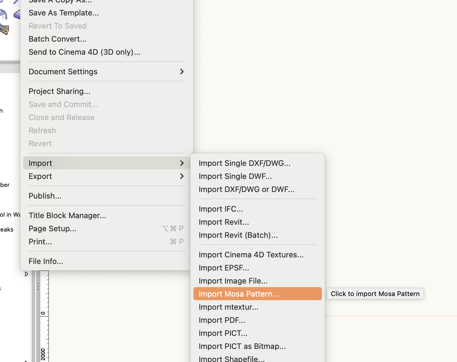
You could also have a look at the Mosa Pattern Generator (File > Import > Import Mosa Pattern...). It allows you to create lots of different tile textures + automatically creates a matching single or double line hatch at the same time (although you still need to apply it as a surface hatch yourself)
-
Window offset by style not working in one file
Tom W. replied to Tom W.'s question in Troubleshooting
Many thanks Matt. Unfortunately in my full version of the file neither 1. nor 2. have any effect on the problem. I still need to 'pretend' to edit the window style in order for the style-based offset change to take effect. I don't really understand how that particular SLVP affects things as the same layer is present in a number of other SLVPs: or is it to do with the scale of the VP + the large geographical area it covers? Anyway I have recentred the drawing on the Internal Origin as there was no particular reason for the geometry to be where it was other than that's how my template file is set up. Everything was within the 5km optimum working area or whatever you pros call it but nevertheless it feels better to now have it slap bang in the centre of the drawing! I have had some other weird things going on so we'll see whether they still happen. Thanks for looking at it + reporting the bug. -
VW 2023 - Window PIO Issue - Insertion Points / Offset in Wall Depth
Tom W. replied to zoomer's question in Troubleshooting
What are you saying no longer works + is permanently greyed-out? This is probably another case of a parameter being By Style rather than By Instance. This is how Styles work. -
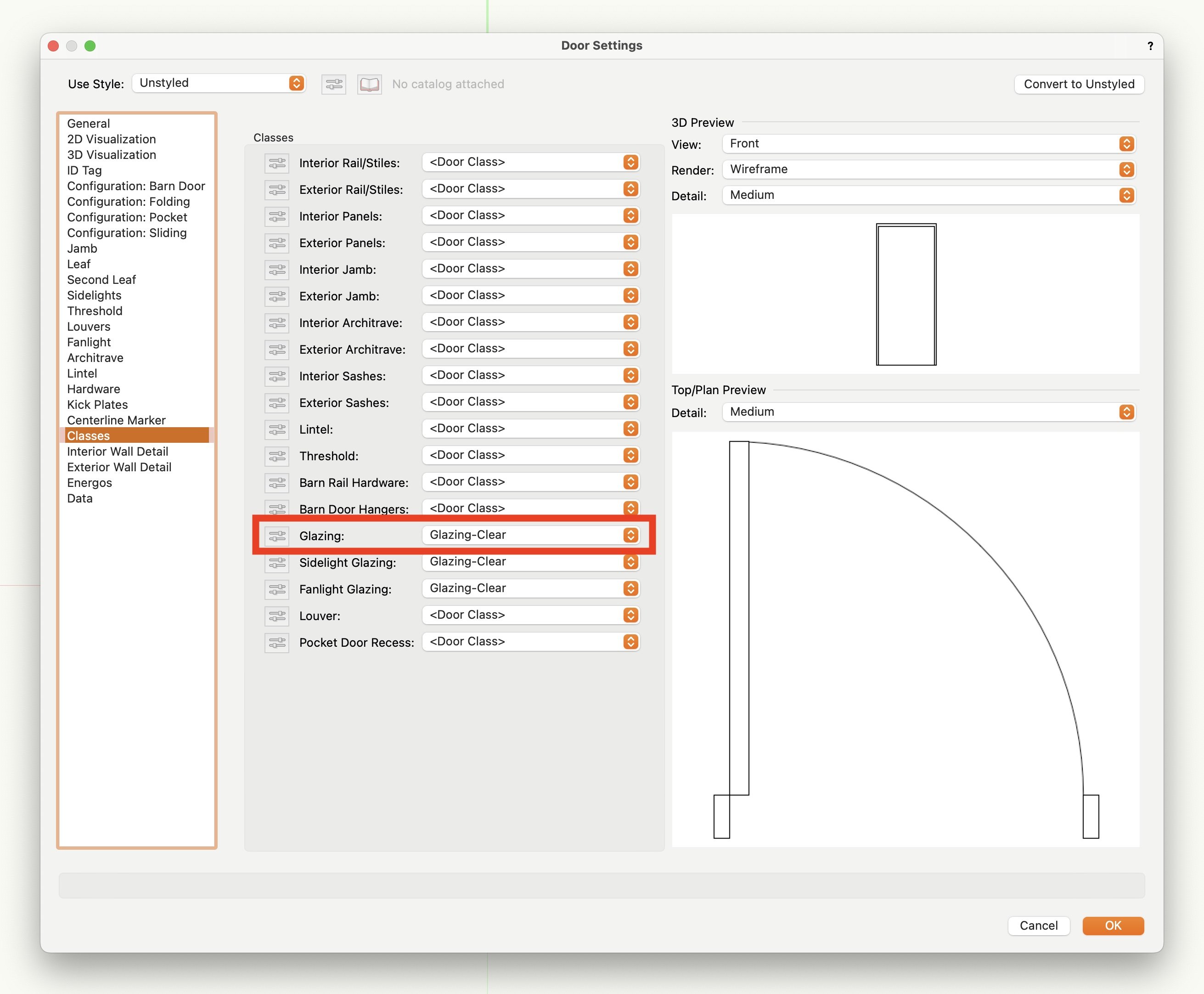
Classes tab:
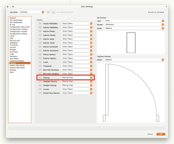
-
I have noticed this too + wasn't sure whether it was just me or I'd done something wrong...!
-
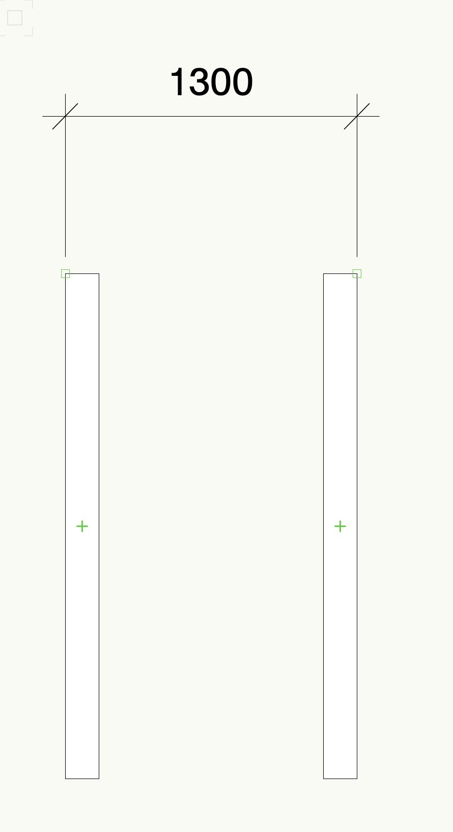
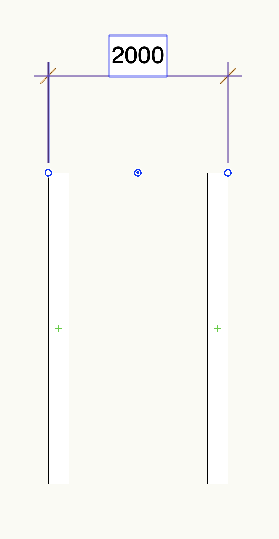
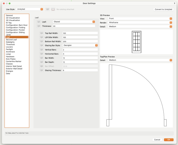
Is this what you want? When you say most of the settings are greyed-out is it because your door is Styled rather than Unstyled?
-
Wall component graphic behavior changes when part of a symbol
Tom W. replied to EliM's topic in Architecture
That's interesting well discovered! I never turn Unified View off so would never have noticed that... -
Wall component graphic behavior changes when part of a symbol
Tom W. replied to EliM's topic in Architecture
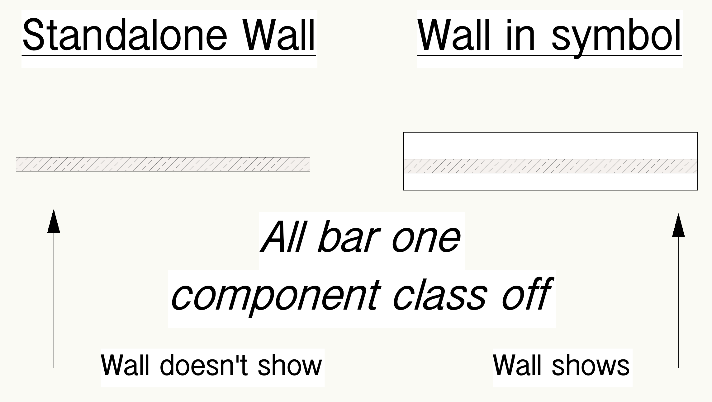
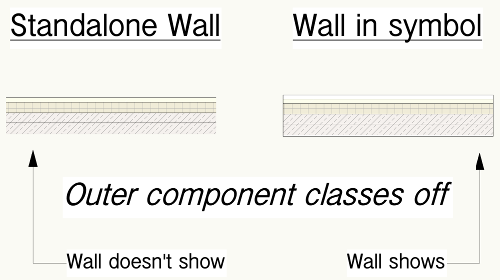
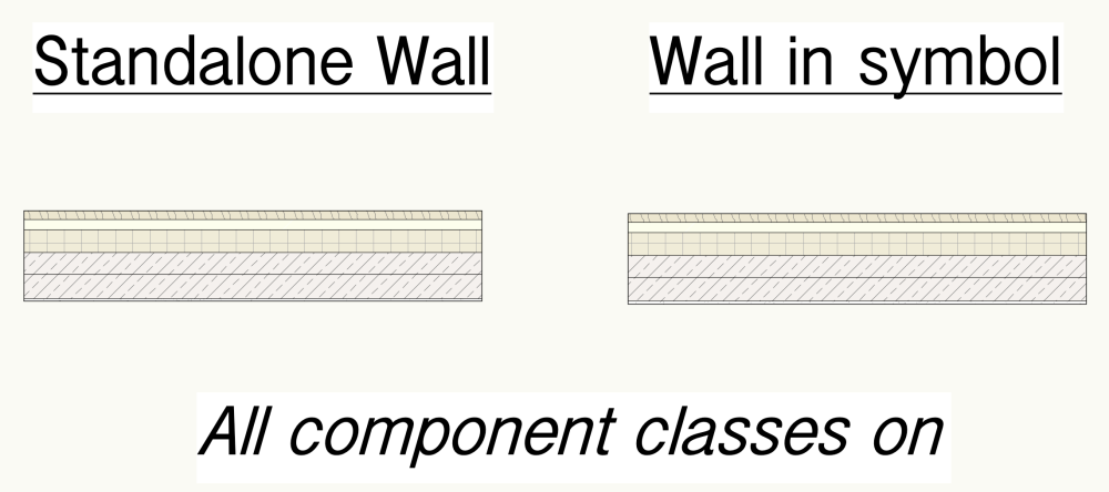
It seems that the behaviour of the Wall class visibility (the visibility of the container class) changes when the Wall is converted into a symbol. Normally, if you make the first or last component class invisible the Wall class will also become invisible but this doesn't happen if the Wall is symbolised. See: So I think what's happening in your case is that the interior finish is turning off, it just looks like it's still on because you are seeing the container class (the Wall class) behind. I realise this doesn't help... Perhaps it should be submitted as a bug?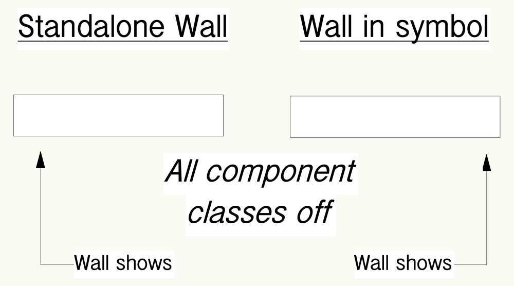

-
Yes please. Please vote up:
-
Difference btw =WALLAREA_NET and =WALLAREA_GROSS?
Tom W. replied to Ramon PG's question in Troubleshooting
There is this on the University for Materials: https://university.vectorworks.net/mod/page/view.php?id=1177 Not sure if I watched it or how useful it is. Sorry I didn't look at the screenshot last time so missed the weird values. Not sure what's going on. What is the formula in E4? Post the file if you like -
Difference btw =WALLAREA_NET and =WALLAREA_GROSS?
Tom W. replied to Ramon PG's question in Troubleshooting
WallArea_Net returns the average area of the interior + exterior face of the Wall, adjusted for holes. WallArea_Gross returns the average area of the interior + exterior face of the Wall, ignoring holes. Have you considered using Materials? They are purpose made for reporting quantity, costs, product details, etc in conjunction with Walls/Slabs/Roofs. If not I would use ComponentArea instead as this returns one side of the component. -
Do you mean by setting the negative overlap such that it clips the whole section of Wall under the door? If so that's a very neat trick thanks for sharing!