BartHays
-
Posts
161 -
Joined
-
Last visited
Content Type
Profiles
Forums
Events
Articles
Marionette
Store
Everything posted by BartHays
-
Turbosquid models - textures not importing
BartHays replied to ajemutt's question in Troubleshooting
You likely have to rebuild the textures in VW. Most Turbosquid models are not set up for the way VW handles texturing. Is VW creating textures in the Resource manager? Sometimes it will create the textures but can't find the images do they are all blank. If that happens, look at the *.MTL file(text file), that comes with the *.OBJ file. For each texture, make sure it lists an appropriate texture map: "map_Kd Texture_162.png" or similar (the Kd is for Diffuse or your base image map in VW) If all the parts are there, you can recreate the texture in VW, Chances are that the mapping will work because it is baked into the geometry. You just need to get the right image maps into the textures. If you don't have an MTL or it doesn't list diffuse textures then you have bigger issues. Or, if you have an MTL file but no images, that can be another problem with how Turbosquid packages download. Bart -
Ah, yes, this is a PDF issue and has to do with how the PDF creator handles transparency "layers". We see this a lot in graphic design. Depending on how you view/output the PDF the Transparency "layer" can be misinterpreted as semi-transparent. Rasterizing or flattening the PDF merges the transparency layer with the color layers that will typically get rid of the problem, at the cost of also rastering vectors and type. if you really want to target transparency in the scenario, you can try using Acrobat ( or some other PDF editor?) and File>Save as Other>Optimize PDF and tick the Transparency box, and choose the [high Resolution] option. Bart
-
Yup We usually have a series of layers with a Z-prefix for junk/reference info. Bart
-
Why not just make a template file with all of your sheets set up? you could prefix the sheet names with a Z- in the template and remove the prefix as you populate the sheets - making it easy to know which sheets to publish put the template file in your defaults folder and each time you start a project, use the template instead of a blank file. Bart
-
//insert sarcasm font// Have you tried ChatGPT for this? I am sure it would solve all of your problems. Bart
-
Similar problem with my version, I just mirrored the slats so they intersect to get the "look" But I thought, similar to how the OP started, bending a rectangular prism was more likely to make something "buildable" than extruding along spiraling curves, I just had to make sure you were only ever bending along one axis. If you created two shells offset by the thickness of your material and built the second set of slats off of the second shell it would be even better, In the end, If I were in the shop, I'd throw all the drawings out and start prototyping. 😁 Bart
-
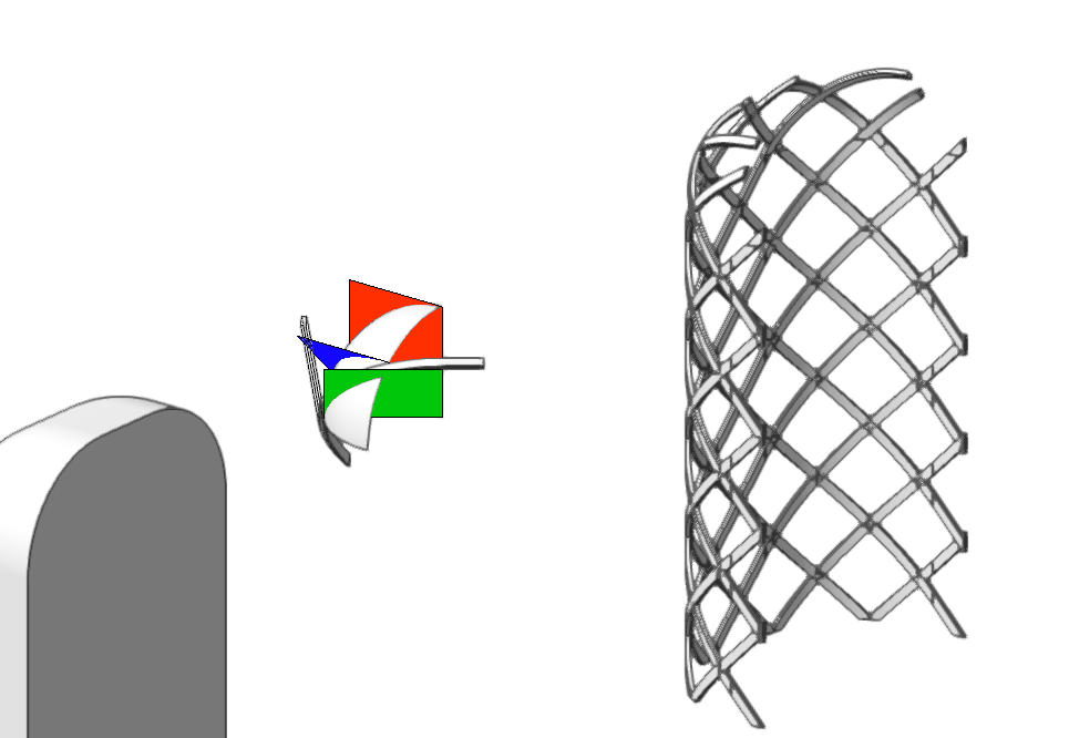
Well, it is a slow weekend so I thought I would play some more with this, One of the keys, as you say above, is that it has to be buildable - so bending a solid makes sense, But figuring out the bending planes is where it gets complicated. I think I figured out the proper way to define the bend plane. See attached: Looking just at the Spherical radius, create a plane that cuts through the center of the sphere to one edge ( my RED plane) in a front view, rotate the plan 45 degrees to match the angle your strips will run. (BLUE) In a TOP View, rotate the plane (BLUE) to match wherever your strips intersect the sphere (GREEN plane) This is your bending plane. I started with a fresh, unbent, strip, at a 45-degree angle and matched in position to where the strip starts to overlap the sphere. It might take some more explaining, and I found problems where the strips converge as they wrap the sphere, (think longitude lines on the globe, But here is where I got before I had to make dinner : Arbor.vwx
-
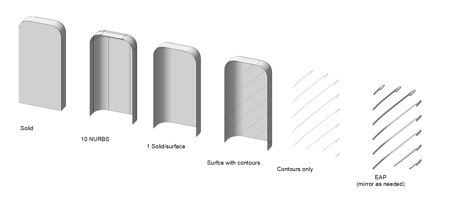
Cool problem, I think you are on the right path with creating a NURBS surface. After you have the solid, extract the NURBS surfaces, you'll get 10 or so surfaces, then use Model>3D Power Pack>Stitch and Trim. This will make them one surface/solid. Then I would use the Create Contours tool to slice the surface win the diagonal lines you can use for an Extrude Along Path. The only trick I see is that the EAP is hard to get to lay the way you need to - this may render my whole solution useless. I haven't played with it enough. Bart

-
As far as I know, it is the same slab object. There are just two(or more?) ways of getting the same output. Glad it worked! Cheers, Bart
-
Looks like the non-closed wall is(EDIT: ISN'T) the issue, but here is how you can create a boundary object polyline and then convert it to a slab ( Assuming you have VW Architect or better) Maybe try turning your stair class off while you try to create the slab. Bart
-
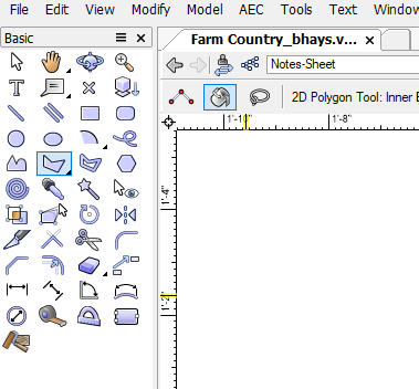
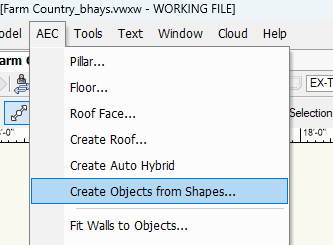
Have you tried to create the poly first (inner boundary mode) and then convert it to a slab object via "create Objects from Shapes? It's hard to see but is it possible you don't have a close boundary? Bart
-
Unshaded Polygon No Lines render mode needed
BartHays replied to Christiaan's question in Wishlist - Feature and Content Requests
I wonder how you would feel about Renderworks> Artistic>cartoon, with the line weight set 0.01? You do get textures - not just flat color, it is pretty fast, WAY faster than unshaded polygons in my test. Then you can add hidden lines over the top for crisp lines ( if you want them) I like to add a heliodon for some nice shadow effects but you can turn off all the lights to omit shadows. A version with lights and HL over the top Bart
- 15 replies
-
- 2
-

-
- unshaded polygon no lines
- final unshaded polygon
- (and 1 more)
-
Are you using indirect lighting? That sounds like it might be bouncing light off of the graphics and into your scene. Do the graphics have a "Glow" shader that might be emitting light? can you post the file so we can help diagnose it?
-
@kevinK Do you have trouble with the image prop not taking on the lighting of the scene? My experience is that they tend to look like poorly photoshopped plastic overlays if you don't assign them reflectivity via making a texture. Obviously, your Piccaso looks very good. Many thanks, Bart
-
Sketchup is the worst if yuo need to do any manipulation of the object textures. Generally, SketchUp files are junk geometry. With that said, any mesh object can be pretty tough to work with in VW. VW is known to have difficult texture mapping tools. in your above image, it looks to me like a mapping issue. Possibly the Stainless texture is getting remapped and tiled. I might try to use the texture mapping tool to make sure all of the faces that use that texture are mapped to the whole door, not just the individual faces. OBJ files have been the most reliable for mesh models. though the new USDZ seems like there is potential to replace OBJ if it really catches on. Best, Bart
-
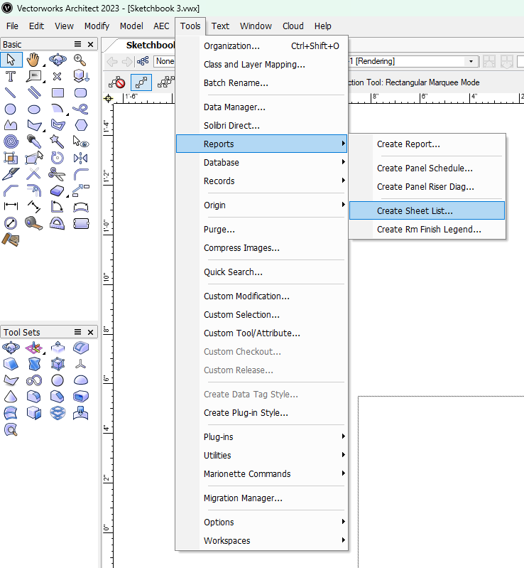
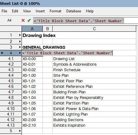
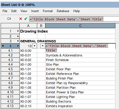
if you have Architect or above: This is not super dynamic, you'll need to recreate it if you add new sheets. Alternately, Create your own Worksheet using data extraction formulas: Cheers, Bart
-
Detail Viewport Selection way too large
BartHays replied to Cal.Scenic's question in Troubleshooting
My guess is that the Crop object is not working correctly. Or, Can you post the file? Bart -
Modeling 3D object - Material/textures and 2D color
BartHays replied to Cristiano Alves's topic in General Discussion
Or, of course, you could just use the TOP[numpad 5] view not (Top/Plan)[numpad 0]. Depends on what you are looking for. Bart -
I guess the first thing to know is that STL files don't carry a measurement system. If you make a 4 foot cube in VW it will get exported a 48 "units" - I am assuming your VW file is set to Inch/foot units based on your use of 1/4" and 1/2" scales When you import into the Prussa slicer it assigns a unit, typically MM, but I see you have the "inches" box checked, so it is doing some automatic scaling. You say you are modelling at either 1/4" (1:48) or 1/2" (1:24)" scale. I assume you mean you have your VW design layers set to one of those scales. VW layers can be set up at different scale, but this does nothing to the STL file - this only matters inside VW. (create a 4 foot cube on a 1:1 layer and a 1:48 layer, they both export as 48 generic units in the STL file) Either that or you are manually calculating your sizes (a 3/4" - 4' x 8' piece of plywood would be drawn at 1" x 2" and .0156" thick) - I doubt you are doing that. So, I *think* the simple solution is that you just have to know the scale factor to punch into the Prussa Object Manipulation box If it is smart enough to do the generic unit to inch conversion behind the scenes then use the your modelling scale factors: 1/4":1'-0" = 1/48 = 0.02083 1/2":1'-0" = 1/24 = 0.04167 Write these numbers down and tape them to your monitor 😉 The only caveat is if Prussa shows the scale factor as something other than 1 when it converts its default mm to inches, In which case you have to enter the factor for both the scale conversion AND the Metric conversion 1/4":1'-0" = 1:48 = 0.02083 > mm to Inches (=0.0393701) = 0.00082 1/2":1'-0" = 1:24 = 0.04167 > mm to Inches (=0.0393701) = 0.00164 Bart
-
VW partner plug-in or workflow for 3D printing
BartHays replied to Don Seidel's topic in 3D Printing
Hi Don, I've done a bunch of 3D printing from VW models, Exporting STL files and bringing them into your preferred slicers works well. Cura being the slice I have worked with the most. Maybe post a typical file to see how we can help. Bart -
Yep, thank you, That is basically my workaround now. Still, can we agree this is a bug? I'm not sure how to go about submitting it. Bart
-
Hi @michaelk I think my issue is more complicated. I can override simple textures but look at the two elements in this file. One shape has a decal and it seems to break the data vis ( object disappears) - If I delete the decal, it works fine. The wall object works fine if textures re defined by Component but if texture are defined by Object, they dataviz doesn't work correctly. After creating this test file, I created an extra Rendeworks Texture, with just a color shader, the same color as my Dataviz solid fill color, and applied it to the Dataviz. It did fix the issue with the decal, but not with the wall texture. Regardless, I shouldn't have to create new Renderworks texture for every override in my Dataviz. (Update: if I just create a Texture with the color shader as Object Attribute, I can use just one texture and assign it to all of my Data viz items) Bart 1695338170_testDV2.vwx
-
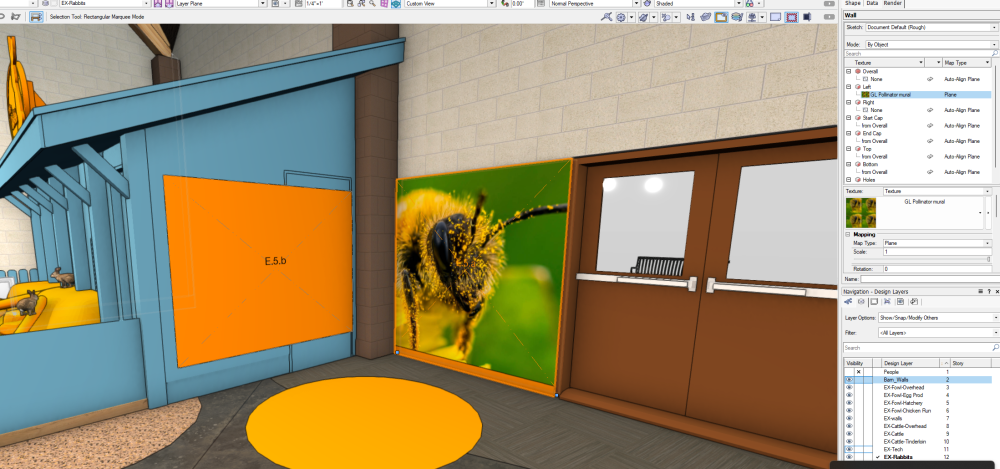
Hello all, I am using Data Visualizations to clarify who is responsible for different scopes of work on a project. Everything is working well, except for Walls that have textures by face object. Form some reason these textures are not getting overwritten by the Visualization manager. Below, the blue walls are textured by Component and the Vis overrides the texture as expected. The wall with the Bee on it is a wall textured by Object with the LEFT parameter having texture. I believe the VIz manager should overwrite this texture too (It should be all orange like the exposed bit on the bottom). I can convert the Bee wall to being textured by component and/or add a thin extrude for the texture, so I have a workaround, but I think this is a bug, right? Bart
-
Realistic 3D human figures for renderings
BartHays replied to MGuilfoile's question in Troubleshooting
Well this is a tricky box to unpack but there is also DAZ 3D. Like Poser, DAZ is a tool for creating fantasy art of (mostly) human figures. Be wary there is a lot of content there that is marginally SFW. However, there is also a HUGE model repository. The model are much less expensive than at many other model houses. The DAZ 3D software is free. and you can export models and textures to OBJ files. The assets are where they make money. There are base figures for humans that are totally posable and there are many stock poses too. In my museum work I have used many of the Animals, plants, and props from DAZ and posed them to suit my needs. Humans are complicated enough that I have found there is better value in stock 3D figures like the ones above , or just Entourage silhouettes. But, if you want to take the deep dive, its another resource. www.daz3d.com Bart -
I'm not a MacOS user but I have seen the Vision library error, Typically a machine reboot solves the problem. Second step: rename your preferences folder and let VW recreate the preferences. Third Step, contact your VW vendor for Technical support. Bart