Jesse Cogswell
-
Posts
634 -
Joined
-
Last visited
Content Type
Profiles
Forums
Events
Articles
Marionette
Store
Everything posted by Jesse Cogswell
-
Quite right that the Control Point is going to be based off of the PIO insertion point, and you did exactly the right thing to compensate for that. As a gentle warning, also make sure that your plug-in still works if the user origin doesn't match the internal origin. Nearly every VS function references the internal origin, so things can get screwy especially if you're using a plug-in that's saving coordinates into a text field. In those cases, you will need to use GetOriginInDocUnits to pull the user origin to compensate.
-
@spettitt You should be able to do the control point solution without needing events, and it might be cleaner from a usability standpoint. You would just need to specify a control point parameter and then pull it using the standard PControlPoint01X and PControlPoint01Y like you would any other parameter value. If I can wrap up my immediate tasks this morning, I can fab up a Vectorscript example for you.
-
This post from 2023 might help you get started on a basic way of pulling your truss info using PickObject. The code is in Vectorscript but it is very basic and should be easily translated to Python: In terms of building associations like what you're looking for, the AddAssociation functions don't quite work the way you might want them to. At the moment, the only options you have is to delete or reset your object if the associated object is deleted. There's not currently a way to have a an associated PIO update itself if the associated object has been changed (such as trim height in your case), so I always add a "Refresh Object" button to the OIP or write a menu command to refresh all of the desired PIOs in the drawing. The good news is that AddAssociation does not require the PIO to be event enabled. The bad news is that if you want to add buttons to the OIP, the PIO must be event enabled. I wrote up something of a "basic" event enabled plug-in with everything commented in case you would like to learn event handling. @FranAJA even adapted some of the code into Python, so you might find it useful: If you wanted to keep your PIO simple, what you might consider doing is using PickObject similar to my example above to pull the UUID of the truss object, then having a boolean parameter called "Lock" that would disable the PickObject code and keep the PIO associated with whatever object it last picked up with PickObject. OR you could get fancy by using a Control Point parameter and have the PickObject use the Control Point to pull the handle, so that the label can be wherever and the invisible control point just needs to be in contact with the truss.
-
I just tried this in VW2023 and it worked as expected. Can you post a screenshot of the filter parameters?
-
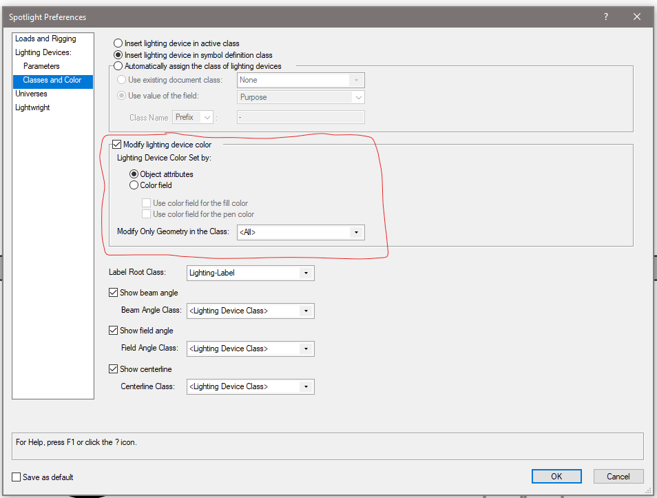
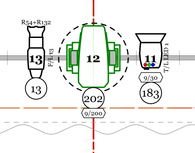
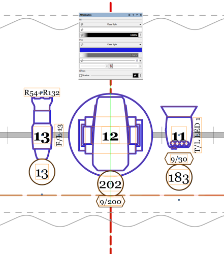
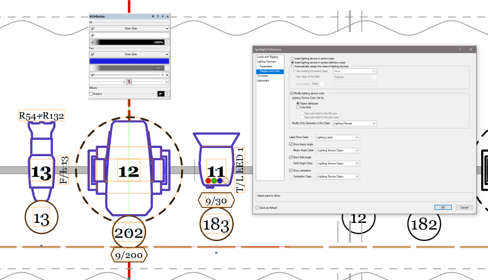
For lighting fixtures, there are a couple of different options you want to look into. These are document settings, so they will need to adjusted from drawing to drawing. They can be found under File - Document Settings - Spotlight Preferences. There is a tab within the Lighting Devices section called Classes and Color. These settings determine which classes new lights are placed in, and how color works for them. By default, Insert lighting devices in active class will be selected, so placing new fixtures will always appear in the currently active class. There is another option, called Insert lighting device in symbol definition class. This is my preferred method, and new fixtures would be placed based on the class specified in the Edit Symbol Options dialog for the symbol that defines the Lighting Device object. I prefer this because I can specify different fixture type be different classes if I so choose, and then I don't have to worry about what my currently active class while I'm plotting. So if I'm plotting out focus areas while I'm building my plot, I can leave my Focus Areas class active and know that my lights will always be in the classes I want them in. You can also have Vectorworks build classes for you based on a field parameter, such as color or device type by selecting the third option, Automatically assign the class of the lighting devices and choosing the options that you want. Now, onto how Lighting Device objects respond to Attributes. By default, Lighting Devices will only show the graphic attributes of the symbol geometry. This means that if you wanted some of the fixtures to be lined in blue and some in black, you would need two different symbols. However, if you check the box for Modify lighting device color, you will have a small bevy of options for how to handle the color. From the sound of it, you want to be sure to have Object attributes selected, where the lighting fixture will take on the values of the Attributes palette. But be aware that if you leave the Modify Only Geometry in the Class option set to <All>, this will affect all of the geometry of the fixture, which can lay havoc with things like moving light radius circles. Example of lighting fixtures based on symbol geometry: Same fixtures after selecting Modify Color - Object Attributes This means that if you want things to not be affected by this change, you would need to have elements of the symbol classed out so that it would only affect the desired geometry. Same example but with the Modify Only Geometry value set to my Lighting-Fixtures class You also have options to use the fixture's color field to set either the fill or pen of the fixture. One other place to look for something like this is using the Data Visualization tools. I can't help you too much with them, as they're not currently part of my workflow and I've only messed around with them a little bit, but there are some users of this forum doing some pretty amazing things to adjust things on a viewport by viewport basis.
-
They made a couple of changes to icons in VW2024. One of them was moving away from the .png file format and instead going to .svg format. This is great because .svg format is actually a vector graphic, so the icon will scale appropriately between standard density and high density displays. They also added dark mode to WIndows systems, which is what is causing your red X issue. If you want to continue using the .png method, you will need four separate files per icon: Icon.png (26x20 pixels at 72 dpi) Icon @2x.png (52x40 pixels at 72 dpi) Icon_dark.png (26x20 pixels at 72 dpi with colors set for dark mode) Icon_dark @2x.png (52x40 pixels at 72 dpi with colors set for dark mode) VW will determine the pixel density of the display and will choose which icon to display. Even though it shouldn't really matter since you're specifying the exact pixel sizes, Mac requires that you must have a dpi of 72 for your icons otherwise they will error out. I've never had a problem on Windows, but if you will have some Mac users, it's best to plan for it. The key here is having icons with the _dark suffix, that is what VW will use when you have dark mode engaged. I'm betting that if you were to switch to light mode, your icon would work properly. Now, if you want to embrace the future and use the .svg format, you only need two icons: Icon.svg Icon_dark.svg Since the icons are scalable vector graphics (that's where the svg comes from), VW will automatically scale the icon to match the display dpi. But something to consider is that those icons will not work on versions of Vectorworks before 2024, so if backwards compatibility is important to you, you might want to stick with the .png method. That said, if you're developing plug-ins in VW2024, they wouldn't be compatible with earlier versions anyway so it would probably be best to embrace the newer and better format. In terms of how to create the icons, here's a couple of rough work flows you could try. .png method: I use the .png method since backwards compatibility is important to me and some users of my plug-ins. I'll generally draft up the icon in Vectorworks (since it's the drawing tool I'm most comfortable with anyway), then make sure everything has a pretty thick line weight. I'll then zoom out until the icon is roughly the size it will be in the workspace. I take a snip of the screen using the Windows snipping tool, and paste it into Photoshop. In Photoshop, I'll delete the background behind the icon using the magic wand tool, and then use the crop tool with the settings set to 52x40 pixels at 72 dpi. If the output is to my liking, I'll save this as the @x2.png file and then scale that again for the standard 26x20 icon. The real trick is managing any kind of aliasing that happens when the image is "de-rezed", hence why I tend to use really thick line weights. .svg method: Once again, I'll draft out my icon in Vectorworks. From there, I will export it as an .eps file using the File-Export-Export EPSF option. This will give me a vector graphic that I can manipulate in Adobe Illustrator. I'll import the .eps file in Illustrator, and make sure that I set my artboard to be 26x20 pixels. I'll manipulate the icon so it fits within the artboard, then export it as .svg. I'll then make adjustments to color for the dark mode options (such as inverting black to white) and export the _dark.svg file. I recognize that both of my methods require the use of Adobe software. You could try using something like Inkscape instead of Illustrator, which is free, but also does not accept .eps files for import. In this case, you could try exporting from VW as a .dxf file, which Inkscape will accept.
-

Multi-column Layout
Jesse Cogswell replied to NealP's question in Wishlist - Feature and Content Requests
@BartHays The column spacing is only in regard to newly created text boxes. Once created, their location will be entirely independent. If you want to quickly change the spacing, delete all of the created children and change the column value, which will force a reset and redraw. I can think of a couple of ways to have a text box's location be tied to the master's until it's been moved manually. I'll put it on the revision list for when I get time. As for the other issue, I'll see what I can do. So that the settings copy over, the new text box is created inside the PIO container of the original before it is moved to the layer. There's a fantastic chance that I was lazy when I coded it and just used the master's UUID to set the parent layer rather than the text box that would be overflowing. If that makes sense. I'll look at it once I finish filing my taxes. -
Multi-column Layout
Jesse Cogswell replied to NealP's question in Wishlist - Feature and Content Requests
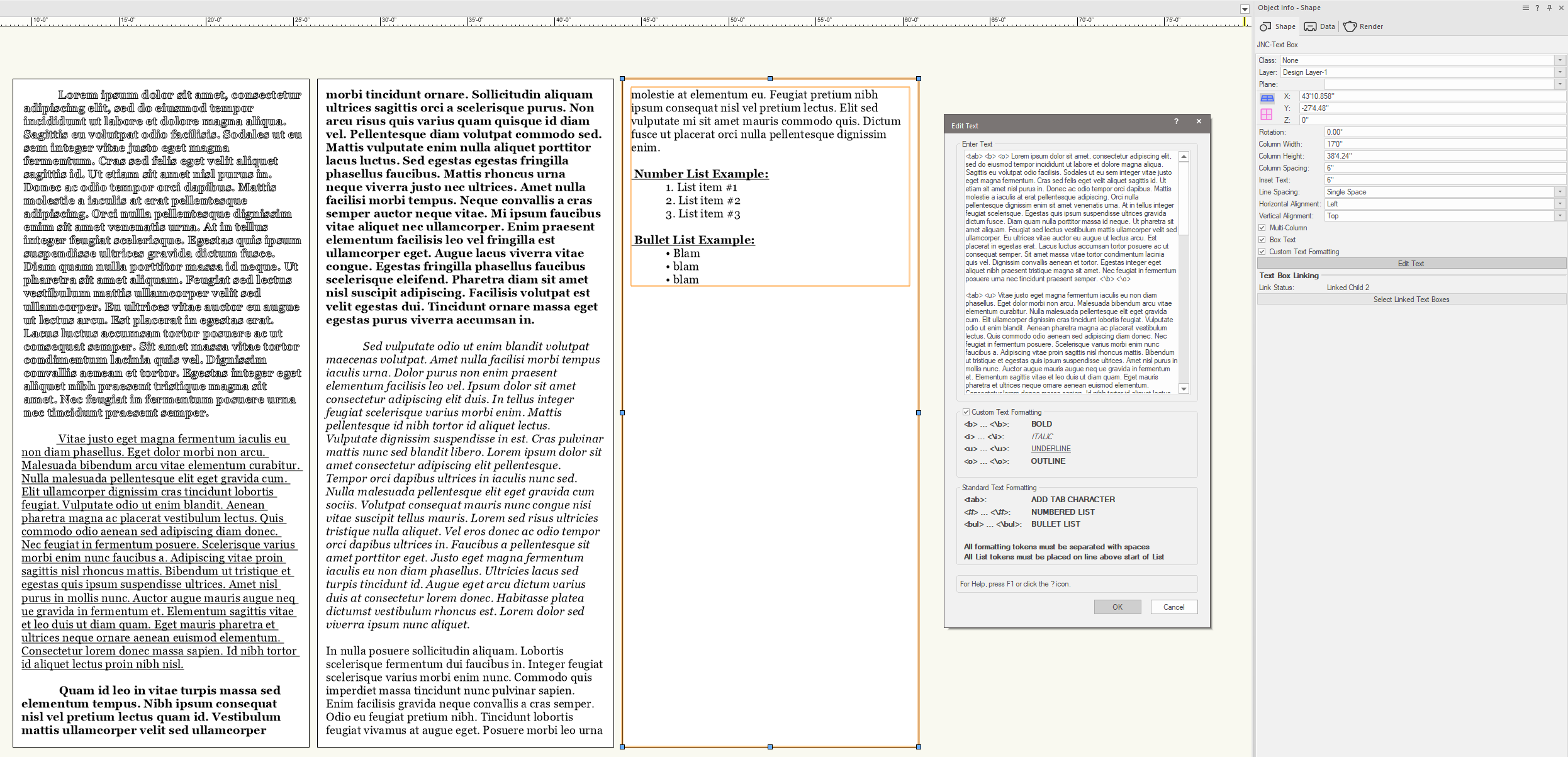
And if you want to use my example text from above for your own testing, it is pasted below: <tab> <b> <o> Lorem ipsum dolor sit amet, consectetur adipiscing elit, sed do eiusmod tempor incididunt ut labore et dolore magna aliqua. Sagittis eu volutpat odio facilisis. Sodales ut eu sem integer vitae justo eget magna fermentum. Cras sed felis eget velit aliquet sagittis id. Ut etiam sit amet nisl purus in. Donec ac odio tempor orci dapibus. Mattis molestie a iaculis at erat pellentesque adipiscing. Orci nulla pellentesque dignissim enim sit amet venenatis urna. At in tellus integer feugiat scelerisque. Egestas quis ipsum suspendisse ultrices gravida dictum fusce. Diam quam nulla porttitor massa id neque. Ut pharetra sit amet aliquam. Feugiat sed lectus vestibulum mattis ullamcorper velit sed ullamcorper. Eu ultrices vitae auctor eu augue ut lectus arcu. Est placerat in egestas erat. Lacus luctus accumsan tortor posuere ac ut consequat semper. Sit amet massa vitae tortor condimentum lacinia quis vel. Dignissim convallis aenean et tortor. Egestas integer eget aliquet nibh praesent tristique magna sit amet. Nec feugiat in fermentum posuere urna nec tincidunt praesent semper. <\b> <\o> <tab> <u> Vitae justo eget magna fermentum iaculis eu non diam phasellus. Eget dolor morbi non arcu. Malesuada bibendum arcu vitae elementum curabitur. Nulla malesuada pellentesque elit eget gravida cum. Elit ullamcorper dignissim cras tincidunt lobortis feugiat. Vulputate odio ut enim blandit. Aenean pharetra magna ac placerat vestibulum lectus. Quis commodo odio aenean sed adipiscing diam donec. Nec feugiat in fermentum posuere. Scelerisque varius morbi enim nunc faucibus a. Adipiscing vitae proin sagittis nisl rhoncus mattis. Bibendum ut tristique et egestas quis ipsum suspendisse ultrices. Amet nisl purus in mollis nunc. Auctor augue mauris augue neq ue gravida in fermentum et. Elementum sagittis vitae et leo duis ut diam quam. Eget mauris pharetra et ultrices neque ornare aenean euismod elementum. Consectetur lorem donec massa sapien. Id nibh tortor id aliquet lectus proin nibh nisl. <\u> <tab> <b> Quam id leo in vitae turpis massa sed elementum tempus. Nibh ipsum consequat nisl vel pretium lectus quam id. Vestibulum mattis ullamcorper velit sed ullamcorper morbi tincidunt ornare. Sollicitudin aliquam ultrices sagittis orci a scelerisque purus. Non arcu risus quis varius quam quisque id diam vel. Pellentesque diam volutpat commodo sed. Mattis vulputate enim nulla aliquet porttitor lacus luctus. Sed egestas egestas fringilla phasellus faucibus. Mattis rhoncus urna neque viverra justo nec ultrices. Amet nulla facilisi morbi tempus. Neque convallis a cras semper auctor neque vitae. Mi ipsum faucibus vitae aliquet nec ullamcorper. Enim praesent elementum facilisis leo vel fringilla est ullamcorper eget. Augue lacus viverra vitae congue. Egestas fringilla phasellus faucibus scelerisque eleifend. Pharetra diam sit amet nisl suscipit adipiscing. Facilisis volutpat est velit egestas dui. Tincidunt ornare massa eget egestas purus viverra accumsan in. <\b> <tab> <i> Sed vulputate odio ut enim blandit volutpat maecenas volutpat. Amet nulla facilisi morbi tempus iaculis urna. Dolor purus non enim praesent elementum facilisis leo vel. Ipsum dolor sit amet consectetur adipiscing elit duis. In tellus integer feugiat scelerisque varius morbi enim. Mattis pellentesque id nibh tortor id aliquet lectus. Vulputate dignissim suspendisse in est. Cras pulvinar mattis nunc sed blandit libero. Lorem ipsum dolor sit amet consectetur adipiscing elit pellentesque. Tempor orci dapibus ultrices in iaculis nunc sed. Nulla malesuada pellentesque elit eget gravida cum sociis. Volutpat consequat mauris nunc congue nisi vitae suscipit tellus mauris. Lorem sed risus ultricies tristique nulla aliquet. Vel eros donec ac odio tempor orci dapibus ultrices in. Faucibus a pellentesque sit amet porttitor eget. Justo eget magna fermentum iaculis eu non diam phasellus. Ultricies lacus sed turpis tincidunt id. Augue eget arcu dictum varius duis at consectetur lorem donec. Habitasse platea dictumst vestibulum rhoncus est. Lorem dolor sed viverra ipsum nunc aliquet. <\i> In nulla posuere sollicitudin aliquam. Lobortis scelerisque fermentum dui faucibus in. Integer feugiat scelerisque varius morbi enim nunc. Commodo quis imperdiet massa tincidunt nunc pulvinar sapien. Enim facilisis gravida neque convallis a cras semper. Odio eu feugiat pretium nibh. Tincidunt lobortis feugiat vivamus at augue eget. Posuere morbi leo urna molestie at elementum eu. Feugiat pretium nibh ipsum consequat nisl vel pretium lectus. Elit sed vulputate mi sit amet mauris commodo quis. Dictum fusce ut placerat orci nulla pellentesque dignissim enim. <b> <u> Number List Example: <\b> <\u> <#> List item #1 List item #2 List item #3 <\#> <b> <u> Bullet List Example: <\b> <\u> <bul> blam blam blam <\bul> -
Multi-column Layout
Jesse Cogswell replied to NealP's question in Wishlist - Feature and Content Requests
Good morning, friends. I have been working on this off and on for the last couple of weeks and have come up with a plug-in that should do most of what you need. It's a little hacky and has a couple of rules / caveats, but it's worth a try. The plug-in is generally a Rectangle Object PIO that has an attached text string. You have options in terms whether the text is "boxed", whether the text is inset from the box edge, the line spacing, and the horizontal and vertical alignment. The font and text size is set using the Text menu while the object is selected. It will also use the Font Style applied to all of the text. The text can be edited by either double-clicking the box or by clicking the Edit Text button in the OIP. Now for the fun stuff. There's a checkbox in the OIP called Multi-Column. When this option is not checked, the text box will automatically resize based on the text contained in it, expanding and contracting as necessary. When this option is checked and the text box is resized, any "overflow" text will be placed in a new text box, created using the same settings as the original. Once this text box is created, it will be linked to the master and can be individually positioned and resized. If you double-click or click Edit Text on any linked text box, the dialog will be populated with the text of the master. Deleting a "master" text box will also delete any linked children, or if you select a child and uncheck Multi-Column, any children downstream will be deleted and the selected text box will be resized to fit the text. If you select a master and uncheck Multi-Column, it will resize the text box and delete linked children. If you resize a text box and cause the downstream text boxes to be empty, they will maintain their link but just be empty. You are free to delete children as necessary. If you delete a child in the middle of a chain, the next time the text box preceding the deleted one will generate a new text box with matching settings. If a text box is in a linked chain, there will be a button in the OIP called Select Linked Text Boxes, which will select all text boxes in the link chain. If a text box is not part of a linked chain, the button will instead say Link Text Box. When you click on this button, you will be asked to select another text box. Once you click another text box, the original text box will be put in the same chain as the box you clicked, added to the end of the chain. The fun bit is a checkbox in the OIP called Custom Text Formatting. If this box is checked, text can be formatted using formatting tokens similar to HTML: <b> ... <\b>: Any text between the tokens will be bold. <i> ... <\i>: Any text between the tokens will be italic. <u> ... <\u>: Any text between the tokens will be underlined. <o> ... <\o>: Any text between the tokens will be outlined. If you use these options, you must have the PIO's Text - Font Style option set to Plain Text. Otherwise you'll get some pretty bonkers formatting. There are a couple of other formatting tokens that you should know about: <tab>: This will place a tab character in the text. <#> ... <\#>: Any lines of text between the tokens will be formatted as a numbered list. <bul> ... <\bul>: Any lines of text between the tokens will be formatted as a bulleted list. The numbered and bulleted list can only go one level deep. Now, here are the rules: The code uses spaces to parse the text. This means that all of the formatting tokens need a space on either side (unless it's the end of a line, then it doesn't need a space after the token). Unfortunately, if you have a double space, the code will see this as the end of the text and will not populate anything afterward. This means that if you learned to double space after each sentence, you will have to fight that urge. The code also parses lines of text using the carriage return character. If you want to have an empty line between paragraphs, you will need to put a space in the empty line, otherwise the plug-in will see the empty line as the end of the text. For the list formatting tokens, the start token must be placed as part of the line before the list starts, not at the start of the list. Otherwise the code will miss the first line in the list. Don't select multiple text boxes in the same link chain and uncheck Multi-Column unless you want to crash Vectorworks. This plug-in can get pretty slow with very long strings of text. This is because it has to essentially add a word at a time to the text box, then check to see if the text box has exceeded the Column Height parameter to determine if it needs to overflow, as well as check word by word for formatting tokens. If you have a lot of text in a text box or chain, be patient. Unchecking the Multi-Column box resulting in deleting downstream children can sometimes leave a "ghost" of the deleted text boxes. Move your view by either panning the drawing or zooming in or out to get these ghosts to clear. If you are losing empty lines, look at where your formatting tokens are (especially if they are at the front of a line), try moving them to the end of the line above instead. Don't use tabs within numbered or bulleted lists. Don't get them wet. Don't feed them after midnight. To install the plug-in, follow the steps below: Download the attached JNC-Text Box.zip file, but do not extract it. In Vectorworks, go to Tools - Plug-ins - Plug-in Manager. Click on the Third-party plug-ins tab. Click on the Install button. Navigate to the downloaded .zip file. Restart Vectorworks. Once relaunched, go to Tools - Workspaces - Edit Current Workspace. Select the Tools tab. In the box on the left, find and expand the category called JNC. In the box on the right, find a toolset to place the tool in, such as Dims/Notes or Basic. Click and drag the Create JNC-Text Box tool from the box on the left to the desired toolset in the box on the right. Press OK to reset your workspace. The plug-in will work with any version of Vectorworks 2019 or newer. Have fun and let me know if anything breaks or if you have any suggestions for improvements (but be patient, this isn't my full-time, or even part-time job). JNC-Text Box.zip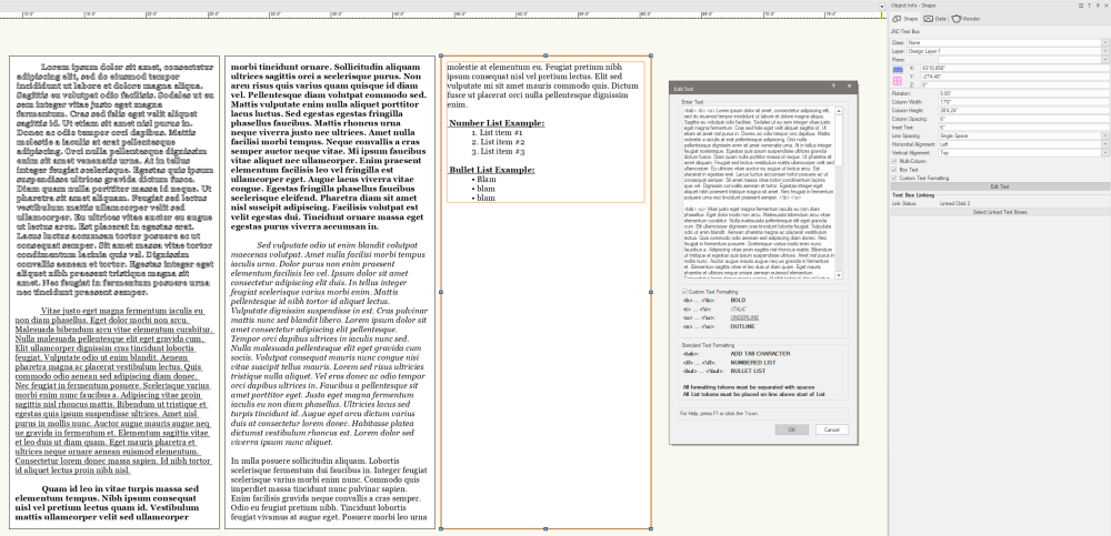
-
There's a Vectorscript function that will return the number of classes in the active drawing: ClassNum. You could make a document script, something to the tune of AlrtDialog(Num2Str(0,ClassNum)); that will spit out the number.
-
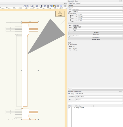
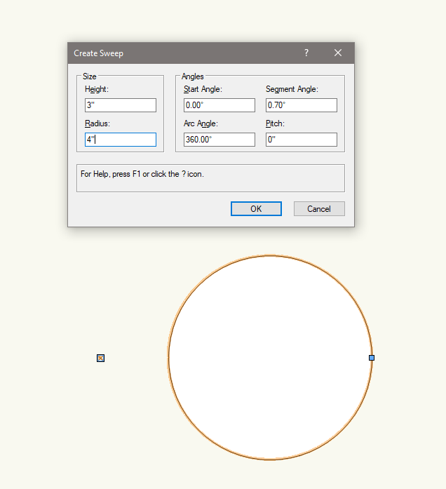
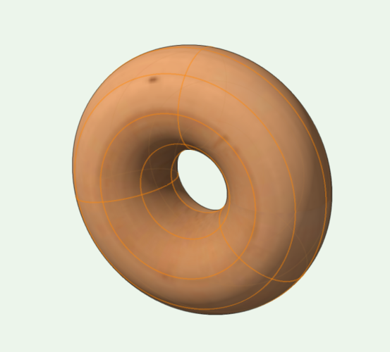
Oh, and as a general note for sweeps, in an ideal world, you want to sweep a single object, not a collection of objects. In your case, you could grab all of your shapes and run a Modify-Add Surface command before doing the sweep. You'll get the same end shape, but it uses far less computational power to make it. I once received a drawing that would crash when trying to update a Section Viewport. The drawing contained 150 track head lighting fixtures whose 3D components contained a sweep that was made up with a dozen or so rectangles and arcs rather than a single polyline. If there were only a couple in the drawing, the section was fine, but with 150 of them, the drawing would crash. I grabbed all of the shapes in the sweep profile and added them, the section (and the drawing performance in general) was much happier.
-
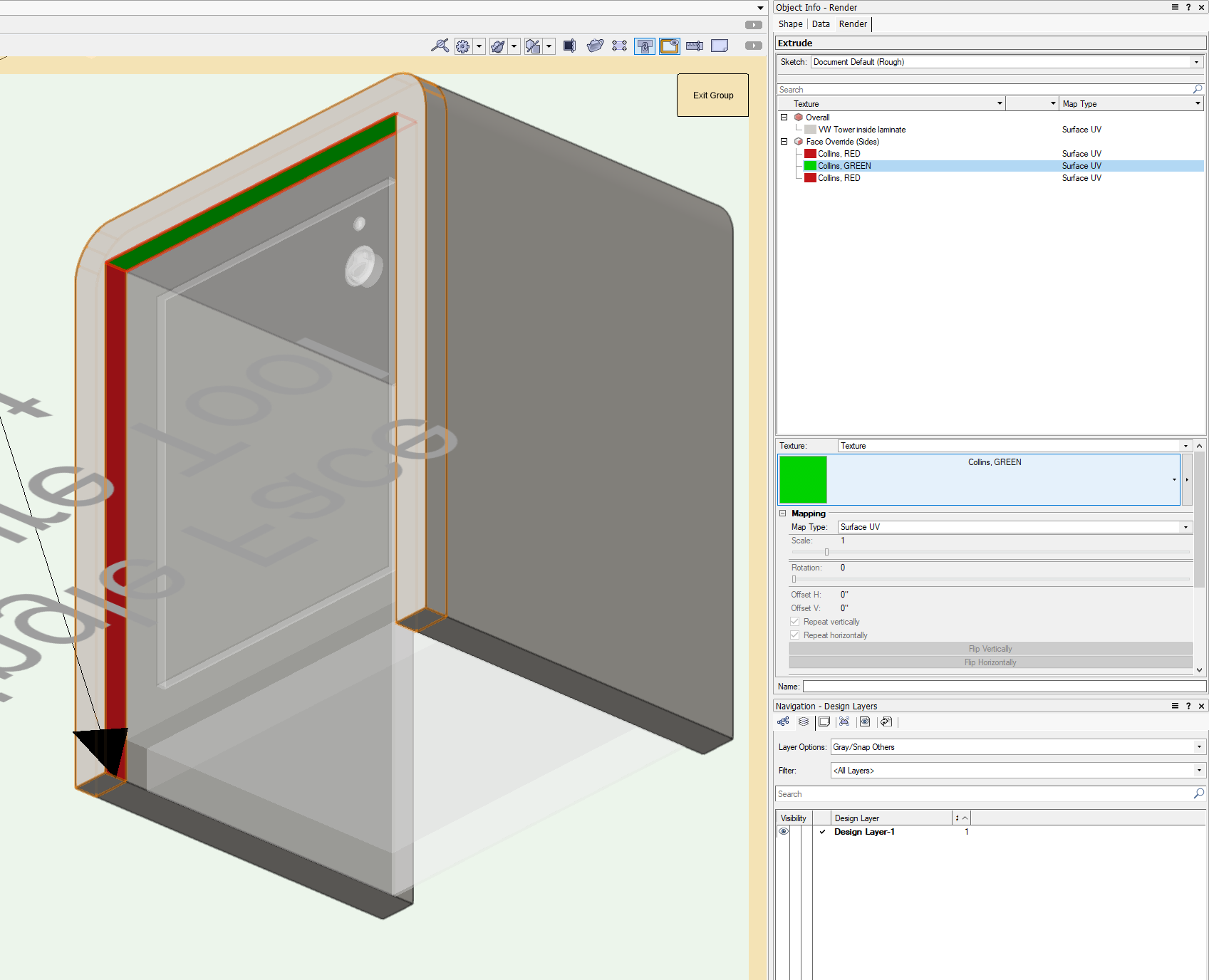
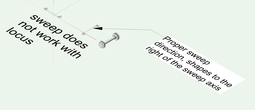
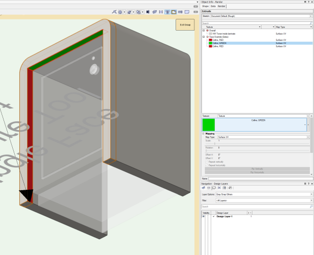
The sweep issue happens because you are setting your axis in the wrong direction. All sweeps must be set up with shapes to the right of the sweep axis. If I understand your shape correctly, you don't even need a locus point. As for the texturing issue, there's something weird with your extrudes. As I think @Bart Hays mentioned to you in your other post, your extrudes are behaving in the pre-VW2021 way of having the extrude sides acting as a single face. When I recreated your extrude shape by copying and pasting the profile and re-extruding it, the per face texture tool works as planned. EDIT: Shoot, @Tom W. beat me to it! Question, broken Sweep and Single Face Texture Tools JNC.vwx
-
There isn't one native to Vectorworks, but it's possible to create one using a script. PROCEDURE SelectNextFixture; {* Selects next Lighting Fixture on position Developed by: Jesse Cogswell Date: 4/10/2024 Revisions: *} CONST kRec = 'Lighting Device'; VAR position,nextUnit:STRING; unitNum:INTEGER; h:HANDLE; BEGIN h:=FSActLayer; IF(GetName(GetParametricRecord(h)) = kRec) THEN BEGIN position:=GetRField(h,kRec,'Position'); unitNum:=Str2Num(GetRField(h,kRec,'Unit Number')); nextUnit:=Num2Str(0,unitNum + 1); DSelectObj(ALL); ForEachObject(SetSelect,((R IN [kRec]) & (kRec.'Position' = position) & (kRec.'Unit Number' = nextUnit))); END; END; Run(SelectNextFixture); To get this to be a key combination, follow the steps below: Go to Tools - Plug-ins - Plug-in Manager Click on the New button Make sure Command is selected and give the command a name, like Select Next Fixture Click on the Edit Script button Make sure the Language drop-down is set to VectorScript Copy and paste the code above into the editor Press OK to close the editor Press OK to close the Plug-in Manager Go to Tools - Workspaces - Edit Current Workspace Click on the Menus tab In the box on the left, find and expand the Miscellaneous category In the box on the right, find a menu to put your new command in, such as Spotlight When you have the command selected, you can specify a keyboard shortcut in the lower right of the dialog box Press OK to close the Workspace Editor You should be able to assign a shortcut even if the command is not in one of your workspace menus, so if you don't want to clutter up your Spotlight menu, you might not need to put the command in there.
- 1 reply
-
- 3
-

-
Can you show what dialog box pops up telling you that you can't use a locus point or what the shape you are trying to sweep looks like? I'm drafting on VW2023 right now and can use a locus to set the center of the sweep.
-
You have a couple of options. You can use AddSurface and feed in the two polys as in polyOut := AddSurface(poly1,poly2), which will result in a final polyline object, or you can use DoMenuTextByName('Compose',0) on the selection to force a compose command, resulting in a polygon object.
-
I don't think @DCarpenter is worried about moving the extrude in space, but is more trying to change the height of the extrude itself. What you want to use is Get3DInfo to get the depth of the first extrude, then use Set3DInfo to change the depth of the duplicated extrude. There's even an example script that does exactly what @DCarpenter is looking for on the wiki page for Get3DInfo.
-
Request: Make 2d/3D Symbol 'Unique' script
Jesse Cogswell replied to MarcelP102's topic in Vectorscript
After some further testing, this doesn't appear to work with flipped instances of symbols on a Sheet Layer, but works correctly on a Design Layer. I'm currently chalking this up to some oddness with the Mirror function, which may be fixed with the newer MirrorN function added to VW2023. Further testing required. -
Request: Make 2d/3D Symbol 'Unique' script
Jesse Cogswell replied to MarcelP102's topic in Vectorscript
Hmm, I'll need a little more time to investigate the issues that @MarcelP102 mentioned above (I must have been busy when he made the post all those years ago, I don't remember seeing those bugs), but I was able to fix the issue with the internal origin. To compensate for the internal origin, you need to use GetOriginInDocUnits to pull the current User Origin, then subtract those values from the placement or movement script. I had actually done that in the origin version of this script, but rather than applying those values directly to the Symbol call, I instead applied them to the Move3DObj call that moved the newly placed "unique" symbol to match the height of the original object. This works great for objects on Design Layers, but doesn't seem to work with objects on Sheet Layers. I moved added the user origin adjustment to the Symbol call and it seems to work properly. I'll give @MarcelP102's issue a look. I suspect the flip problems arise from having flipped symbols nested inside the symbol you are trying to make unique. The script does do a flip check, but only on the original base symbol instance, not on any nested symbols. Make Symbol Unique.vsm -
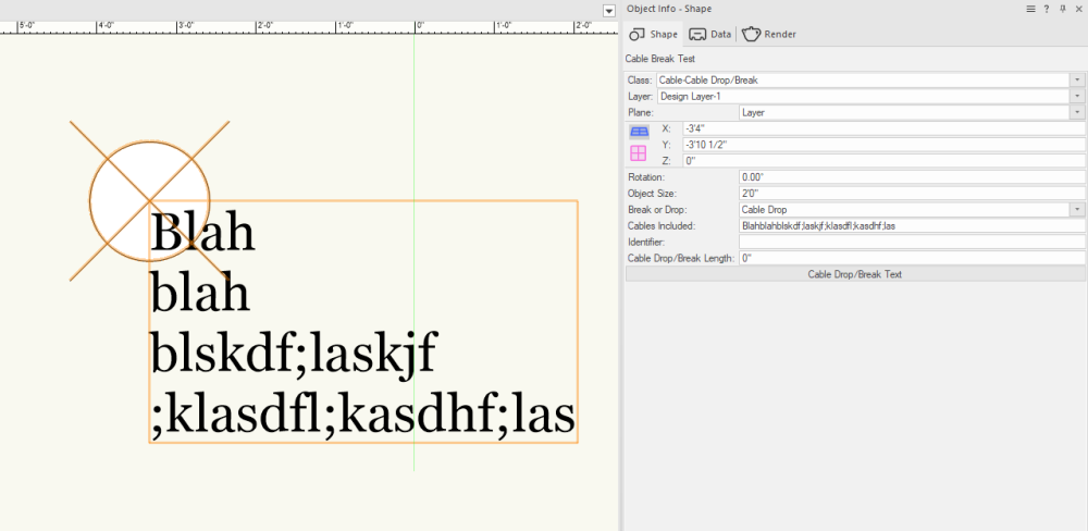
The code is working properly as far as I can tell. When you press OK on the dialog box, the CableTextDT is updating properly, as seen in the OIP. Your kResetEventID code currently isn't doing anything with the data (stored in the text variable). If you want the text displayed, you will need to add a line to the tune of: IF (text <> '') THEN CreateText(text); Handles were undoubtedly the hardest concept for me to wrap my head around. All of my coding experience before Vectorscript was with object-oriented languages (Java and Python). With an OO language, you would define an object and all needed subroutines (such as get/set commands) as methods. Once an object is defined, you could assign it to a variable. As an example, you could have something like rect1 = Rectangle(<width>,<height>). The variable rect1 is now defined as a Rectangle object. So if you wanted to get the width again for some computation, you would use width = rect1.GetWidth(). Because Vectorscript / Pascal is not object-oriented, you instead use handles as a way to assign objects to variables. Most of the time in VS, you need to create the object first, then use something like LNewObj to store the object's handle into a variable for use later. If you are immediately making changes to an object (such as formatting your text in the above example), you don't need to store the object in a handle because you can keep using LNewObj until you create another object. But if you need to access the text later in the code, it is best to store it as a handle. One thing to watch out for when using LNewObj on text objects is that if the text object is empty, it won't return a handle. So any formatting you try to do on an empty text object will instead affect the object created before the text. So I always use an IF statement to test the string to make sure it's not empty before creating and formatting a text object. One of the most important handles when making Plug-in Objects is the currently executing plug-in's handle (named objHd in my code) since that's what you use to update the parameters such as your CableTextDT parameter using SetRField. To get the handle, you use GetCustomObjectInfo to return the name of the PIO (objName, Cable Break Test in your example), the handle of the current PIO object (objHd), a handle to the parametric record (recHd), and the wall the PIO is inserted in (wallHd for PIOs that can be inserted in walls). This function returns a boolean (TRUE if successful), so I usually combine it with a SetObjectVariableBoolean(objHd, 800, TRUE) which enables all text in the PIO to inherit from the Text menu of the PIO object itself. As for event enabled plug-ins, I have an example object that has all of the necessary code commented out so that you can see what it is doing and why it is needed. Have a look if you want a better understanding of how to handle event enabled plug-ins, so that you can add things like double-click behavior and collapsing sections of the Object Info Palette:
-
For anyone who stumbles on this topic in the future, I wrote a menu command that will do this, detailed here:
-
Linking Record formats to referenced Excel worksheets
Jesse Cogswell replied to Tim Harland's topic in General Discussion
I watched the Vectorworks University video and, no offense to Vectorworks, but big yikes! Sometimes I wonder if they think we get paid by the click. @Maury Jensen contacted me earlier this week about this topic, and I sat down and wrote him a menu command to do this. The menu command launches a dialog box letting you choose a Worksheet, a Record to link it to, and a Field to use as a key. When you press OK, it will go through the chosen Worksheet line by line and scour the drawing for objects that have the chosen Record attached with a matching key. When it finds one, it will go through the Record Fields and pull the data from the Worksheet with the matching key, then reset the object. The tool also runs a "Deselect All" command when you press OK, and will select any affected object, so upon completion, you should be able to easily tell which objects have been updated. The tool requires the Worksheet to have a header row with the columns matching exactly the Record Field names, so be careful about extra spaces and capitalization. It will do some basic error checking for you, when you select a Worksheet or Record, it will compare the first row of the Worksheet and the Record Field names. If any Record Field does not have a matching column, the Status will change to Column Name / Record Field Mismatch and the Check Mismatch button will be enabled. If you click the button, it will pop up an alert for each missing Record Field. That said, the tool won't stop you from clicking OK when there's a mismatch, so if you have extra Record Fields that you don't want on the Worksheet, you can. It will also save your choices, so if you run the command again, it will have the Worksheet, Record, and Key Field will be pre-selected, so it's very quick to update as your Worksheet is updated. For Maury's test case, he used a Worksheet that was referencing an external Excel document. One huge advantage of this system over the one highlighted in the Vectorworks University video is that this also maintains the Excel file rather than having to shuttle a CSV file between Excel and SQ Lite, so it's a little easier to maintain as Excel is a bit friendlier than an SQL database. To install this plug-in, follow the steps below: Download the attached Link Worksheet to Record.zip file, but do not extract it. In Vectorworks, go to Tools - Plug-ins - Plug-in Manager. Click on the Third-party plug-ins tab. Click on the Install button. Navigate to the downloaded .zip file. Restart Vectorworks. Once restarted, you will need to add the plug-in to your Workspace. Go to Tools - Workspaces - Edit Current Workspace. In the Workspace Editor, click on the Menus tab. In the box on the left, find and expand the JNC category. In the box on the right, find a menu where you'd like to have the command, such as Tools. Click and drag the Link Worksheet to Record command from the box on the left to the desired menu in the box on the right. Click OK to confirm and rebuild your Workspace. The plug-in should work with all versions of Vectorworks from 2019 or newer. Please let me know if anything breaks. Link Worksheet to Record.zip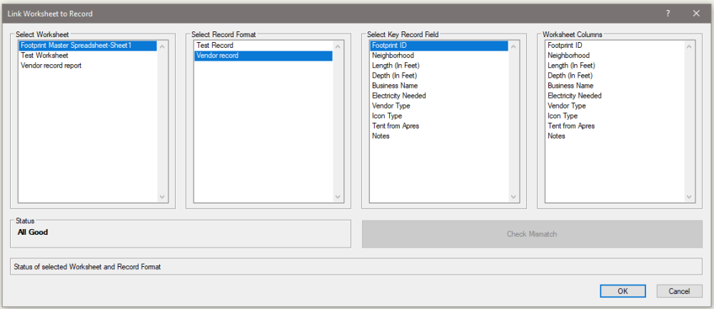
-
Extensive Patch List: Creating a Two-Page Worksheet Table
Jesse Cogswell replied to Cristiano Alves's topic in Entertainment
I wrote a plug-in to split Worksheets into smaller chunks. If you use it on a non-database worksheet, it will build references in to the "master" worksheet, so as you update the master, the splits will update after being recalculated. I'm guessing that your patch sheet was built using database rows, which can't be referenced in that way. My plug-in will instead make "absolute" copies of the database. This means that the split Worksheets will not reference the master, but my plug-in compensates for that by having an option to quickly overwrite any split Worksheets if they already exist in the drawing. These updates will carry across to any of the Worksheets currently placed on a Design or Sheet layer. Installation instructions are included in the post as well. -
I love my Zenbook Pro Duo. I was interested ever since Asus showed off the original one with the non-hinged bottom screen. When my Surface Book 2 was finally no longer powerful enough for what I needed and was looking at upgrades, the Asus was the same price as a Surface Book 3 and was much more powerful, so I pulled the trigger. Always having a second display handy is life changing. 90% of the time, I just have Notepad++ running on it, keeping track of all of the notes I have on my various projects. But I also do a fair bit of lighting console programming, and the second screen has been great for placing direct selects (basically extra buttons for things like macros, groups, and color palettes). I have never tried to move Vectorworks palettes down onto it. Vectorworks gets really cranky if you move palettes around to monitors with different scale factors and/or resolutions, so I can only imagine the trouble it's giving you. I do all of my drafting on a big 42" 4K monitor scaled at 100%, so the VW interface doesn't get in the way of anything and I don't feel the need to move palettes outside of the VW application window. But I just did a little test with VW2023 and was able to move palettes down, but I wasn't able to place them near the top of the bottom display without the title bar snapping up to the bottom of the top display.

-
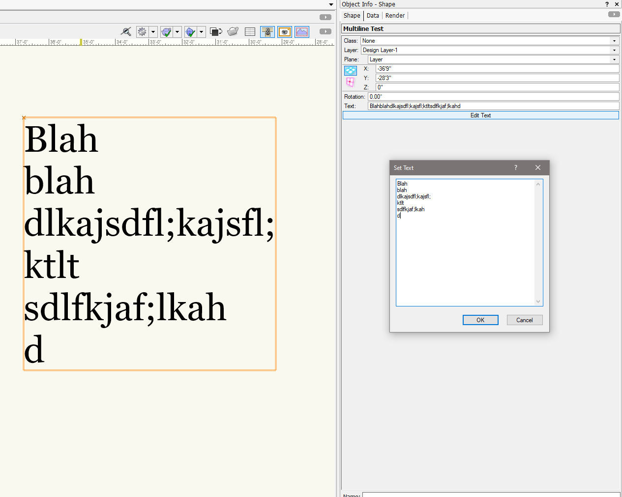
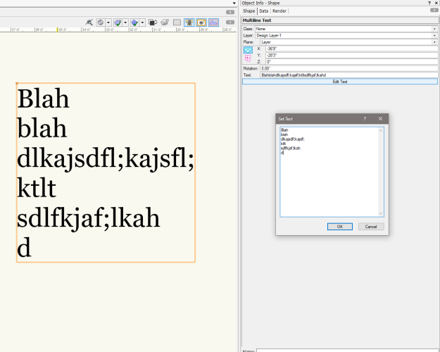
@Marc Powell What do you know about Event Enabled plug-ins? I was able to fab up this quick example of what you might be looking for. When you press the button, it opens a dialog box with a multi-line text box. When you press OK, it passes the contents of that box back to the PIO's parameter using a combination of GetMultilineText and ResetObject. I'm attaching the plug-in itself and have the code pasted below (don't judge, I wrote it in maybe 10 minutes so nothing is annotated). It is a Point PIO with a single parameter, called "text" and is set to Event-Enabled. PROCEDURE MultilineTest; CONST kResetEventID = 3; kObjXPropHasUIOverride = 8; kWidgetButton = 12; kObjOnInitXProperties = 5; kObjOnObjectUIButtonHit = 35; kButton1ID = 3000; kFontEnabled = 800; VAR objName:STRING; objHd,recHd,wallHd:HANDLE; text:STRING; theEvent,theButton,dialog,layoutDialog:LONGINT; result:BOOLEAN; FUNCTION DrawDialog(DName:STRING) : LONGINT; CONST kTextWidth = 50; kTextHeight = 20; VAR dia:LONGINT; BEGIN dia:=CreateLayout(DName,FALSE,'OK','Cancel'); CreateEditTextBox(dia,11,'',kTextWidth,kTextHeight); SetFirstLayoutItem(dia,11); DrawDialog:=dia; END; PROCEDURE DialogHandler(VAR item,data:LONGINT); BEGIN CASE item OF SetupDialogC: BEGIN IF(text <> '') THEN SetItemText(dialog,11,text); END; 1: BEGIN GetMultilineText(dialog,11,text); SetRField(objHd,GetName(recHd),'text',text); ResetObject(objHd); END; 2: BEGIN END; END; END; BEGIN text:=Ptext; IF GetCustomObjectInfo(objName,objHd,recHd,wallHd) THEN SetObjectVariableBoolean(objHd,kFontEnabled,TRUE); vsoGetEventInfo(theEvent,theButton); CASE theEvent OF kObjOnInitXProperties: BEGIN result:=SetObjPropVS(kObjXPropHasUIOverride,TRUE); result:=SetObjPropVS(kWidgetButton,TRUE); result:=vsoInsertAllParams; result:=vsoAppendWidget(kWidgetButton,kButton1ID,'Edit Text',0); END; kObjOnObjectUIButtonHit: BEGIN CASE theButton OF kButton1ID: BEGIN dialog:=DrawDialog('Set Text'); layoutDialog:=RunLayoutDialog(dialog,DialogHandler); END; END; END; kResetEventID: BEGIN Locus(0,0); IF(text <> '') THEN CreateText(text); END; END; END; Run(MultilineTest); The plug-in object attached to this message can be found in the Research and Development category of the Workspace Editor and will work on any version of Vectorworks 2019 or newer. Multiline Test.vso
-
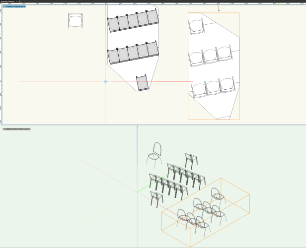
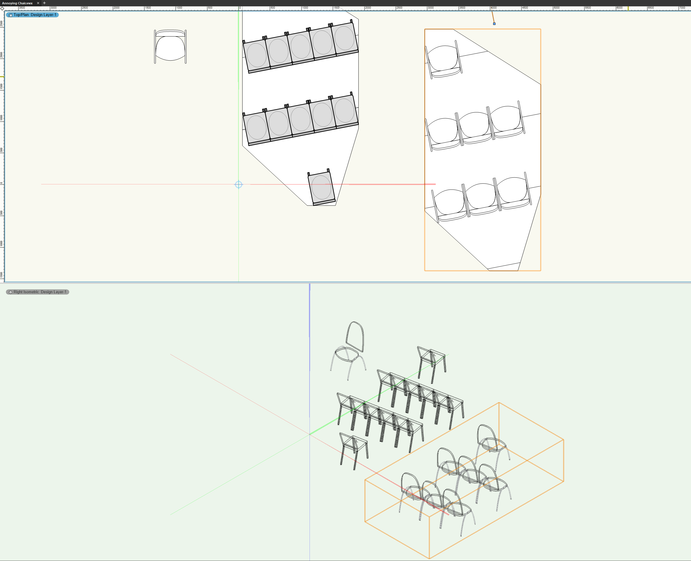
There is a really fast solution for you. If you double-click your OCCC Chair 24 symbol and select Edit 2D Components, then right-click and select Generate 2D from 3D Component, it will build the 2D components for you. When you exit the symbol edit, it will throw a dialog box saying that the 3D Symbol is now becoming a Hybrid Symbol. Select Yes, as this is what we need. Once you do that, the seating section should work as you want it to.