
Jeff Prince
-
Posts
2,992 -
Joined
Content Type
Profiles
Forums
Events
Articles
Marionette
Store
Everything posted by Jeff Prince
-

How to combine terrain and hardscape created from DWG files
Jeff Prince replied to zhoukaiyi's topic in Site Design
Get started on the right foot by completing some training on Vectorworks University. You can create either feature first or in parallel with each other if you have multiple people working the project. How they are combined is a function of how they are created and the desired outcome. So in other words, you need to be more specific in describing what you hope to accomplish and the purpose of the work to get good advice. Otherwise, people will be guessing and lead you down the wrong path potentially. -
This actually looks pretty exciting and well thought out. I'll have to wait till SP3 to try it out though 🙂
-
Coordinating Detail and Plan Information
Jeff Prince replied to fsmvectorworks's topic in General Discussion
Put data/records on objects, objects that repeat should be symbols, place their geometry on appropriate classes. The reporting of data and classes should be done with Reports. The control of graphics can then be done with data and/or classes. If you have a record for status/phase such as existing, demo, new, etc., you can control the visual appearance easily and report on that too. There are many uses for data that save time in drawings and reporting. If you follow that process, you avoid a lot of the 90's nightmare you mentioned, but it introduces a new one... You become a manager of data and drawing standards in order to enjoy the convenience of "one source of truth". There is no free lunch without robust standards and processes. The first place to start is with Plants for most LAs. From there, you can develop workflows for hardscapes, furnishings, and lighting... depending on the type of work your firm does. hope it helps,- 1 reply
-
- 3
-

-
@Hanna N I do the same thing. The trick is to put your trees for the legend on a separate Design Layer and then set the criteria for the plant report look at everything except the Design Layer used for the legend graphics. This works well for all sorts of similar problems.
-
Creating a complex water facade to a building
Jeff Prince replied to Architecture27's topic in Solids Modeling
Provide a sketch or image of what you are trying to do and someone will help. We would be guessing otherwise. -
The use of illegal characters in default content
Jeff Prince replied to shorter's topic in General Discussion
totally agree. I've seen more than a few company's backup systems corrupted by silly things like this. The other one that can cause problems are paths exceeding 256 characters. You wouldn't think such things would be with us still, but they are... -
Convert from "General Solid" to "Extrude"
Jeff Prince replied to SanderNOR's topic in General Discussion
There are workflows in Blender to get over to CNC, so why would you send the piece through Vectorworks? Generally, the more programs you develop a CNC project in, the more risk of failure. You could also address the workflow in a CNC software package suited for the equipment you intend on using. -
Convert from "General Solid" to "Extrude"
Jeff Prince replied to SanderNOR's topic in General Discussion

-
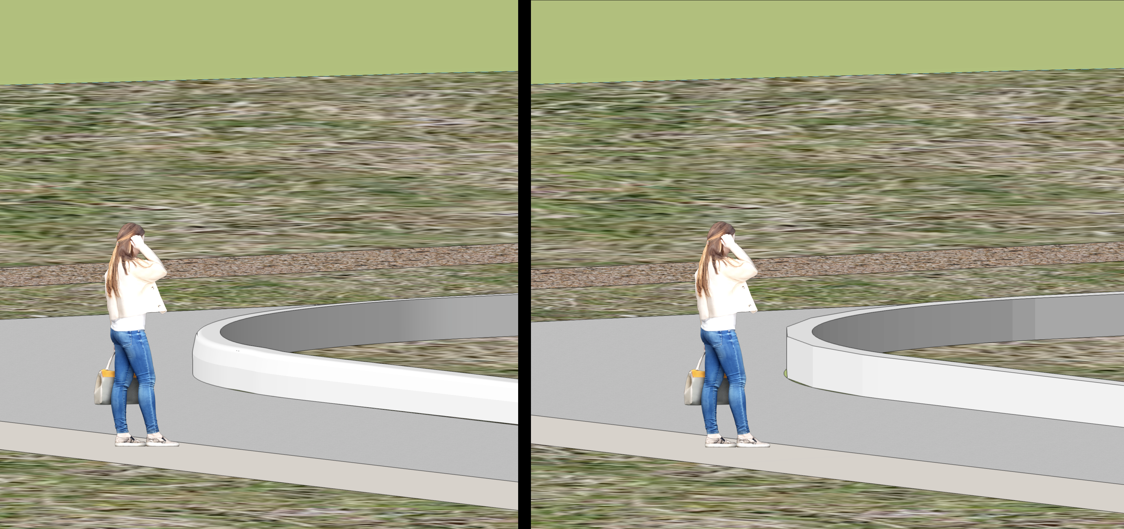
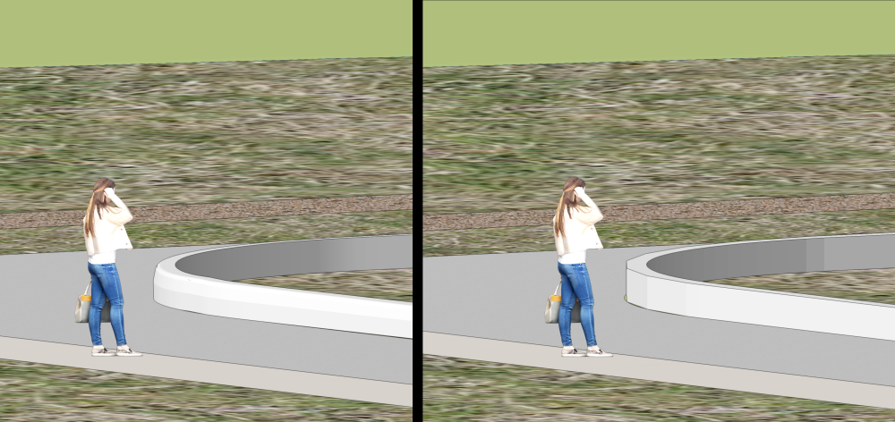
How you approach this comes down to the intended final results.... A BIM like model for documentation or a fairly realistic depiction for Visualization, pick one. Vectorworks isn't suited to do satisfy both conditions particularly well without duplicated effort and breaking the BIM workflow. If you do not need to depict the curb profile in your model, you could use your hardscape's border function to get a rectangular representation and then refer to details for construction documentation. This could get you close enough for most visualization purposes too as the curb will act just like the sidewalk's configuration in 3D. If you need the exact modeling of the curb for visualization purposes, then you need to Extrude Along a Path or similar modeling. The reason your curb didn't extrude is probably due to the method the curve was drawn. If you converted your hardscape to a polyline, there will be a bunch of segments and vertices depicting the curve, but it's hard to say until you explain what you did. If you trace the mesh representation of the hardscape hardscape with a NURBS curve in 3D, you will have a nice path to use for an EAP, but this will take some effort to draw and won't update if you change your hardscapes. NURBS to EAP compared against the Boarder option of your Hardscape. I wonder if the new and improved Fence tool, something I have not tried yet, could be of assistance. Curbs, fences, and site walls always require so many work arounds after all these years one would think the idea of Landscape BIM that's been pushed for so long is pretty much dead... Hope it helps...
-
Nomad- make it useable for on-site work
Jeff Prince replied to Zsombor's question in Wishlist - Feature and Content Requests
I'm a landscape architect too. The community has been asking for a mobile vectorworks for a while, but it sure seems like it's not happening anytime soon. Have you considered using other solution providers instead of Vectorworks for a mobile tablet based workflow? -
How do I change sheet layers from landscape to portrait
Jeff Prince replied to Hanna N's question in Troubleshooting
From the navigation pallet... Select the sheets you wish to change, you can pick multiple. Right click on one of the highlighted sheets Select "page setup" In the next dialog that appears, select "print setup" Change to portrait or landscape and all selected sheets will be updated. You can do similar from Tools -> Organization menu, just remember to hit OK when finished if you do it that way.- 1 reply
-
- 1
-
-
That exists already in most drone photo processing softwares and pretty much every professional LiDAR processing package. You place targets at known locations and the software adjusts accordingly. Trick is, you need those reference targets placed precisely, otherwise you are back to square 1.
-
Rotate it. or Place it on a Sheet Layer instead.
- 1 reply
-
- 2
-
-
for a 2D workflow Create a continuous outline for each patio using the Polyline tool (or polygon with paint bucket). Select the two outlines and look at the OIP. The area will be displayed. Select one and its area will be show, Select both and the combined area will be displayed. for a BIM workflow Use the hardscape tool to develop the patio Use a data tag to report the area with a note and/or create a report to qualify the patios automatically
-
You can edit the meshes in Blender and export them back to Vectorworks with the texture preserved. You’ll want to do that via .obj most likely unless you are pretty familiar with the various ways to shuttle things with Blender.
-
What a peculiar and completely incorrect thing to say. Blender being free isn’t its #1 selling point, it’s just a footnote compared to the amazing capabilities found within it. You are claiming the purchase of two expensive softwares with fewer features is better than the free alternative. The free alternative having an army of 100’s of thousands of users and plentiful freelancers available for hire, the VWX/C4D solution? The free alternative able to generate geometry that Vectorworks chokes on, anyone remember the Mobius strip? The free alternative with a robust offering of add on elements for just about any workflow imaginable vs Vectorworks? You keep digging this hole deeper and deeper, yet fail to answer the question the OP has asked. Then, you use this thread for promoting your YouTube channel or a dumping ground for your unrelated videos celebrating a war? It’s a very sad state of affairs here on the forum. Here's an interesting example of what Blender can do which shreds the VWX/C4D example shared previously, and there's a nice story and behind the scenes to see for your 4 minute investment....
-
This demonstrates your fundamental lack of experience and understanding of Blender. That video could be not only modeled, but also video edited, and sound engineered completely within Blender. But you didn’t know that because you don’t know Blender. Maybe you should stick with what you know… replicating things other people designed using antiquated methods.
-
Prepare and Export Site Model for Laser Cutting
Jeff Prince replied to ThreeDot's topic in 3D Printing
@ThreeDot Be sure to make a backup copy before proceeding. The easiest way is to: 1. Configure your site model settings with desired 2D and 3D contour appearance. 2D Display \ Style: 2D Contours (turn off labels, but leave the border on...it makes a nice frame for your pieces to be cut to and is based off the model crop) Keep in mind, smoothed 2D contours can sometimes have too many verticies and trip up some laser cutters and contour labels will break your contours. 3D Display \ Style: 3D Contours For your model, I would do 3D contours because you can use their Z value as selection criterial for organizing your printing using classes and design layers. 2. Make a copy of your site model and put it on a separate design layer. This will keep things organized and aligned for any common items you want to develop for the cutting process, like alignment keys. 3. Switch to Top view (not Top/Plan) for 3D poly based contours and ungroup. 5. Check your contours and make sure everything looks good. Convert your skirt to a 2D polyline to use as an edge boundary for your model. Now you have the contours you need for cutting out with the laser. You will need to organize them into logical groups for printing to get desired result, which will depend on the shape of the model and the material you intend on using. If you intend on doing a lot of this kind of thing, a script for organizing contours into classes and sheet layers would speed things up. Feel free to ask more questions if needed.- 1 reply
-
- 1
-
-
Obligatory Rhino / SubD comment.
-
This is just incorrect and bad advice.
-
the future is using Data Tags, and the the future is now 😉 Seriously, built-in object tags like the ones in plant objects are a dead workflow.
-
Duplicated contour line labels are a problem
Jeff Prince replied to Jeff Prince's topic in Site Design
Unfortunately, that trick doesn’t work. The second you hit the update button to refresh a texture or graphic mode of the site model, the duplicates will come back even though the site model data has not changed. This problem has been going on so long and Vectorworks doesn’t seem to be fixing it…. The only reliable way to label contours seems to be doing it manually with annotations in the viewport(s) unfortunately. -
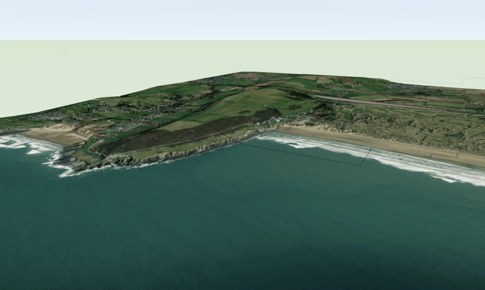
I just read your message. Unfortunately, there was no lidar, .vwx file, or project coordinates attached or in the link provided, so I'm unable to review the site. I did look at the lidar available in what I suspect is your vicinity of interests. It looks like the 2019 data is most comprehensive. I was able to pull that down and generate a site model of a fairly large area using 4 different point clouds. This is good because it tells you the data is there and it's possible to do something with it. Here's some of the vicinity brought into Vectorworks. So, 1st you import the point cloud. It seems the data either lacks geographic location or Vectorworks is not importing it correctly. This is where those .shp files of the LiDAR study area are handy, as those do come into their real world position correctly, so import those first. Then, you can move the point cloud(s) in Top/Plan view to line up with the geometry of .shp files and/or the GIS aerial image built into Vectorworks. Using top/plan for this move prevents you from snapping to an incorrect elevation and preserving the elevation in the LiDAR. Once you have the LiDAR situated correctly, you can convert it to a site model by selecting it and then issuing the "create site model from data" tool. You can choose the number of points to import, which is essentially decimates the point cloud for you and takes out a large number of those trees sticking up in the air. Finally, edit this site model by "recreate from source data". This will give you access to the points. Using the clip cube to work small sections at a time, you can delete points that you do not wish to use. After you are done, the site model will be rebuilt. Repeat the process as required and your model will take on a smoother appearance. In terms of using Blender with geographic point clouds, there is a lot of information on the blender sites and YouTube about Blender GIS and LiDAR Decimation if you want to learn more. Just be warned, this requires installing add-ons and a higher comfort level with Blender. Hopefully @Katarina Ollikainen or @Tom W. can help you out, I'm going on break for a bit 🙂
-
Turn your joint in a symbol. This will give you greater control over graphics and orientation. Plus, when things go wrong, you only have one thing to fix instead 100s 🙂 I draw two crossing lines at 90 degrees. I then color one red and the other green (like the axis) and turn it into a symbol. This gives you visual orientation of the rotation and makes it easier to adjust. See attached file for example. The original joint I created did not rotate correctly so I drew some helper lines and dimensions to determine how the symbol geometry needed needed to be rotated. I left that stuff in there so you can see how it was prior to repair. Using the Red, Green, Blue convention for axis depiction can really help you see what is going on with the tools as you use them and provide insights into how to fix things. Now, you might be wondering "why does Vectorworks place my line in a seemingly random way". It looks that way, but isn't random. Everything is related to the start point of the path. If you draw your joint at the start point of the polyline and in the proper orientation, things will work as they should. It's just we generally don't think like that when designing. So, in your example, the "correct" drawing of the joint would look like the line in green below. It is drawn from the start point of your path to the perpendicular offset path, kind of like your line drawn in red, but orientated about the start point of the path. The cumulative worldwide wasted energy on topics like this due to Vectorworks logic could power a small village in perpetuity 🙂. You would think that selecting the 'center, tangent, keep orientation' options (which you need to activate in this example) would help VWX figure this out, but no, you still have to draw the geometry correctly. DUPE ALONG PATH-symbol trick.vwx

-
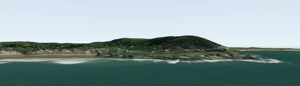
I received your message, but the data was not point cloud data, it was GIS data depicting the area your are interested in, boundaries and descriptors for aerial surveying done to collect lidar, and a geoTIFF DEM. DEMs are raster heightfield information where the greyscale value of a pixel in the image determines elevation. Vectorworks does not have a method of using that type of data. Blender and Rhino do, but you would be better served collecting the actual point cloud files, typical .las, .laz, or .pts. These point cloud files describe geolocated points in 3D space, which Vectorworks does understand. Here's an example of what you can do with raster data in appropriate software: Landscape Visualizations